Ottobock | 5
5.2 Lagerung
Die Angaben im Kapitel „Technische Daten“ beachten.
6 Herstellung der Gebrauchsfähigkeit
6.1 Einbau in den Unterarm/Oberarm
Der AxonMaster 13E500 kann im Unterarmschaft oder bei Versorgung mit den Ellbogengelenken
z.B.: AxonArm Hybrid 12K500, AxonArm Ergo 12K501, im Oberarmschaft positioniert werden.
Die gewölbte Bauform ermöglicht die Fixierung je nach Platzverhältnis im Außenschaft oder zwi
schen dem Außen- und Innenschaft. Ist zwischen Außen- und Innenschaft genügend Platz vor
handen, kann der AxonMaster 13E500 mittels Klettverschlussband befestigt werden. Bei gerin
gen Platzverhältnissen wird der Laminierdummy des AxonMaster 13E500 im Außenschaft einlami
niert.
6.2 Elektrische Versorgung
Die elektrische Versorgung des AxonMaster und der Prothesenkomponenten erfolgt durch den
AxonEnergy Integral 757B500/757B501.
7 Handhabung
7.1 Verbindungsaufbau
Einstellungen an den Prothesenkomponenten können mittels Bluetooth Datentransfer und der
Software AxonSoft 560X500 durchgeführt werden. Dazu muss eine Funkverbindung zwischen
dem AxonMaster 13E500 und dem PC mit Hilfe des BionicLink PC 60X5 aufgebaut werden.
7.2 Auswählen eines Programms
Zur optimalen Anpassung an den Patienten stehen verschiedene Standardprogramme sowie zu
sätzlich die Möglichkeit einer verfeinerten patientenspezifischen Einstellung zur Verfügung. Diese
Standardprogramme können mit der Einstellsoftware AxonSoft 560X500 ausgewählt werden und
beinhalten vordefinierte Steuerungsvarianten und Umschaltmethoden.
An den AxonMaster 13E500 können 2 MyoBock-Elektroden 13E200/202=* und / oder ein Zug
schalter angeschlossen werden. Die Elektrode zum Schließen der Hand wird an Eingang 1 ange
schlossen, jene zum Öffnen der Hand an Eingang 2. Der Zugschalter für z.B. eine Seilzugbanda
ge an Eingang 3. Die restlichen Eingänge können derzeit nicht verwendet werden und bleiben mit
Abdeckkappen verschlossen.
7.3 Rückmeldungen/Betriebszustände
Das intelligente Akkumanagement des AxonMaster 13E500 informiert über den abnehmenden La
dezustand des Akkus, indem die Hand immer langsamer wird bzw. weniger Griffkraft aufbaut.
Das System wird schließlich bei sehr geringem Ladezustand abgeschaltet. Der Akku wird so vor
schädlicher Tiefentladung geschützt.
8 Steuerungsvarianten
8.1 2-Multi
Proportionale Steuerung mit 2 Elektroden.
Die neutrale Position der Michelangelo Hand ist die Ausgangsstellung für Opposition Mode und
Lateral Mode.
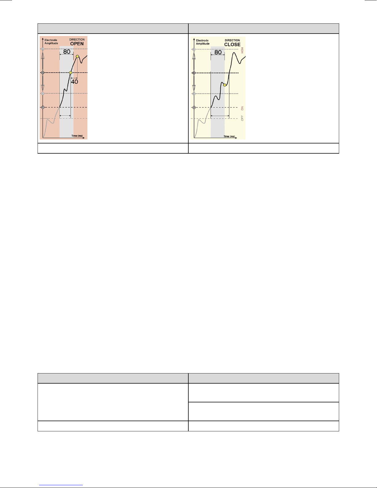
Die Höhe der Griffgeschwindigkeit bzw. der Griffkraft wird von der Höhe des Elektrodensignals
(resultierend aus der Muskelkontraktion) bestimmt. Über ein stärkeres Elektrodensignal kann im
Bedarfsfall jederzeit bis zur maximalen Griffkraft nachgegriffen werden.
Aus einer geöffneten Handstellung wechselt die Michelangelo Hand automatisch in die neutrale
Position, wenn die Hand nicht über die Elektrodensignale gesteuert wird. Während dem Schlie
ßen in die neutrale Position wird die minimale Griffkraft (ca.15 N) aufgebaut.