Healthmark MM513-100 User manual

Instructions for Use: Insulation Tester and Bi-Polar Fixture
Brand Name of Product
Insulation Tester and Bi-Polar Fixture
Generic Name of Product
Insulation Tester and Bi-Polar Fixture
Product Code Number(s)
MM513-100, MM513-600, MM513-120EU, MMBPT-190, MMBUR-0007, MMBRU-
007, MMLSE-0029, MMTRI-0022A, MMSBT-170
Intended Use
This is a compact, handheld, battery operated unit that tests the integrity, such as
pinholes, cracks or defects, of the insulation of electrosurgical instruments in order to
prevent inadvertent tissue burns of laparoscopic and bi-polar electrosurgical instruments.
Range of Applications for Product
Used to test the integrity of the insulation of electrosurgical instruments (ESI) and
cable/cords for: laparoscopic, endoscopic, intra-operative instruments, monopolar and bi-
polar surgical items.
Key Specifications of Product
●Insulation Tester- MM513-100
●Bi-Polar Fixture and Black Connector- MMBPT-190
●Training CD
●Quick Operation Guide (manual)
●On and off switch
●Lightweight portable unit
●Weight: 0.672 lbs (305 grams), voltage: 0V to 5kV fully adjustable, resolution:
10V
●Current output: <0.1mA at probe
●Short circuit: test current < 0.1mA max.
●Power supply: 1800 Ma Li-Polymer Battery
●Probes:
• Medical style brass wire 8mm wide brush, trim length of 2mm (note:
probe size/shape may vary depending on user requirement)
• Reusable/interchangeable brush, ring or tri-hole electrode
• Test stand: Saddle Block
●System case
●Ground wire (green wire) with alligator clip
• 6ft. (2 meter) with clamp on one end
●Power supply option: 5V external rechargeable battery with adaptor
●Lithium Polymer battery
●Dimensions: 8.5 x 3.1 x 1.5 inches (215 x 78 x 38mm)
●10-hour operational time (up to 1000 instruments), 2–4-hour recharging cycle
●Simple operation, easy to read LED indicators
●Maintains applied test voltage with constant current source
●Full test current at low voltages
●Limited output current for operational safety
●Voltage up and down buttons
●LED displays alarm (audible and visual) and battery charge
●EU insulation tester
●C Style adapter wall charger
Kit Contents
Insulation Kit Includes:
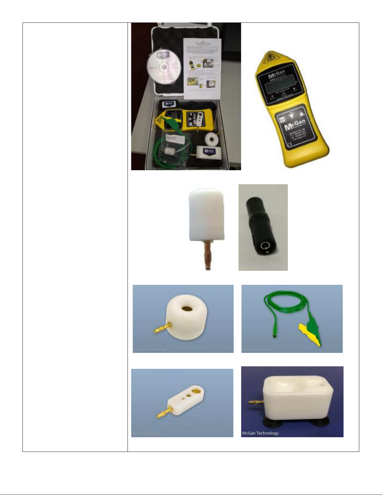
Insulation Kit Insulation Tester MM513-100
(Bi-Polar Fixture Black Connector)-MMBPT-190
Ring and Brush Electrodes-MMLSE-0029 Ground Wire with Alligator Clip
Tri-Hole Electrode- MMTRI-0022A Saddle Block- MMSBT-170
Brush- MMBRU-007 Case
Quick Start Manual
Shipping & Storage
Shipping Conditions &
Requirements
N/A
Storage Conditions
N/A
Packaging Conditions
N/A
Shelf Life
N/A
Instructions for Using Product
Description of Use(s)
Used to test the integrity of the insulation of electrosurgical instruments.
Preparation for Use
1. Turn the unit on.
2. Check battery LED indicator colors:
Red=Battery Flat Blue=Charging Green=Battery Full

a. If the battery level is blue or red, recharge unit using the adapter supplied
with the insulation tester kit.
b. Use of any other charger may cause damage to the insulation tester unit and
void warranty.
c. Only use this unit if it is at Green=Battery Full
1. Connect the HV probe and ground leads to the unit.
2. Connect the ground clamp to the metallic substrate of the item to be tested,
substrate should be grounded.
3. Attach the selected McGan probe (ring, brush, Tri-Hole or Saddle block) to the
HV Wire or base unit port (red).
4. Turn the unit on and select voltage.
5. Place the probe near the metal substrate.
6. A spark should occur (if not re-check all leads).
7. The unit should now be ready for use.
8. Test the coated surface by lightly moving the probe (brush, ring, Tri-Hole
electrode) slowly (approximately 3 feet every 4 seconds) across the surface of
the unit under test. See Operational Guide for saddle block.
Diagrams (drawings, pictures)
N/A
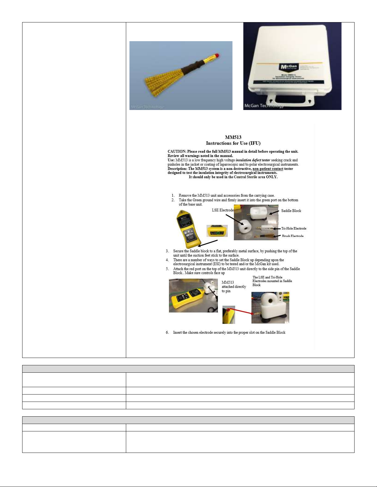
Steps for Use of Product
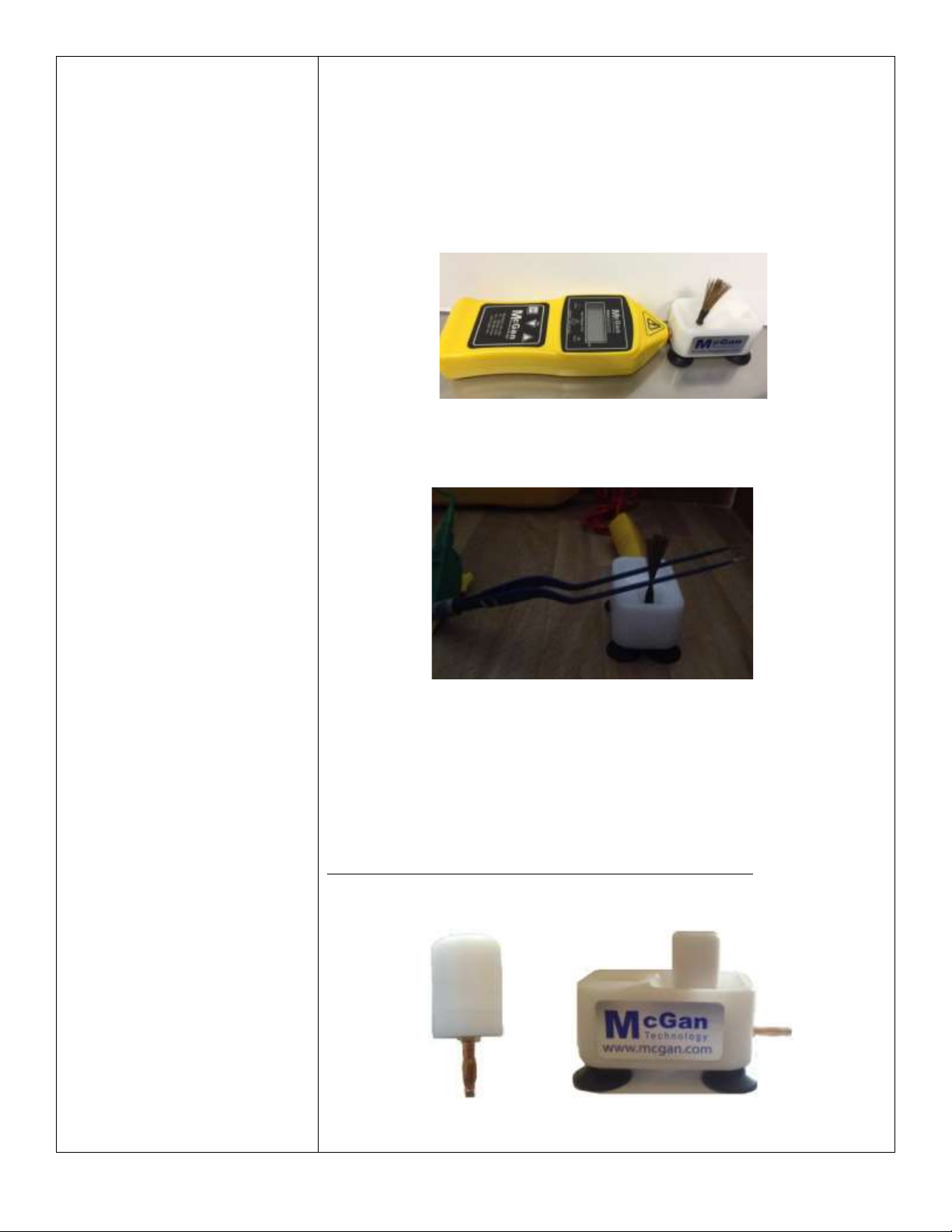
1. Remove the insulation tester unit and accessories from the carrying case.
2. Take the green ground wire and firmly insert it into the green port on the bottom
of the base unit. Fig. 1
Figure 1 Insulation Tester
Figure 1 Accessories
3. Secure the saddle block to a flat, preferably metal surface, by pushing the top of the
unit until the suction feet stick to the surface. Fig. 2
Figure 2
4. Attach the red port on the top of the insulation tester unit directly to the side pin of the
saddle block. Make sure controls face up. Fig. 3
Figure 3 Figure 3
Note: There are several ways to set the saddle block up depending upon the
electrosurgical instrument (ESI) to be tested and/or the kit used.
1. Insert the chosen electrode securely into the proper slot on the saddle block.
2. Take the clamp on the green ground wire and attach it to the conductive core of
the instrument under test.
3. Turn the base unit on and set the voltage to 2.8KV ± 0.3KV. Fig. 4
4. Use 4.2 ± 0.3 kV when using the Tri-Hole electrode.
Figure 4
5. Push the ESI under test through the LSE ring electrode slowly (approximately 3
feet every 4 seconds).
6. The alarm will sound when the ESI is first inserted into the electrode as that is
the bare tip of the instrument.
7. After the test is completed, turn the base unit off and remove the clamp end
from the unit under test, remove the electrode from the probe wire and remove
the ground wire and probe wire from the base unit. Properly store the unit and
accessories away.
8. Follow the properly established hospital procedure after testing is completed
with regards to the instrument under test.
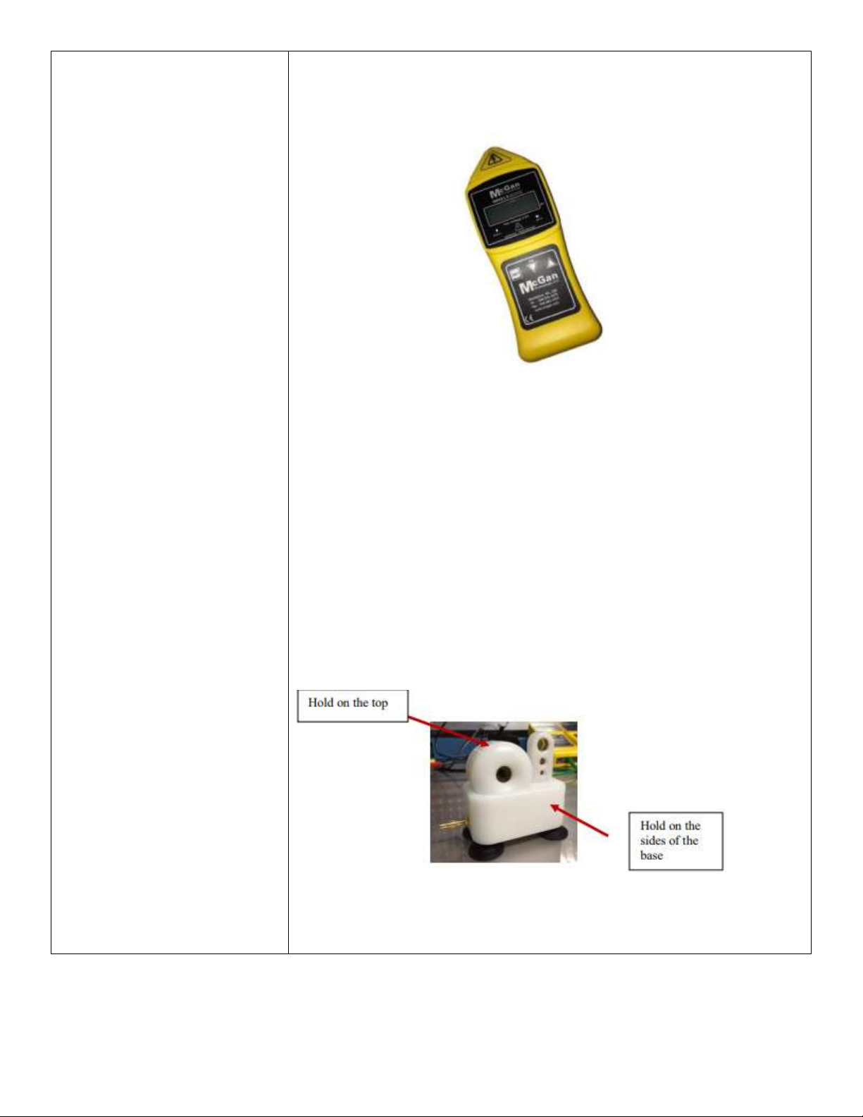
Note: The unit should always be switched off prior to removing or repositioning of the
ground lead, the HV red wire or the saddle block. If the unit is on and you touch the
ground lead (clamp end) and the probe end of the base unit at the same time you will
receive a very mild “tingle”. To remove the possibility of receiving the “tingle”, always
use surgical gloves when handling the leads. You can hold the saddle block from the top
or the sides as long as you do not touch the connection points. Fig. 5
Figure 5
For Round ESI such as laparoscopic:
1. Insert the chosen electrode into the proper slot in the top of the Saddle Block.
Make sure the pin is securely placed in the hole. Fig.6
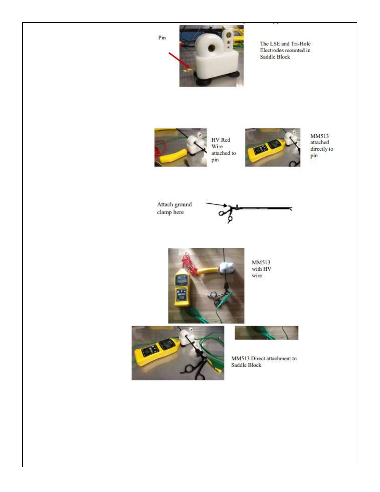
Figure 6
2. If using the MM513 Kit attach the HV Red wire to the pin on the side of the
Saddle Block OR connect red port o the top of the unit directly to the side pin.
Make sure controls face up. Fig. 7
Figure 7
3. Take the clamp on the Green ground wire and attach it to the conductive core of
the instrument under test. Fig. 8
Figure 8
4. Turn the base unit on and set the voltage to 2.8kV +/- 0.3kV. Fig. 9
Figure 9
5. Push the ESI under test through the LSE ring electrode slowly (approximately 3
feet every 4 seconds).
6. The alarm will sound when the ESI is first inserted into the electrode as that is
the bare tip of the instrument.
7. Alarm will sound and LED will flash if a fault is found in the coating which will
indicate a fault with the instrument.
Using the Tri-Hole Electrode:
1. The setup is the same as shown above except turn the voltage to 4.2KV+/-
0.3KV.
2. Insert the round electrosurgical instrument ESI into hole size closest to the
diameter of the ESI under test. Note: Hold sizes are slightly larger than 3mm,
5mm, and 10mm from the bottom (pin side) up.
Bi-Polar instruments (wear gloves):
1. Attach the red port on the top of the insulation tester unit directly to the side pin
of the saddle block. Make sure controls face up.
2. Place the brush electrode into the saddle block in the slot on the right side away
from the pin. Fig. 10
Figure 10
3. Attach the green ground wire to the back end of the bi-polar forceps. Make sure
the clamp is connected to both pins.
4. Insert the end of one time of the bi-polar forceps into the middle of the brush.
Fig. 11
Figure 11
5. Turn the base unit on and set the voltage to 3.0 to 3.5kV.
6. Slowly push the bi-polar forceps away from you. Go from the tip of the forceps
to the base.
7. Repeat using the second time.
8. Turn the bi-polar forceps over and repeat the test of both tines.
9. Alarm will sound and LED will flash if a fault is found in the coating which will
indicate a fault with the instrument.
Instructions for Using Bi-Polar Kit with the Insulation Tester Saddle
Note: Wear gloves.
1. Insert the bi-polar fixture in the saddle in the slot for the LSE ring electrode.
Fig. 12
Figure 12
2. Remove the clamp from the end of the green ground wire.

3. Insert either end of the black connector adaptor onto the end of the green wire.
Fig. 13
Figure 13
4. Insert the bi-polar fixture into the end of the black adapter.
5. Insert the bi-polar instrument into the top of the bi-polar fixture. Fig. 14
Figure 14
6. Turn on the insulation tester unit on and set voltage to 2.8v +/-0.3v.
7. Touch the bare tip of the bi-polar forceps to ensure that the alarm sounds, and
the system is operational.
8. Using the brush, slowly brush from top to bottom of each: Fig. 15
a. On the outside of left side of tine
b. On the inside of left side of tine
c. On the inside of the right tine
d. On the outside of the right tine
Figure 15
9. If the alarm sounds, the bi-polar has a fault. Follow standard facility procedures
for a defective electrosurgical instrument (place a repair tag on all instruments
that fail testing).
Interpretation of Test Results
N/A
Contraindications of Test Results
N/A
Documentation
N/A
Special Warnings and Cautions
●This should be used in the Sterile Processing area ONLY during assembly and
inspection.
●The Lithium Polymer Battery can only be replaced at the McGan facility. DO
NOT attempt to replace the battery.

●Use the charger that comes with the units.
●DO NOT simultaneously handle the brush electrode and ground clamp as it will
cause a mild “tingle”. Use surgical gloves as a precaution against receiving the
“tingle”.
●You cannot operate the MM513 unit with the AC Adaptor plugged into the
rechargeable battery port on the bottom of the base unit.
●Led battery indicator light will illuminate when the unit is low on power. If the
power from the battery is too low, then the LED will not have enough power
and will not illuminate. IF the MM513 fails to operate due to battery failure,
contact Customer Service.
Troubleshooting
Symptom
Possible Cause
Solution
No display
Dead or low charged
battery
Fully charge battery
pack
Alarm sounds
continuously during test
Surface might be
slightly conductive,
damp or salty.
Probe moved too fast
Wash, clean and dry the
surface.
Move probe
approximately 3 ft (1m)
every 4 seconds
No alarm on defect
Voltage too low
Increase voltage
sensitivity
No spark at probe tip
Damaged leads
Poor connections
Dead or low charged
battery
Repair or replace leads
Clean and reconnect
Recharge the battery
No battery indicator
light and unit does not
function
Dead or low charged
battery
Recharge the battery
Disposal
N/A
Reprocessing Instructions
Point of Use
Inspect: For the alarm to sound and LED to light and the base unit is in clean and proper
working condition.
Preparation for Decontamination
N/A
Disassembly Instructions
N/A
Cleaning –Manual
Base Unit
●Dab a lint free cloth in alcohol and wipe down base unit.
Caution: DO NOT get alcohol in/near the battery terminals, the green or red ports.
DO NOT saturate cloth.
Red HV Wire/Green Ground Wire
●Inspect: Make sure that there are no cuts, brakes or abrasions on the cable
insulation. If they are replaced, make sure connector post is not damaged.
●Use an alcohol swab and wipe both the red and green wires, including the mini
handle (yellow) on the red HV wire.
Caution: DO NOT get alcohol in/near red port on the top of the mini handle.
DO NOT use a saturated cloth.
Reusable Brush Electrode
●Inspect: Make sure all bristles are not damaged.
●Can be wiped with alcohol.

Reusable Saddleblock
●Inspect: Inspect for cracks in white housing. If they are replaced. Make sure
electrode components fit securely in the proper slot.
●Can be wiped with alcohol.
Thoroughly DRY all areas before using the components. Inspect for any defects in
the electrodes.
Cleaning –Automated
N/A
Disinfection
N/A
Drying
N/A
Maintenance, Inspection, and
Testing
●Some organic materials may attack plastic parts and cause early degradation.
Contact with such materials should be avoided.
●It is recommended that the base unit of the MM513 base unit (P/N MM513-110)
be calibrated at least once per year to ensure that the unit is operating at the
appropriate voltage. McGan Technology can perform this service for a small
fee. Please contact McGan if you would like pricing or need to set up a test
system. Recalibration is recommended when the instrument’s integrity is in
question or the instrument has been damaged.
Reassembly Instructions
N/A
Packaging
N/A
Sterilization
N/A
Storage
N/A
Additional Information
Subject to the warranty conditions below MM513 is warranted by the manufacturer to be
free from defects arising from defect design, or workmanship for a period of 12 months
from the date of original purchase by the user.
Probes and leads are warranted for 2 months. They are consumable items, and subject to
wear and deterioration during use. The life of these parts can be extended by keeping
them in a clean and dry condition. The probes and leads must be stored in suitable
protective containers. During use, avoid “scrubbing” the probe along the surface of the
workpiece.
The warranty will be voided if the base unit (P/N MM513-110) has been disassembled
for any purpose. It is not necessary to access any component inside the unit. Return the
unit for repair.
Related Healthmark Products
N/A
Other Product Support Documents
ProSys™ Brochure, ProSys™ Price List
Reference Documents
N/A
Customer Service Contact
Healthmark Industries Company, Inc.
18600 Malyn Blvd.
Fraser, MI 48026
1-586-774-7600
healthmark@hmark.com
hmark.com
2021-11-03 Suzanne Latta
Other manuals for MM513-100
1
This manual suits for next models
8
Table of contents
Other Healthmark Test Equipment manuals


