PCWork PCW05A User manual

User Manual PCW05A
Digital Clamp Meter

2
English .............................................................................. 3
Deutsch .......................................................................... 34
Français .......................................................................... 65
Português ....................................................................... 96
Italiano .......................................................................... 127
Please check www.pcworktools.com for the latest manual and the digital
version.

3
Copyright Statement ............................................................... 4
Safety Statement .................................................................... 4
General Notes ........................................................................ 5
Safety Instructions .................................................................. 6
Safety Symbols ....................................................................... 9
Product Description .............................................................. 10
Measurement Operation ....................................................... 13
AC/DC Current Measurement .............................................. 14
AC/DC Voltage Measurement .............................................. 15
Frequency / Duty Measurement ........................................... 17
Resistance Measurement ..................................................... 18
Continuity Test ...................................................................... 19
Diode Test ............................................................................. 20
Capacitance Measurement ................................................... 21
NCV Test .............................................................................. 22
Temperature Measurement .................................................. 23
General Technical Specifications .......................................... 25
Maintenance ......................................................................... 31
Information regarding waste disposal ................................... 32
EN User
Manual

4
Copyright Statement
In accordance with international copyright law, you are not allowed to copy the
contents of this manual in any form (including translations) without given permission in
written form by the distributor.
Safety Statement
The “Caution” symbol refers to any condition or operation which might cause
damage to the instrument or equipment.
Any such operation has to be performed with caution. If incorrectly performed or
without following the procedures, the instrument and equipment might get damaged. In
case that conditions are not fully met or not fully understood, do not continue to
perform any operation flagged with the “Caution” symbol.
The “Warning” symbol refers to any condition or operation which might cause
damage to the user. Any such operation has to be performed with caution. If incorrectly
performed or without following the procedures, personal injury or casualties might
result. In case these conditions are not fully met or not fully understood, do not
continue to perform any operation flagged with the “Warning” symbol.

5
General Notes
• It is not permitted to change the manual in any way or add additional content,
without given permission in written form by the distributor.
• The operator of this device is obliged to ensure that every other person using this
device has read and understood the manual, especially the safety instructions.
• The operator is obliged to ensure proper usage, a functioning device prior usage,
the provision of the manual, and that only qualified users operate the device.
• Any change related to the design or construction of the device is not permitted.
• Warranty and any liability in regards to material damage or personal injury are
suspended in the following cases:
§ Improper usage and operation of the device
§ Not following the instructions and safety regulations provided by the manual
§ Operation and usage without wearing proper personal protection equipment
§ Usage and installation of non-approved spare parts
§ Improper maintenance and changes related to the design or construction of the
device; removal of the type plate

6
Safety Instructions
The instrument is designed according to the requirements of the international electrical
safety standard IEC61010-1, which defines the safety requirements for electronic
testing instruments. The design and manufacturing of this instrument strictly comply
with the requirements of the IEC61010-1 CAT.III 600V,over voltage safety standard
and pollution level 2.
Warning:
In order to avoid possible electric shock, personal injury, or any other safety
accident, please abide by the following instructions:
• Please read this manual carefully before using the instrument, and pay special
attention to safety warning information.
• Strictly follow this manual when using the instrument. In addition, pay attention to
any safety information on the device itself. Otherwise, the protection function of the
instrument may be damaged or weakened. Safe operation and safety for the user
cannot be guaranteed in this case.
• Do not measure current with the test leads still inserted into the device’s sockets.
• Avoid working alone, thus assistance can be provided, especially in emergency
situations.

7
• Do not provide children access to the multimeter. Parents are fully responsible for
any safety hazards caused by non-compliance.
• Please be careful if the measurement exceeds 30V AC True RMS, a 42V AC peak,
or 60V DC. There might be the danger of getting an electric shock with this kind of
voltage. Follow all relevant safety requirements.
• When measuring known voltage, in order to check if the device works normally,
results in the device not working normally or being damaged, stop any measuring
operation and do not continue using the multimeter.
• Before using the device, please check whether it has any crack or plastic damage.
If so, do not use the device.
• Before using the instrument, please check whether the probes are cracked or
damaged. If so, please replace them with the same type, having the same electrical
specifications.
• The instrument shall be used in accordance with the specified measurement
category, voltage, or current rating.
• Do not exceed the max. input values as specified in this manual or on the device.
• Never change the measurement function during a measuring operation on an object
or circuit. Always disconnect the measuring object/circuit first.
• Opening, repairing, or maintenance should only be executed by trained/qualified
professionals.

8
• Never look directly into the LED flashlight of the device. Non-compliance bears the
risk of permanently damaging your eyesight.
• Please comply with the local and national safety code. Wear personal protection
equipment to prevent any injury through being exposed to electrical shock or
electrical arc caused by an exposed hazardous live conductor.
• When low battery is indicated, please replace the battery in time to prevent of any
measurement error.
• Do not use the instrument around explosive gas, steam, or in an wet environment.
• When using the probe, please put your fingers behind the finger protector of the
probe.
• When measuring, please connect the zero (neutral) line/ ground line first, then
connect the live wire; when measuring is done, please disconnect the live wire first,
then disconnect the zero (neutral) line / ground line.
• Before opening the outer cabinet or the battery cover, please remove the probes
from the device. Do not use the device, when it is taken apart or the battery cover
is open.
• The safety standards are only met when the instrument is used together with the
supplied probes. If the probes are damaged and need to be replaced, only use
probes with the same model number and the same electrical specifications for
replacement.

9
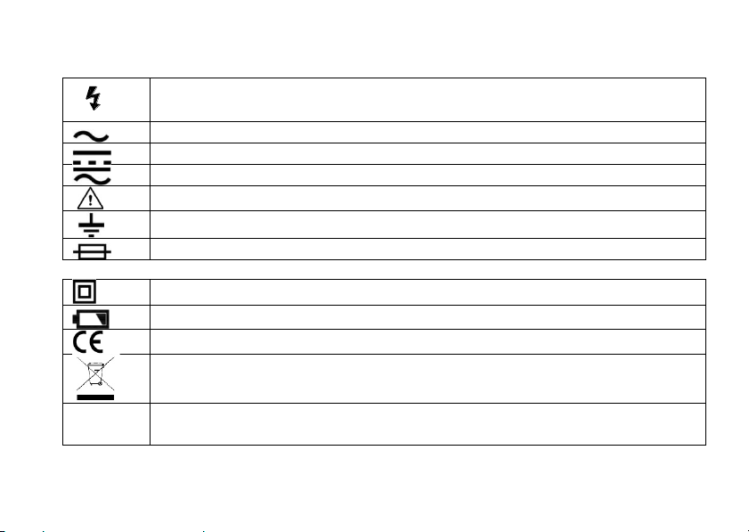
High voltage warning (dangerous voltage might be present)
AC (Alternating current)
DC (Direct current)
AC or DC
Warning, important safety information
Ground
Fuse
Equipment with double insulation/reinforced insulation protection
Low Battery
Product complies with all relevant European directives
Do not dispose of this electrical/electronic product as unsorted household
garbage.
CAT. II
Suitable for testing and measuring circuits directly connected to power
points (sockets and similar) of low voltage power installations.
Safety Symbols

10
CAT. III
Suitable for testing and measuring circuits connected to the distribution part
of low voltage power supply devices in buildings.
Product Description
Instrument Panel Description
① NCV probe
② Current Sensing Clamp
③ Flashlight
④ Data Hold / NCV Button
⑤ Rotary Function Switch
⑥ Current Clamp Opening Trigger
⑦ Function Buttons
⑧ LED Display
⑨ Current Input Socket (red test
lead)
⑩ COM Input Socket (black test
lead)

11
Function Buttons
Zero Correction for DC Measurement
Through this function, the user can set the magnetization effects to zero when
measuring DC current. It should be done after each high current measurement.
Before conducting the measurement (no conductor inserted in clamp), press and
hold the button for ca. 3 seconds until you hear an acoustic signal (beep) and the
ZERO symbol is shown on the screen.
Function Selector (secondary functions)
Press the button to switch between the respective secondary functions of the
measurement mode (e.g. switch between AC or DC when measuring current)
Press the button to enter the MAX/MIN mode. Here the device will temporally save
the highest/lowest values it records. Press and hold the button again (for more than
2 seconds) to exit the MAX/MIN mode.
Backlight: Press the button to turn on the display’s backlight. Press it again to turn
off the backlight. After 10 seconds the backlight will automatically turn off.
Flashlight: Press the button for more than 2 seconds to turn on/off the flashlight.
HOLD Function: Press the button to record data. Press it again to exit the hold
function.
NCV function (non-contact AC voltage detection): Press and hold the button for
more than 2 seconds to activate or deactivate the NCV function

12
Low Pass Filter (LPF) Function for AC Measurement
The LPF function enables the device to filter interfering signals of over 60 Hz, which can
lead to inaccurate measurement results.
Measurement with the LPF function: Set the rotary switch to either the 600A, 60A, or V
measurement mode. Then press the “Z/F” button 3 times until appears on the
display. Note: the LPF function is only available in AC measurement modes.
Low Impedance Voltage Measurement (LowZ) Function
The LowZ function enables you to measure AC voltage with a lower impedance (approx.
300 kW). The device lowers its internal resistance to prevent „phantom“ voltage
readings. Therefore, the circuit is more heavily loaded when the function is enabled.
Set the rotary switch to “LowZ” to use the function. Caution: The measurement with the
the “LowZ” function cannot exceed the specified values (600V). Do not measure with
the function for more than 1 minute continuously, otherwise the device might get
damaged.

13
Auto Power Off
• If there is no operation for 15 minutes , the device will turn off automatically to save
power. After an automatic shutdown, press any button to turn the device on again.
• If you press the "FUNC." button and turn on the device, the automatic shutdown
function will be disabled. After turning off the device, the automatic shutdown
function will be enabled again for the next measuring session.
True RMS
This device measures values in “True RMS”.
High Voltage/Current Indication Function
When the measured voltage is greater than 80V or the measured current is greater than
1A, the orange backlight of the display will light up, prompting users to be careful.
Auto Range Function
When using the device, the correct range for each measurement function is chosen
automatically by the device.
Measurement Operation
Connect Measuring Probes
Do not operate the device before the test probes are not connected correctly. To ensure
this, push the cables fully into the input sockets.

14
AC/DC Current Measurement
Current is measured via the current clamp of the device. You can
do measurements of insulated and non-insulated conductors.
Always disconnect the probes before measuring current.
1. Turn the rotary switch to and select the appropriate range
(60A or 600A). Then select either the AC or the DC current
function with the "Z/F" button.
2. Press the clamp release trigger and open the clamp. Now
grasp the conductor to be measured and close the clamp
through the leaver. Ensure to position the conductor in the
middle between the 2 positioning markings on the pliers.
WARNING: do not surround more than 1 conductor. If the
supply and return conductors (e.g. L & N) are measured, they
will cancel each other out and no result is displayed. Measure
them separately. If they are together in one cable, use a cable
separator to measure the conductors separately.
3. The results will be shown on the display. If the measured
current is >3A, the orange backlight of the display will turn on.
4. During AC current measurement, press the “Z/F” button to
display the frequency value or to switch to the LPF function.
DC current
measurement
example

15
AC/DC Voltage “V / mV" Measurement
1. Turn the rotary switch to the measurement function “ ” and
select either the AC or the DC voltage function with the "Z/F"
button.
2. Insert the red probe in the “INPUT” socket and insert the black
probe in the “COM” socket.
3. Connect the probes’ tips (red probe is the positive pole, black
probe is the negative pole) in parallel to the measuring circuit,
measure the voltage.
4. The measurement result is displayed on the screen. When
measuring AC voltage, press the “Z/F” button to display the
frequency value or to switch to the LPF function.
5. If low impedance measurements are required, turn the rotary
switch to the “LowZ” position and press the “Z/F” button to
switch between AC and DC voltage.
DC voltage
measurement
example

16
WARNING:
• Do not measure voltage above 600V; otherwise the instrument might get
damaged and there is a risk of injury.
• If the display shows “OL”, disconnect the probes’ tips from the measuring
circuit immediately (Overload)
• Pay special attention to safety when measuring high voltage to avoid electric
shock or personal injury.
• Always test known voltage before using the device, in order to ensure that
the device functions properly.
• Do not touch the bare tips of the probes; when measuring is finished, always
remove the probes from the measuring object and the device.
Caution:
High impedance voltage measurement: 10M
Ω
Low impedance voltage measurement: 300k
Ω
Note: When the measured voltage is greater than 80V, the orange backlight of the
display will light up.

17
Frequency / Duty Cycle Measurement
1. Turn the rotary switch to the measurement function “Hz%”.
Press the “Z/F” button to switch between frequency or duty
cycle measurement.
2. Insert the red probe in the “INPUT” socket and insert the black
probe in the “COM” socket.
3. Connect the probes’ tips (red probe is the positive pole, black
probe is the negative pole) in parallel to the measuring circuit,
measure the frequency or duty.
4. The measurement result is displayed on the screen.
WARNING:
• Do not measure voltage above 10V; otherwise the
instrument might get damaged.
• Pay special attention to safety when measuring high
voltage to avoid electric shock or personal injury.
• Always test known voltage before using the device, to
ensure that device functions properly.
• Do not touch the bare tips of the probes; when measuring
is finished, always remove the probes from the measuring
object and the device.
Frequency
measurement
example

18
Resistance Measurement
1. Turn the rotary switch to the measurement function “ ” and
select the resistance measurement function with the "Z/F."
button. The display will show “M”, “OL”, and the “W” symbol.
2. Insert the red probe in the “INPUT” socket and insert the black
probe in the “COM” socket.
3. Connect the probes’ tips (red probe is the positive pole, black
probe is the negative pole) to the measuring object, measure
the resistance.
4. The measurement result is displayed on the screen.
5. If the screen shows “OL”, the measurement range has been
exceeded or the measuring circuit is defective.
WARNING:
• Do not measure voltage above 10V; otherwise the
instrument might get damaged.
• When measuring resistance on the line, disconnect the
power supply, ensure there is no source of voltage, and
discharge all capacitors. Otherwise, the instrument might
get damaged and might be in danger of an electric shock.
When measuring is finished, always remove the probes
from the measuring object and the device.

19
Continuity Test
1. Turn the rotary switch to the measurement function “ ” and
select the continuity test function with the "Z/F." button. The
display will show “ ”, “OL” and the “W” symbol.
2. Insert the red probe in the “INPUT” socket and insert the black
probe in the “COM” socket.
3. Connect the probes’ tips to the measuring object.
4. The buzzer will signal if continuity is present (resistance <30W)
and the orange backlight will turn on. In addition the resistance
will be shown on the screen. If the screen shows “OL”, the
measurement range has been exceeded or the measuring
circuit is defective.
WARNING:
• Do not measure voltage above 10V; otherwise the
instrument might get damaged.
• When testing for continuity on the line, disconnect the
power supply, ensure there is no source of voltage, and
discharge all capacitors. Otherwise, the instrument might
get damaged and might be in danger of an electric shock.
When measuring is finished, always remove the probes
from the measuring object and the device.

20
Diode Test
1. Turn the rotary switch to the measurement function “ ” and
select the diode test function with the "Z/F." button. The display
will show “ ”, “OL” and “V”.
2. Insert the red probe in the “INPUT” socket and insert the black
probe in the “COM” socket.
3. Connect the probes’ tips with the measuring diode. If known,
connect the red probe’s tip with the anode and the black
probe’s tip with the cathode.
4. The measurement result is displayed on the screen.
5. If the screen shows “OL”, the measuring diode is either in
reverse direction or defective.
WARNING:
• Do not measure voltage above 10V; otherwise the
instrument might get damaged.
• When conducting a diode test on the line, disconnect the
power supply, ensure there is no source of voltage, and
discharge all capacitors. Otherwise, the instrument might
get damaged and might be in danger of an electric shock.
When measuring is finished, always remove the probes
from the measuring object and the device.
Table of contents
Languages:
Other PCWork Test Equipment manuals