manuals.online logo
Brands
  1. Home
  2. •
  3. Brands
  4. •
  5. IDEAL
  6. •
  7. Test Equipment
  8. •
  9. IDEAL Vol-Con 61-076 User manual

IDEAL Vol-Con 61-076 User manual

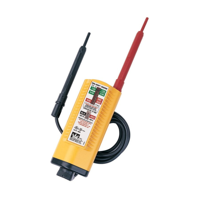
Vol-Con®Voltage/Continuity Tester
Instruction Sheet
#61-076, 61-079, 61-080
Usage Instructions
• Testing for Continuity – no switching required
Place tester across terminals (live or dead) of components or circuit to be tested. The continu-
ity LED (same as “ + DC” LED) will come “On” when resistance between prods is 500K ohms
or less. Full brightness of the continuity LED occurs when the resistance between prods is
300K ohms or less. Reversing prods will verify continuity versus low volt DC.
• Locating Blown Fuses (single phase, three phase and DC)
Turn Power Off. Place tester across the suspected fuse to perform continuity
check. If continuity LEDcomes “On,” the fuse is good. If the continuity LED
does not come “On,” the fuse is defective.
For locating a blown fuse with the power on, place tester across the “source”
side of one fuse and the load side of an adjoining fuse. If no voltage is indi-
cated, the fuse next to the load side prod is blown. If voltage is indicated,
the fuse next to the load side prod is OK. Repeat the same test with the
prods on the opposite side of the same two fuses to check the other fuse.
On a three phase circuit, repeat the same test as above. An indication of no
voltage or lower than normal line voltage indicates the blown fuse.
• Finding Grounded Side of Line (neutral)
Touch one test prod to the ground and the other test prod to each of the line
terminals until one is found that does not give a voltage indication, that one is
the grounded side of line and the continuity LED should be “On.”
• Testing for “Grounded”Side of Motor or Appliance
With power to motor or appliance “Off,” touch one test
prod to the frame and the other prod to each of the terminal
connections. The terminal which turns the continuity LED
“On” is the grounded side. With power to motor or appli-
ance “On,” place tester across the frame and to each of the
terminal connections. The terminal which does not give a
voltage indication, but does give a continuity indication, is
the grounded side.
• Testing for 25 to 60 Cycle Frequency
Place tester between each side of AC line. A low frequen-
cy hum and slow vibrations indicate 25 cycle current. 60
cycle current is indicated by a higher frequency hum and
more rapid vibrations.
•Checking Continuity of Cords,Motors,Appliances,etc.
Remove power source and place tester across circuit to be
tested. Continuity LEDwill come “On” if resistance is less
than 500K ohms.
• Locating Excessive Leakage to Ground
Place tester across the neutral terminal and the ground, only the continuity
light should come “On,” indicating neutral and ground are connected. If the
“ – DC” light also comes “On,” there is a 5VAC or greater between neutral
and ground indicating a high resistance leakage to ground. High resistance
leakage is qualified since a low resistance (high current) leak to ground
would open a circuit breaker or blow a fuse.
ND 2838-1 Vol-Con Test Inst sh 11/29/00 11:12 AM Page 1
99 Washington Street
Melrose, MA 02176
Fax 781-665-0780
TestEquipmentDepot.com
Cautions
• To avoid the risk of electrical shock, discon-
nect test leads before removing the battery
pack. Do not operate unit with the battery
pack removed.
•Do not use on over 600 volts. This instrument
is for intermittent service only. The duty cycle
on:off ratio is 1:7 for 240 volts or less, and
1:40 for 240 volts or greater. Fifteen seconds
is the maximum “On” time.
•All indications are relative. For determining
the nominal line voltage only.
•Do not use unit with battery packs removed.
Unit may be used for “checking for voltage”
without batteries; however, the battery packs
must be in place for safe operation.
•Always remove right angle plug on lead set
prior to removing battery packs.
Note: If LEDon the left does not come “On”
when it should, check the battery pack on the
left. If LED on the right does not come “On”
when it should, check the battery pack on the
right. Pack may not be fully seated, batteries
may not be oriented correctly or batteries are
bad.
Assembly Instructions
•Remove lead set plug. Remove the two bat-
tery packs adjacent to the lead set, plug
opening. Use screwdriver as a lever, insert-
ing tip in slot at edge of cap and under the
battery pack head. A light force will pop the
pack loose for easy hand removal.
• Insert four 1-1/2 volt watch/calculator batter-
ies (two per each pack), putting negative ter-
minal down as indicated on the side of the
battery pack. Use Union Carbide Corp.
Type A76VP, Eveready No. 357 or IDEALNo.
61-201.
•Orient the battery packs and snap into tester.
Be sure the packs are fully seated.
•Press right angle plug on lead set into the
bottom of the tester. (Place plug on a bench
or solid object and push tester into plug.)
This is a tight fit to keep moisture away from
pins and to prevent accidental plug
release. Be sure the plug is fully
seated.
• Retract “safety shield” on prod tips
and lock by rotating. Place one
prod into the “probing position” by
putting the handle into the prod
storage well. Bring the two
exposed tips into contact with each
other; the continuity LED (LED to
the left) should now be “On.” This
assures batteries on the left side
are good and your “lead set” is in
good working condition. Always
perform this test before using
tester.
• Test a known live AC circuit such as
120 volts. Both LEDs should be
“On”; the neon should have “fired”
if voltage is over 80 and the sole-
noid coil indicator should be acti-
vated. Tester is now operational.
Neon Bulb Left LED Right LED Scale
Continuity Off On Off No movement.
OpenCircuit
No Voltage Off Off Off No movement.
6-65 AC Off On On No movement.
6-90 DC Off On if black prod is On if red prod is No movement.
on negative, off if on negative, off if
it is on positive. prod is reversed.
65-110 AC On On On Little or no
movement.
90-110 DC On On if black prod is On if red prod is Little or no
on negative, off if on negative off if movement.
it is on positive. prod is reversed.
110-600AC On On On
Scale indicates
relative
magnitude.
110-600 DC On On if black prod is On if red prod is
Scale indicates
on negative, off if on negative, off if
relative voltage.
it is on positive. prod is reversed.
Warranty limited solely to repair or replacement; no warranty of merchantability, fitness for a particular purpose or consequential
damages.
ND 2838-1 Vol-Con Test Inst sh 11/29/00 11:12 AM Page 2
Other manuals for Vol-Con 61-076

2

This manual suits for next models

2

Other IDEAL Test Equipment manuals

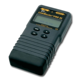
IDEAL LinkMaster PRO XL User manual

IDEAL

IDEAL LinkMaster PRO XL User manual

IDEAL VoltAware 61-025 User manual

IDEAL

IDEAL VoltAware 61-025 User manual

IDEAL Super Series 4 User manual

IDEAL

IDEAL Super Series 4 User manual

IDEAL 61-520 User manual

IDEAL

IDEAL 61-520 User manual

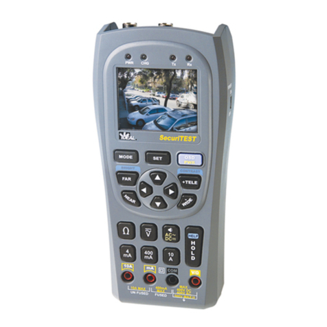
IDEAL SecuriTEST User manual

IDEAL

IDEAL SecuriTEST User manual

IDEAL Volt Sensor 61-063 User manual

IDEAL

IDEAL Volt Sensor 61-063 User manual

IDEAL 61-796 User manual

IDEAL

IDEAL 61-796 User manual

IDEAL VoltAware NCV User manual

IDEAL

IDEAL VoltAware NCV User manual

IDEAL 61-830 User manual

IDEAL

IDEAL 61-830 User manual

IDEAL 61-517 GFCI Use and care manual

IDEAL

IDEAL 61-517 GFCI Use and care manual

IDEAL VDV PRO 33-771 User manual

IDEAL

IDEAL VDV PRO 33-771 User manual

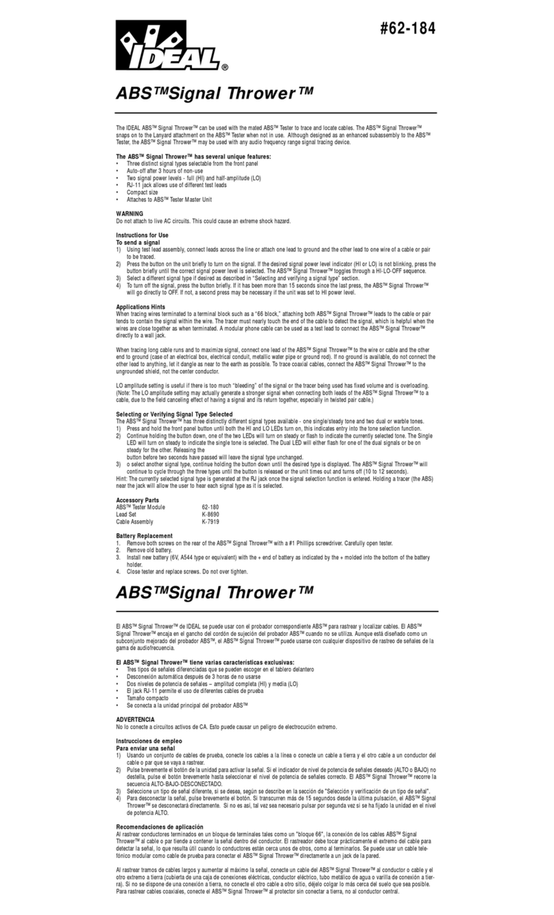
IDEAL ABS Signal Thrower 62-184 User manual

IDEAL

IDEAL ABS Signal Thrower 62-184 User manual

IDEAL Vol-Con 61-076 User manual

IDEAL

IDEAL Vol-Con 61-076 User manual

IDEAL 61-795 User manual

IDEAL

IDEAL 61-795 User manual

IDEAL OTDR User manual

IDEAL

IDEAL OTDR User manual

IDEAL 61-085 User manual

IDEAL

IDEAL 61-085 User manual

IDEAL 61-534 User manual

IDEAL

IDEAL 61-534 User manual

IDEAL Vol-Con Elite User manual

IDEAL

IDEAL Vol-Con Elite User manual

IDEAL 61-521 User manual

IDEAL

IDEAL 61-521 User manual

IDEAL SecuriTEST PRO Configuration guide

IDEAL

IDEAL SecuriTEST PRO Configuration guide

IDEAL 61-954 User manual

IDEAL

IDEAL 61-954 User manual

IDEAL 61-085 User manual

IDEAL

IDEAL 61-085 User manual

IDEAL ABS User manual

IDEAL

IDEAL ABS User manual

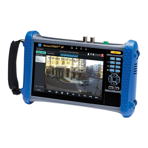
IDEAL SecuriTest IP User manual

IDEAL

IDEAL SecuriTest IP User manual

Popular Test Equipment manuals by other brands

LeCroy WAVESURFER Operator's manual

LeCroy

LeCroy WAVESURFER Operator's manual

Tektronix TDS 340 manual

Tektronix

Tektronix TDS 340 manual

AlcoMate Core Operator's manual

AlcoMate

AlcoMate Core Operator's manual

Hioki ST4030 instruction manual

Hioki

Hioki ST4030 instruction manual

IWH DI-3008 Operation manual

IWH

IWH DI-3008 Operation manual

Guangzhou Liwei FR2000+ user manual

Guangzhou Liwei

Guangzhou Liwei FR2000+ user manual

M-system Sentronic M5DY Series quick start guide

M-system

M-system Sentronic M5DY Series quick start guide

thomann STARVILLE LF-6 user manual

thomann

thomann STARVILLE LF-6 user manual

Rheintechnik HK operating instructions

Rheintechnik

Rheintechnik HK operating instructions

Tektronix MSO3000 Series user manual

Tektronix

Tektronix MSO3000 Series user manual

Tektronix MSO 5 Series Installation and safety manual

Tektronix

Tektronix MSO 5 Series Installation and safety manual

DeFelsko PosiTector 6000 FNDS Addendum to instruction manual

DeFelsko

DeFelsko PosiTector 6000 FNDS Addendum to instruction manual

Extech Instruments HDV540 user manual

Extech Instruments

Extech Instruments HDV540 user manual

Gamry Interface 1000 Operator's manual

Gamry

Gamry Interface 1000 Operator's manual

Buhler GAS 222.35 Installation and operation instruction

Buhler

Buhler GAS 222.35 Installation and operation instruction

Agilent Technologies N5230-60102 Installation note

Agilent Technologies

Agilent Technologies N5230-60102 Installation note

Weidmüller VT CTL operating instructions

Weidmüller

Weidmüller VT CTL operating instructions

Megger TDR2000/3 quick start guide

Megger

Megger TDR2000/3 quick start guide

manuals.online logo
manuals.online logoBrands
  • About & Mission
  • Contact us
  • Privacy Policy
  • Terms and Conditions

Copyright 2025 Manuals.Online. All Rights Reserved.