HE&M Hurricane 2030A User manual

1
OMRON CONTROL
TS OPERATIONS
FOR
HURRICANE
2030A SAWS

2
OPERATIONS
How to Energize the Saw
1. Pull the Main Disconnect lever located on the High Voltage Junction Box to the “ON”
position to energize the saw.
NOTE: It is recommended that this entire control operations section be
read completely before energizing the control. Follow the step by step
instructions below while working with the control and saw.
2. Verify that the “Emergency Stop” button located on top left corner of the
control console is raised up in the off position. (If it is pressed down, turn
the button clockwise to raise it.)
3. The “KEYLOCK” switch must be in the "NORMAL" position.
4. Turn the spring-loaded “POWER” switch to the “ON” position. This
energizes the programmable logic controller (PLC), which initiates the
touch screen program.
NOTE: Verify that all of the function switches on the control console are
in the green “STOP/AUTO” position. This position is indicted by the
green font on the switch name labels. (This is a safety feature; the saw
will not start if certain switches are not in the correct position.)

3
6. After the computer initializes, a “CAUTION” screen will appear. Please read the warnings
before proceeding.
.
7. After reading and understanding the
caution warnings, select the “I HAVE
READ THESE CAUTIONS AND I
WISH TO PROCEED” icon.
5. The following “Booting” screen will appear on the touch screen as shown below. While
the screen is booting all the console lights will flash for a brief period.
DO NOT OPERATE THIS MACHINE UNLESS YOU HAVE RECEIVED PROPER
INSTRUCTIONS.
SERIOUS INJURY OR DEATH MAY OCCUR IF OPERATED IMPROPERLY OR
IN AN UNSAFE MANNER.
NEVER PLACE YOUR HANDS OR ANY PART OF YOUR BODY IN THE
CUTTING AREA WHILE THE BLADE IS RUNNING.
ALWAYS WEAR GLOVES WHILE CHANGING OR HANDLING THE BLADE.
MAKE SURE ALL GUARDS AND PROTECTIVE EQUIPMENT IS IN PLACE.
MACHINE MAY MOVE UNEXPECTEDLY WHILE OPERATED IN AN
AUTOMATIC MODE!

4
8. The following screen will appear.
9. With all of the function switches on the control console still in the green “NORMAL” or
“STOP/AUTO” position the Hydraulic System can now be energized.
10. Turn the spring-loaded “POWER” switch to the “START” position.
The spring-loaded switch will return to the center “ON” position. The
light above the “POWER” switch will illuminate indicating that the
control is energized. When the “POWER” switch is activated, the
hydraulic pump will start and all control console switches will become
active.

5
13. A pop-up screen will appear on top of the Main Menu of the touch screen asking “Do you
wish to do a “Quick Cal.” at this time?”
14. By pressing the “YES” icon, the
“CONTROL PANEL” screen will appear
and allow for a Quick Calibration of the
Feed Encoder, Height Encoder and Miter
Encoder by following the prompts. (For
more information on Feed and Arm
Calibration refer to the “CONTROL
PANEL” section of the manual.)
15. After the Quick
Calibration is complete
the Main Menu screen
will appear. The Main
Menu screen presents the
operator with several
options of how to proceed.
Note: It is strongly recommended that the Quick Calibration procedure be followed each
time the control is energized or every 24 hours to ensure accuracy of the feed and arm
height.

6
Startup Bypass Procedure
The following procedure describes the “Startup Bypass Procedure” on any touch screen machine.
In the event that the touch screen doesn’t power up for any reason follow the step by step
procedure to power “ON” the hydraulic system.
1. Turn the Machine “OFF” by turning the spring-loaded “POWER” switch to the “OFF”
position and wait 30 seconds.
2. Hold the spring-loaded “POWER” switch in the “START” position and press the
“CONFIRM” button at the same time for 10 seconds.
3. Press the flashing “RESET” button to start the hydraulic System.
4. The machine will use a default blade speed and a default feed rate (for machines with HCCT)
to cut material.
5. The default rates must be set when the machine is being installed according to the customer
specifications.
6. The customer will have the ability to change the default rate parameters under the
“SUPERVISOR LEVEL 3” login.
7. Changing default values will not be included in the user manual. Please call HE&M Saw’s
service department for more information.
How to De-Energize the Control
The control circuit must be de-energized in a particular way if it is to remain de-energized for an
extended period of time, (over two hours). This will allow the saw to rest and not drift from
square or put strain on the hydraulic components.
1. Raise the arm.
2. Turn the “POWER” switch to the “OFF” position.
3. Turn the “KEYLOCK” switch to the “ENGAGED” position.
4. Press down the “Emergency Stop” Button.
NOTICE: The saw must be allowed to complete the cut through the material it is cutting or
the blade must be raised completely out of the material before the saw is de-energized. If the
saw is de-energized with the blade in the cut it may cause irreparable damage to the blade or
the saw and could void the warranty.
7
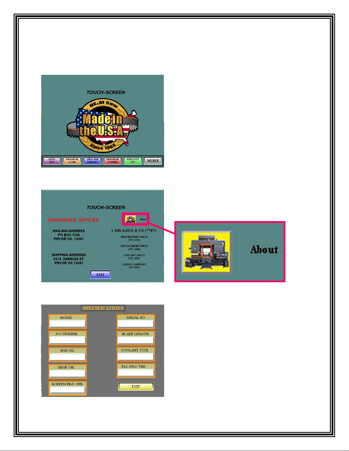
CONTACT INFORAMATION
To access important HE&M Saw phone
numbers, touch the Made in the U.S.A. logo on
the Main Menu and a screen will appear showing
contact information.
To access a list of specifications for the machine
select the “About” icon.
A list of specifications for the machine will
appear.

8
To access the security levels, touch
anywhere on the model number
located at the top of the Main Menu
screen.
A pop-up window will appear displaying the
different Security Levels. Each level adds the
ability to access additional options. To log in,
select a security level and another pop-up
window will appear asking for the password to
the Security Level selected. Enter the correct
password for the level requesting and select the
“OK” icon.
OPERATOR LEVEL 1 allows access to Parameter Settings 1. Parameter Settings 1 allows
access to the adjustments shown in these images.
NOTE: Some settings are “viewable only” and can only be changed with a Higher Level
Login or by the Factory.

9
PREVENTATIVE MAINTENANCE REMINDER
Normal wear and tear can result in lower machine efficiency. Preventative Maintenance
assures optimal working conditions and conserves the life span of the equipment. A planned
preventive maintenance may cause a small burden for production, but nothing compared to
downtime cause by an actual breakdown. All HE&M Saw machines are equipped with a
friendly reminder on when to schedule the next Preventative Maintenance Service
appointment for their machine.
The Main Menu screen
will have a “SERVICE
SOON” icon appear.
Select the “SERVICE SOON” icon and
this “SERVICE WARNING” will appear.
Select the “DONE” icon at the bottom of
the screen to return to the Main Menu.
The “SERVICE SOON” icon will continue to appear until the machine has been serviced.
Contact HE&M Saw service department @ (918)-824-6181to set up your preventative
maintenance appointment.

10
MAIN MENU – Screen Overview
AUTO RUN
This screen allows the operator to run a quick job once the job has been created in the job program screen.
The blade speed, quantity and any cutting operation options, such as extra vises, step feed, etc. can be
adjusted from this screen. Refer to the “Auto Run” section of this manual for further instructions.
PROGRAM A JOB
The operator can create a job program by inputting the desired blade pitch, blade speed, length, height,
and quantity. After creating a job program the operator can run it as a quick job or save it to the Job
Library to recall the information at a later time. Refer to the “Program a Job” section of this manual for
further instructions.
VIEW JOB LIBRARY
The Job Library displays information stored by the operator in an interactive data base that contains up to
1000 jobs including the “Quick Job”, along with specific job information such as length, quantity, blade
speeds, etc. It stores a list of programmed jobs that can be reviewed, edited, or called up to run, either as a
single job, or a series of jobs to be run in consecutive order. Refer to the “View Job Library” section of
this manual for further instructions.
PROGRAM A SERIES
To save time and material, the saw has the ability to run a sequence of up to 12 job numbers (cuts) in a
sequence up to 99 times using the “Program Series” icon. 100 sequences can be saved to recall at a later
time. The operator can enter the job information into the Series Overview screen to create these
sequences. There must be jobs programmed in the “JOB LIBRARY” to program a series. Refer to the
“Program A Series” section of this manual for further instructions.
SEMI AUTO CUT
The Semi Auto Cut allows the operator to make a single, semi-automatic cut without creating a job
number or a job program. This is a good option when performing a one-time cut. Refer to the “SEMI
AUTO CUT” section of this manual for further instructions.
MORE
The “MORE” icon provides access to additional setting and features. The operator can adjust settings for
various functions such as arm and feed calibration, review information on the blade life and motor hours,
or access help files that give instructions on changing the saw blade. Refer to the “Control Panel” and
“Help Files” section of this manual for further instructions.
11
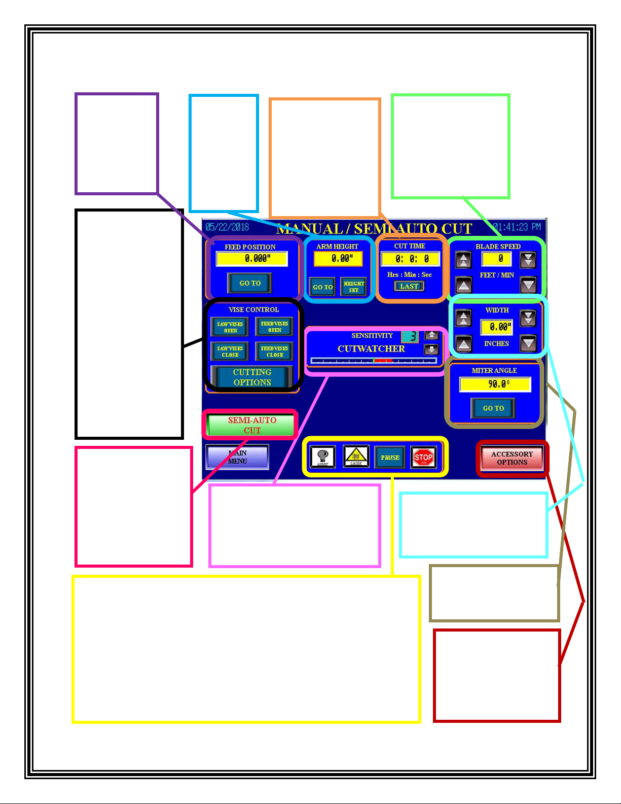
MANUAL/SEMI AUTO CUT – Screen Overview
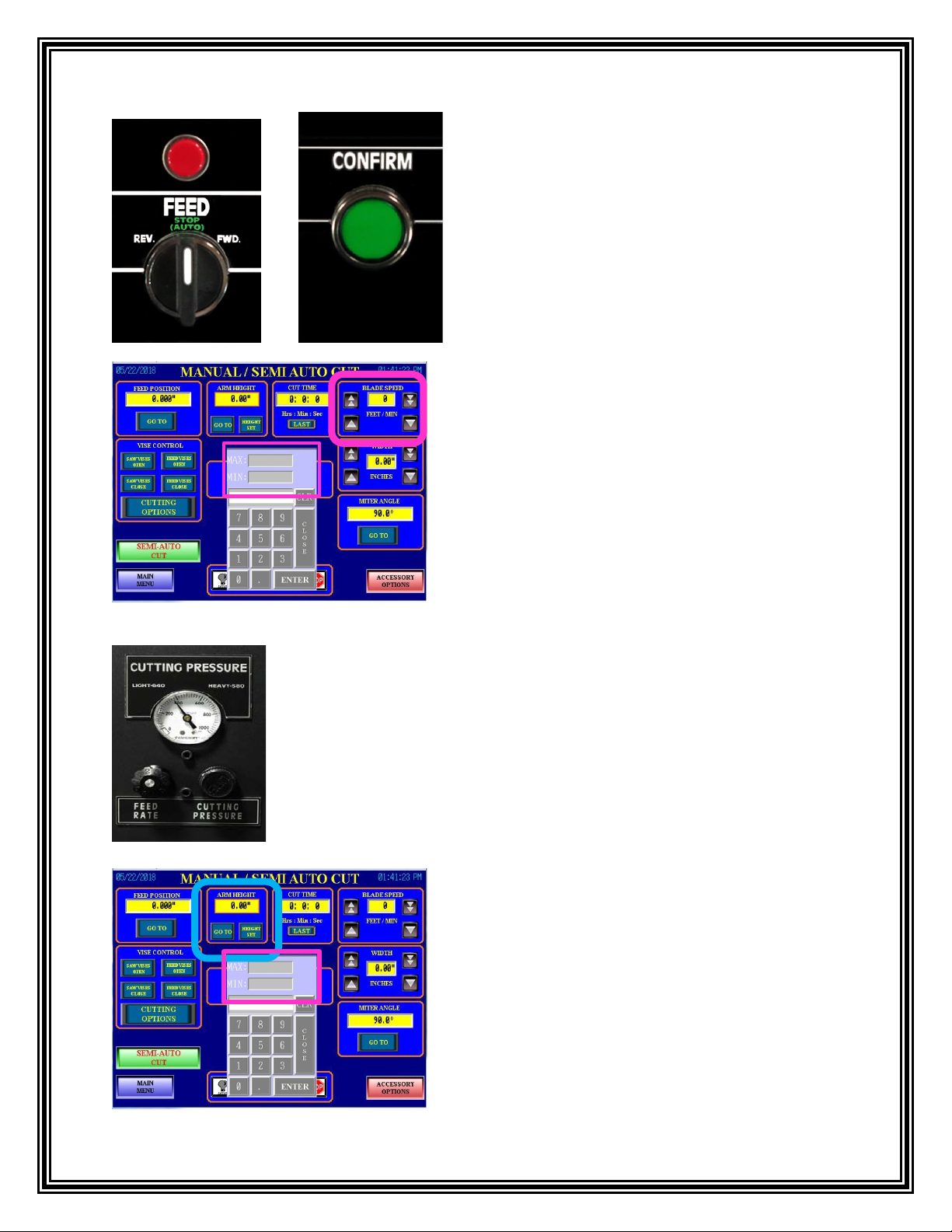
FEED
POSITION:
Places the feed
into the desired
position before
a cut.
BLADE SPEED:
Displays the Blade
Speed in feet per
minute. This can be
adjusted using the
arrow keys or through
the numeric input.
CUT TIME:
Displays the time
recorded for the
current cut. By
pressing the “LAST”
icon it will show the
time recorded for the
previous cut.
ARM
HEIGHT:
Places the
arm at the
desired
height
before a
cut.
MITER ANGLE: Places
the arm to the desired
angle before a cut.
WORK LIGHT: Turns on or off the work light.
LASER LIGHT: (Optional) Turns the Laser Light on or off. When the laser
alignment beam is activated, the work light will automatically turn off to allow
better laser visibility.
PAUSE: By selecting this, it will pause the active cutting cycle. The operator
will be able to resume the cut by selecting the icon again.
STOP: Stops the cut in progress and cannot restart without restarting the
process.
SEMI-AUTO CUT:
Press “SEMI-AUTO
CUT” and the
“CONFIRM” button to
make a cut in the
material. The Semi-
Auto icon will now
read “CUTTING”.
VISE CONTROL:
Operator is able to
open or close the
selected Saw Vise
and the Feed Vise by
selecting either the
open or close icons.
CUTTING
OPTIONS: Allows
the operator to select
various aspects of
saw operation such as
Vise Selection, Arm
Retract, and Cut
Watcher.
ACCESSORY
OPTIONS:Select to
access the Coolant, Chip
Auger, and other various
option settings. (For more
information refer to the
CUT WATCHER: The Cut watcher
displays when the saw is cutting out
of square. The sensitivity level can
be adjusted using the arrows or
through the numeric input.
WIDTH: Displays the width
of the material. This can be
adjusted using the arrow keys
or through the numeric input.
12
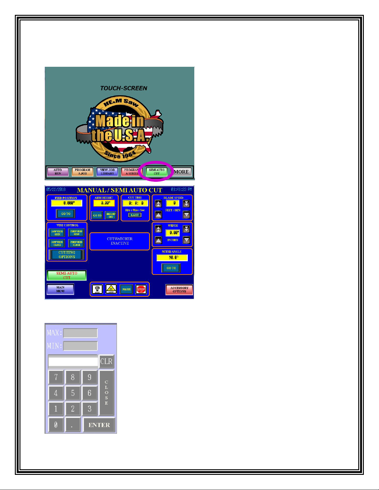
Semi Auto Cut
1. Press the “SEMI AUTO CUT” icon on
the Main Menu.
NOTE: The “CONFIRM” button is used
in conjunction with many of the saw’s
operations. When performing an
operation that works in conjunction with
the “CONFIRM” button the
“CONFIRM” button will flash and light
up to indicate that it must be pressed
while performing the operation.
2. The “MANUAL/SEMI AUTO CUT”
screen will appear. This screen allows for
adjustments to the cutting operation.
NOTE: Most operations will allow the operator to change the
job parameters by touching the numerical box. This will open a
pop-up keypad that allows the operator to enter in new job
parameters. The keypad will have a Minimum and Maximum
value displayed at the top. The keypad will not allow the
operator to enter a number and continue the process if the value
entered is higher or lower than what is displayed in the “MAX”
and “MIN” fields.
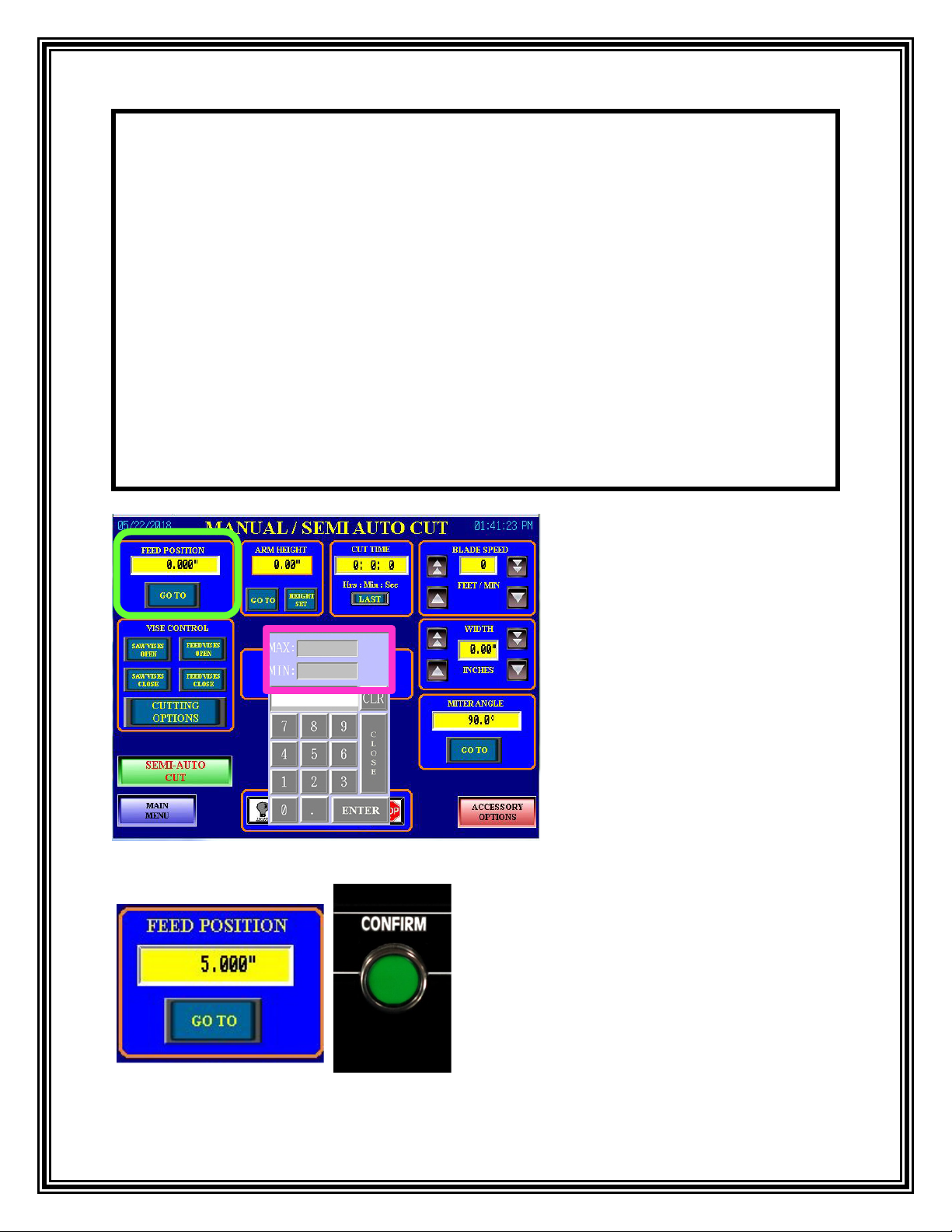
13
3. To adjust the feed shuttle
position select the numerical box
in the “FEED POSITION”
window and a pop-up keypad will
appear. Input the desired length
and select the “ENTER” icon.
The new feed position value will
display and the keypad will
disappear.
MAX – Table Length
MIN - 0
4. Press the “GO TO” icon on the touch
screen and the “CONFIRM” button on the
control console at the same time and the
feed shuttle will adjust to the position
entered.
Note:
HE&M Saw machines with the Omron touch screen have strict safety controls.
Therefore every pinch point operation is a “Two Hand” operation. This means the
operator must initiate the desired operation and press the “CONFIRM” button at the
same time.
Pinch Point Operations are:
•Vises “OPEN” and “CLOSE”
•Arm “RAISE” and “LOWER”
•Guide “OUT” and “IN”
•Feed shuttle “FORWARD” and “RETRACT”
•Turning Motor “ON”
•Turning the Chip Removal System “ON”
•Starting a Manual/Semi Auto Cut
•Miter Angle “INCREASE” and “DECREASE”
14
6. To adjust the Blade Speed use the arrows in
the “BLADE SPEED” window. Using the
single up and down arrows will increase or
decrease the blade speed by 1. Using the
double up and down arrows will increase or
decrease the blade speed by 10’s. Or select the
numerical box in the middle of the arrows and
a pop-up keypad will appear. Input the desired
blade speed and select the “ENTER” icon and
the keypad will disappear.
MAX – 300
MIN - 60
8. To adjust the arm height select the numerical
box under the “ARM HEIGHT” window and a
pop-up keypad will appear. Input the desired arm
height and select the “ENTER” icon. The new
arm target position value will be displayed and
the keypad will disappear.
MAX – Maximum height of the machine
MIN- 0.5
7. “Knobs and Gauges” are used to set the “FEED RATE” and
“CUTTING PRESSURE” (Traverse Control). For more
information refer to the Feed Rate and Cutting Pressure section in
this manual.
5. To adjust the feed shuttle position
manually use the “FEED” switch and the
“CONFIRM” button located on the control
console to move the feed forwards or
backwards.

15
10. To adjust the arm height manually move the
spring-loaded “ARM” joystick on the control
console up into the “RAISE” position while
pressing the “CONFIRM” button. Hold the
“ARM” joystick in the “RAISE” position until the
appropriate height has been reached the operator
can let go of the spring-loaded “ARM” joystick
and it will return to the “STOP/AUTO” position.
9. Then press the “GO TO” icon on the touch
screen and the “CONFIRM” button on the control
console at the same time. Once the arm has
reached the arm height position previously entered
the arm will stop moving and the operator can
select the “HEIGHT SET” icon. This will set the
height that the arm will return to after each cut.
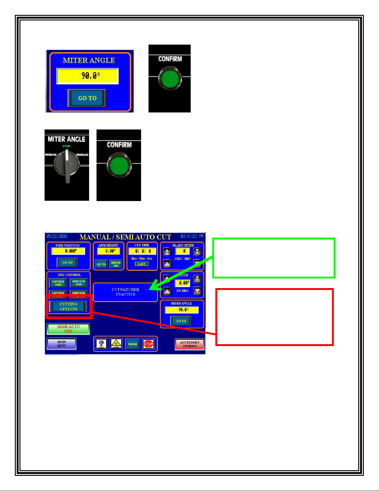
12. To adjust the miter angle select the
numerical box in the “MITER ANGLE”
window and a pop-up keypad will appear.
Input the desired angle and select the
“ENTER” icon. The new angle will be
displayed and the keypad will disappear.
MAX – 90°
MIN- 30°
11. Press the “HEIGHT SET” icon on the touch screen. This will
set the height that the arm will return to after each cut and now the
present arm height will be displayed.
16
Cut Watcher: Monitors blade deviation, and is useful in detecting when the blade begins to cut
dull and/or starts cutting out of square. A sensor mounted on the adjustable guide arm is
connected to a precision carbide guide that rides on one side of the saw blade. If the blade begins
to deviate at any time, a digital display on the touch screen panel will indicate the deviation. As
the saw blade continues to dull, the deviation may increase. The readout on the screen is helpful
to detect a cutting problem due to a dull blade or over-feeding the saw blade through the
material. For more information, refer to the Cut Watcher section in this manual. NOTE: The Cut
Watcher is not a standard feature on all saw models.
16. To activate the cut watcher,
select the “CUTTING OPTIONS”
icon. The “MANUAL/SEMI
AUTO CUTTING OPTIONS”
screen will appear.
15. This image shows the “CUT
WATCHER” is currently
“INACTIVE”.
13. Press the “GO TO” icon on the touch
screen and the “CONFIRM” button on
the control console at the same time and
the arm will adjust to the angle entered.
14. To adjust the Miter Angle manually use the
“MITER ANGLE” switch and the “CONFIRM”
button located on the control console to increase or
decrease the degree of the angle.
17
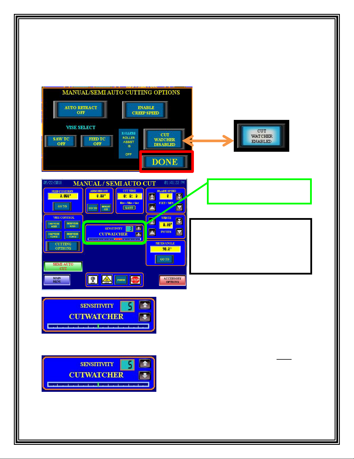
17. To “Enable” the Cut Watcher select the “CUT WATCHER DISABLED” icon. The icon
will now show “CUT WATCHER ENABLED”. Then select the “DONE” icon. The
“MANUAL/SEMI AUTO CUTTING OPTIONS” screen will close.
18. The Cut Watcher function is
now enabled and active.
20. When the Cut Watcher centerline is NOT
displaying a red bar to either one side or the other,
this indicates that the Cut Watcher is calibrated
and the blade is cutting straight as shown in this
image. This is the desired appearance that is
obtained by adjusting the Cut Watcher after a new
blade is installed.
19. The Operator can now use the ↑↓ arrows to
adjust the sensitivity of the Cut Watcher. Or they
can select the numerical box and input the number
of sensitivity from the pop-up keypad.
Note: The Cut Watch Sensitivity is in
the lowest degree of sensitivity when
it is set to a “1” and the highest
degree of sensitivity when it is set to
a “10” on the touch screen control.
18
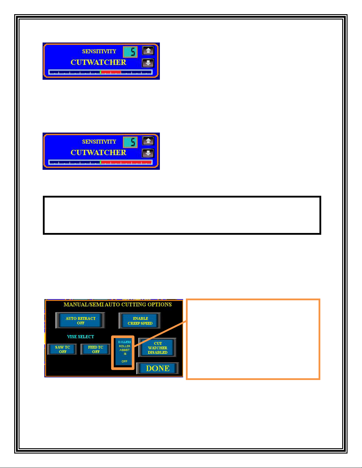
23. From the “MANUAL/SEMI AUTO CUTTING OPTIONS” screen the operator will be
able to activate or deactivate certain features (if available) from this screen. Select the
“CUTTING OPTIONS” icon from the “MANUAL/SEMI AUTO CUT” screen.
22. This image shows the red bar illuminated all the
way to the right of the center. If this condition
remained for approximately 20 seconds while the
saw is cutting, the Cut Watcher function will go into
panic mode.
21. If the blade deviates from cutting straight, a
bar on the appropriate side will appear, indicating
the relative amount of deviation. In this image the
Cut Watcher is starting to read out-of-square with
two red bars to the right of the center. The bar will
grow progressively as the sensor detects deflection
of the blade to either side of the center.
NOTE: Some of the icons shown on the “MANUAL/SEMI AUTO CUTTING
OPTIONS” screen are optional and do not come standard with all saw
models.
ROLLER ASSIST INDICATOR: The
Roller Assist indicator displays if the
roller assist feature is currently ON or
OFF. This feature is controlled from the
“ACCESSORY OPTIONS” screen. Refer
to the “CONTROL PANEL” section of
this manual for further information on
using the Roller Assist.
19
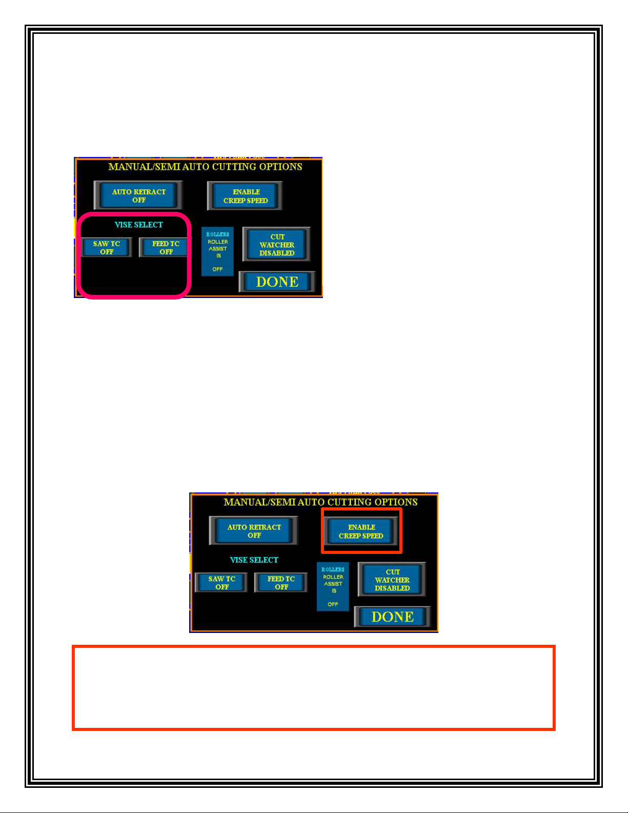
VISE SELECT: The “MANUAL/SEMI AUTO CUTTING OPTIONS” screen allow the
operator to select (or de-select) other vises which may be optionally mounted on the saw system.
These include the discharge vise located on the discharge table, the 3rd vise mounted near the end
of the feed table, and top clamps mounted on the saw, feed, and discharge.
ENABLE CREEP SPEED: The Creep Speed is a function that slows the feed shuttle speed
down when moving material into the cutting. This function is useful when positioning material to
make a Trim Cut. The Creep Speed can also be used to slow the tilt speed down when mitering
the saw blade. This is useful when positioning the blade into the correct position. Once the Creep
Speed is enabled hold the spring-loaded “FEED” switch and the “CONFIRM” button on the
control console at the same time to move the feed/material forwards or backwards at a slower
rate. Or hold the “MITER” switch with the “CONFIRM” button on the control console at the
same time to miter the blade left or right at a slower rate.
24. Under “VISE SELECT” the operator
will be able to select the appropriate icon to
turn “ON” or “OFF” any optional vises or
top clamps. Turning an optional vise or top
clamp “ON” will allow it to open and close
in conjunction with the Main Saw Vise for
a Semi Auto Cut.
25. Select the “ENABLE CREEP SPEED” icon and the speed for the miter or feed will slow
down so the stopping point for either will be more precise. The icon will now read “CREEP
SPEED ENABLED”. To return the miter or feed to the normal speed select the “CREEP
SPEED ENABLED” icon. The “FEED” or “MITER” switch will return to the original speed.

20
AUTO RETRACT: At the end of the Semi Auto Cut, the blade will stop turning. The operator
has the option of leaving the blade down at the end of the cut or automatically retracting the arm
to the home position using the “AUTO RETRACT” icon. While the arm is retracting the blade
will run in a slow “AUTO IDLE” speed.
26. Select the “AUTO RETRACT OFF”
icon and the icon will now read “AUTO
RETRACT ON”. This will activate the auto
retract feature so the arm is automatically
retracted to the home position after each cut.
Select the “AUTO RERACT ON” icon and
it will now read “AUTO RETRACT OFF”
this will deactivate the auto retract feature
and leave the blade down in the cut.
27. After the operator has made the necessary adjustments to the cutting operations, place the
material onto the cutting area. Verify that the material is lying flat and up against the fixed
side of the vise. If required, open the “SAW VISE” and the “FEED VISE” to allow the
material to pass through. This can be accomplished by pressing the icons located in the
“VISE CONTROL” window on the touch screen or by using the “SAW VISE” AND “FEED
VISE” switches located on the control console. When using the spring-loaded “SAW VISE”
switch and “FEED VISE” switch the operator must hold the switch in the “OPEN” or
“CLOSE” position while pressing the “CONFIRM” button.
Table of contents
Other HE&M Saw manuals


