Heat & Cool TSTATCCPQ501 User manual

Installation Instructions
TSTATCCPQ501
TSTATBBPQ501
P474-1035
Digital Thermostat
NOTE: Read the entire instruciton manual before starting the installation.
72 72
I2:00
SET
AM
Tu
COOL
HEAT
&
Form: IM-TSTAT-22 Cancels: New Printed in U.S.A. Catalog No. 63TS-TA12
5+2 DAY PROGRAMMABLE
1-STAGE HEAT, 1-STAGE COOL
Table Of Contents
PREPARATION
Page 1
3
4
14
7
SAFETY WARNINGS
2
REMOVE OLD THERMOSTAT
WIRE CONNECTIONS
JUMPER CONFIGURATION
TEST OPERATION
TROUBLESHOOTING
17
18
Patents Pending 4/03
5
INSTALLATION AND BATTERY
REPLACEMENT

Safety Warnings
Page 2
CAUTION Follow Installation Instructions carefully.
DISCONNECT POWER TO THE HEATER -
AIR CONDITIONER BEFORE REMOVING
THE OLD THERMOSTAT AND INSTALLING
THE NEW THERMOSTAT.
WARNING
The 2 Alkaline “AA” batteries must be replaced at least
every 12 months to assure proper operation.
The thermostat will display the Low Battery
code (fig. 1) on the display of the thermostat
when it is time to replace the batteries. If the
thermostat is connected to 24v power, the
Batteries may still be installed, but are not required.
When is displayed the batteries must be replaced
within 5 days. The manufacturer cannot be liable for
improper operation of the thermostat if the batteries are
not replaced within this time period.
The annual battery replacement is especially critical in
locations subject to freezing temperatures. The
thermostat will be unable to turn on the Heat if the
batteries are exhausted.
CAUTION
FIG. 1
This device complies with Part 15 of the FCC rules.
Operation is subject to the following 2 conditions:
(1) This device may not cause harmful interference, and (2)
This device must accept any interference received, including
interference that may cause undesired operation.
Step #1 Preparation
Page 3
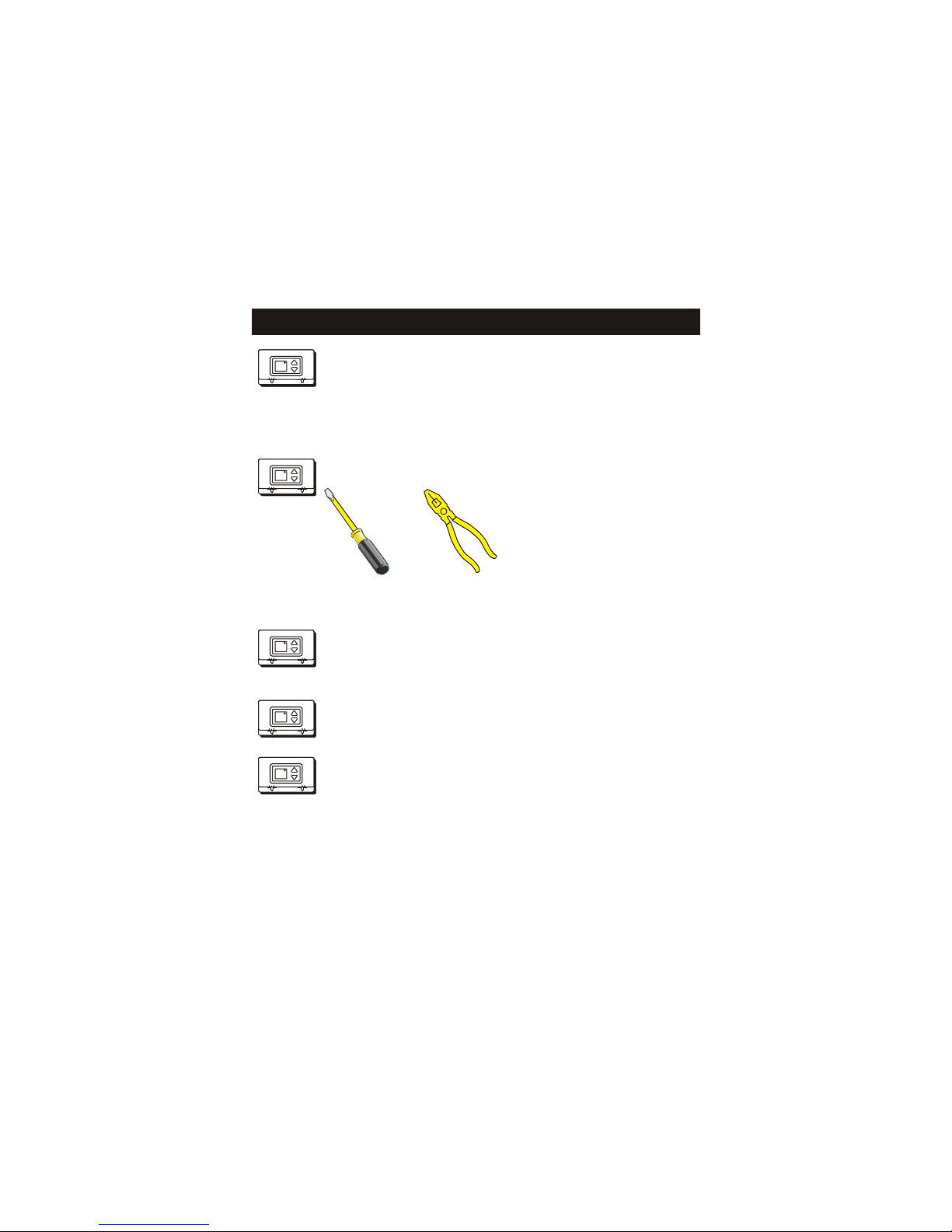
These tools will be required:
Flat Blade
Screwdriver
Wire cutter
& Stripper
Make sure your Heater/Air Conditioner
is working properly before beginning
installation of the thermostat.
Carefully unpack the thermostat.
Save the screws and instructions.
Turn off the power to the Heating/Air
Conditioning system at the main fuse
panel. Most residential systems have
a separate breaker for disconnecting
power to the furnace.
Proper installation of the thermostat will be
accomplished by following these step
by step instructions. If you are unsure
about any of these steps, call a qualified
technician for assistance.
72
Heat Off Cool FanOn
FanAuto
72
Heat Off Cool FanOn
FanAuto
72
Heat Off Cool FanOn
FanAuto
72
Heat Off Cool FanOn
FanAuto
72
Heat Off Cool FanOn
FanAuto

Page 4
Step #2 Remove & Replace Old Thermostat
Remove the cover of the old thermostat.
If it does not come off easily check for
screws.
Loosen the screws holding the thermostat
base or subbase to the wall, and lift away.
Disconnect the wires from the old
thermostat. Tape the ends of the wires
as you disconnect them, and mark them
with the letter of the terminal for easy
reconnection to the new thermostat.
Keep the old thermostat for reference
purposes, until your new thermostat is
functioning properly.
72
Heat Off Cool FanOn
FanAuto
72
Heat Off Cool FanOn
FanAuto
72
Heat Off Cool FanOn
FanAuto
72
Heat Off Cool FanOn
FanAuto

Open The New Thermostat
The top of the thermostat housing has two (2) screw-
driver slots to assist when separating.
Repeat the procedure in the other screw driver slot.
Separate the housing halves by pulling the top
forward until the pins release, and then lift the bottom
out.
To pull the housing apart, insert a small blade screw-
driver into the slot and rotate 90 . This will release
the top housing snaps.
SCREWDRIVER
SLOTS
The batteries must be replaced
within 5 days when the thermostat
displays the Low Battery code (fig.1). L8 FIG. 1
Page 5
Step #3 Installation and Battery Replacement
Page 6
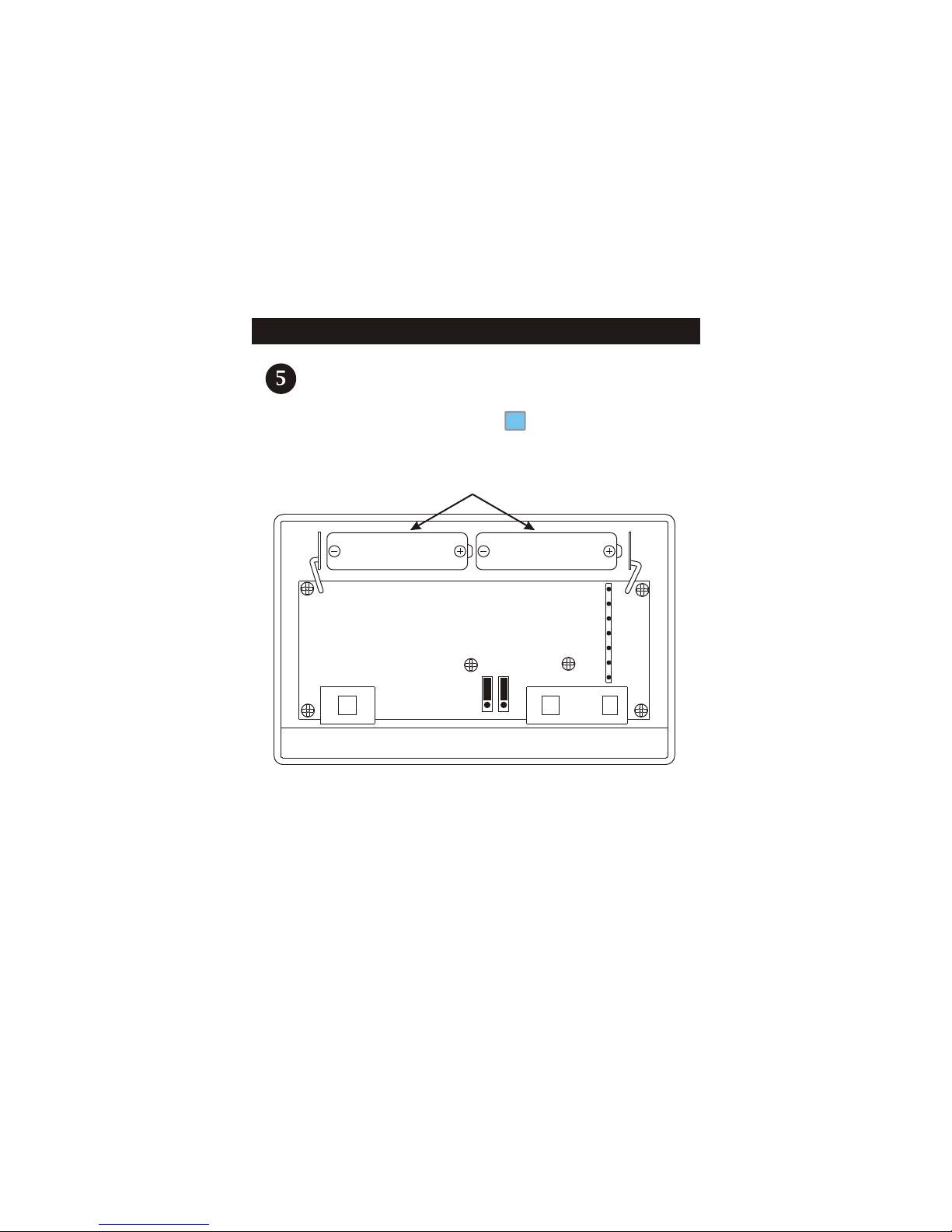
Battery Replacement
IF THE THERMOSTAT IS NOT SYSTEM POWERED REPLACE
WITH ALKALINE BATTERIES AT LEAST ONCE EVERY YEAR,
OR WHEN THE “LOW BATTERY” ICON APPEARS
(pages 2,5).
L8
POSITION BATTERIES AS SHOWN
USE “AA” SIZE
ALKALINE BATTERIES USE “AA” SIZE
ALKALINE BATTERIES
ELEC GAS
HP GAS

If the terminal designations on your old
thermostat do not match those on the
new thermostat, refer to the chart below,
or the wiring diagrams that follow.
Wire from the
old thermostat
terminal marked Function
Install on the
new thermostat
connector marked
Y1 or Y Cooling Y
PowerRh, R, M, Vr, A R
B
BRev. Valve
(Energize to Heat)
W1, W or H Heating W
G or F Fan G
O
Rev. Valve
(Energize to Cool)
O
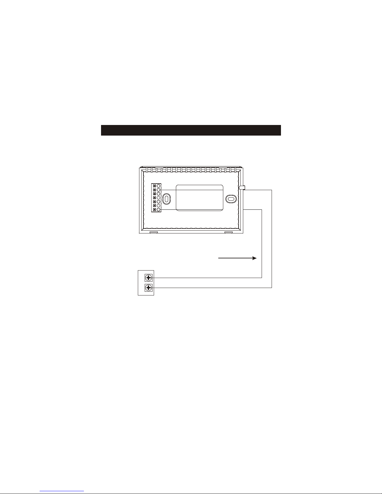
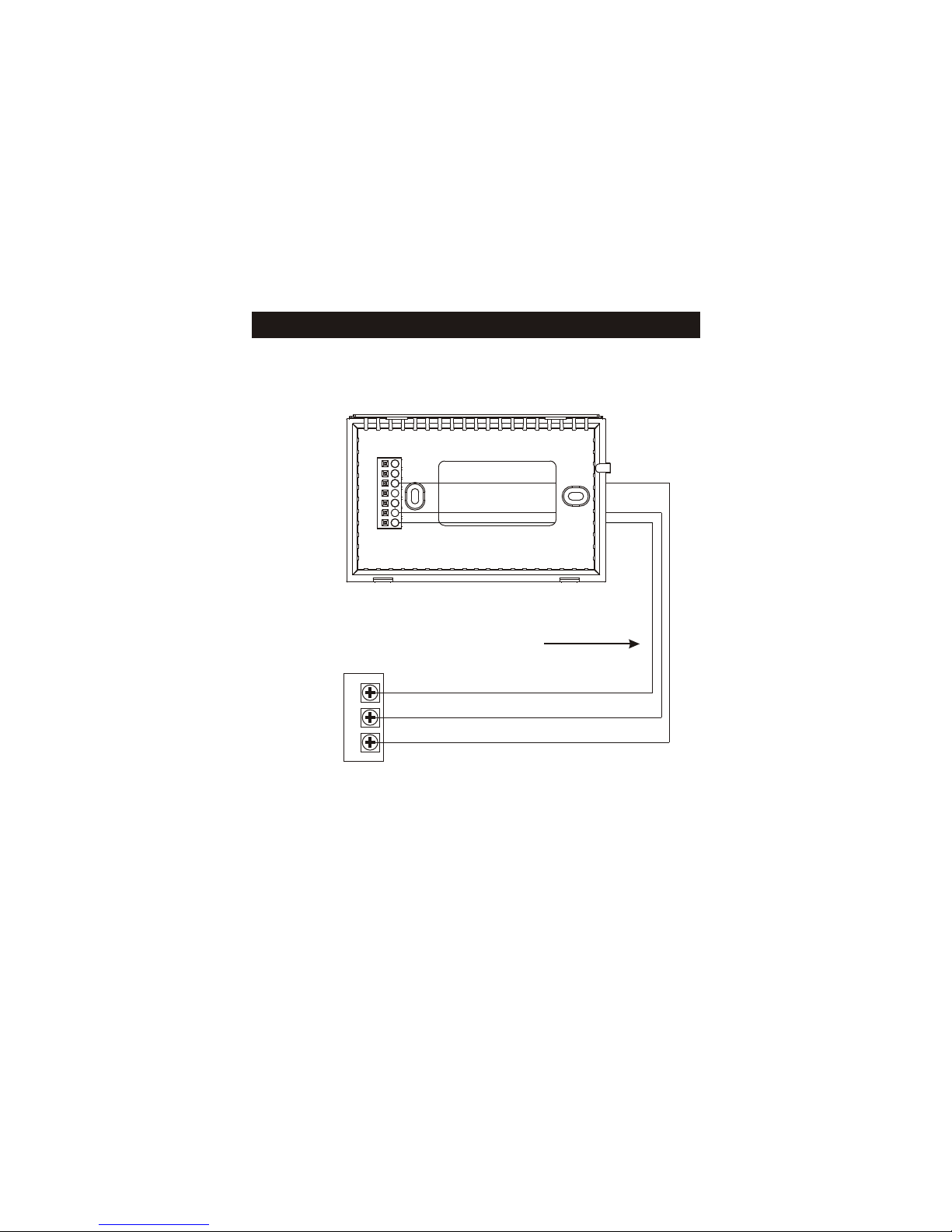
A label is provided on the backplate
that prevents drafts, originating inside
the wall, from entering the thermostat.
These drafts, left unchecked, may
cause incorrect room temperature
readings.
Please do not remove this label
from the thermostat. Insert the wires
through the slots provided in the label
as shown in Fig. 1
Thermal Insulating Sheet
Fig. 1
Wire Slots
CCommon C (optional)
Page 7
Step #4 Wire Connections
72
Heat Off Cool FanOn
FanAuto
4Z95 97061606
MADE IN CHINA
USE SIZE “AA”
ALKALINE BATTERIES
W
Y
B
O
G
R
C
MODEL:

GAS OR
ELECTRIC HEAT
FAN
COOLING
POWER
WGRY
4 Conductor 18 to 22 gauge
unshielded cable from the
thermostat to the equipment.
4 Wire, 1 Stage Cooling, 1 Stage
Gas or Electric Heat
Residential Gas or Electric Heat *,
Electric Cool, split systems & package
units
W
Y
B
O
G
R
C
Common wire optional *
Common wire is optional in all installations. If a common wire is not used the
thermostat must be powered by the two AA Alkaline batteries (page 6). These
batteries must be replaced each year or when the Low Battery indicator is
displayed (page 2, 5).
*
Sample Wiring Diagrams
Page 8

4 Wire, 1 Stage Cooling, 1 Stage Heat-Heat Pump with O reversing valve*.
Residential Heat Pumps, split systems & package units, with no auxiliary heat.
FAN
POWER
GR
COMPRESSOR
Y
4 Conductor 18 to 22 gauge
unshielded cable from the
thermostat to the equipment.
REVERSING VALVE
O
W
Y
B
O
G
R
C
Common wire optional **
**
Sample Wiring Diagrams
Page 9
Common wire is optional in all installations. If a common wire is not used the
thermostat must be powered by the two AA Alkaline batteries (page 6). These
batteries must be replaced each year or when the Low Battery indicator is
displayed (page 2, 5).
*See page 14 regarding jumper configuration.

4 Wire, 1 Stage Cooling, 1 Stage Heat-Heat Pump with B reversing valve*.
Residential Heat Pumps, split systems & package units, with no auxiliary heat.
REVERSING VALVE
COMPRESSOR
FAN
POWER
GRY
W
Y
B
O
G
R
B
C
Common wire optional **
Sample Wiring Diagrams
Page 10
**Common wire is optional in all installations. If a common wire is not used the
thermostat must be powered by the two AA Alkaline batteries (page 6). These
batteries must be replaced each year or when the Low Battery indicator is
displayed (page 2, 5).
*See page 14 regarding jumper configuration.
4 Conductor 18 to 22 gauge
unshielded cable from the
thermostat to the equipment.

FAN
POWER
GR
W
3 Wire, 1 Stage Heat Residential Gas or Electric Heat units
with a separately controlled fan.
W
Y
B
O
G
R
C
Common wire optional *
*
Sample Wiring Diagrams
Page 11
Common wire is optional in all installations. If a common wire is not used the
thermostat must be powered by the two AA Alkaline batteries (page 6). These
batteries must be replaced each year or when the Low Battery indicator is
displayed (page 2, 5).
GAS OR
ELECTRIC HEAT
3 Conductor 18 to 22 gauge
unshielded cable from the
thermostat to the equipment.
POWER
WR
2 Wire, 1 Stage Gas Heat Residential Gas or Millivolt units.
W
Y
B
O
G
R
C
Common wire optional *
*
Sample Wiring Diagrams
Page 12
Common wire is optional in all installations. If a common wire is not used the
thermostat must be powered by the two AA Alkaline batteries (page 6). These
batteries must be replaced each year or when the Low Battery indicator is
displayed (page 2, 5).
GAS OR
ELECTRIC HEAT
2 Conductor 18 to 22 gauge
unshielded cable from the
thermostat to the equipment.
FAN
POWER
GRY
3 Wire, 1 Stage Cooling Residential Electric Cool units
W
Y
B
O
G
R
C
Common wire optional *
*
Sample Wiring Diagrams
Page 13
Common wire is optional in all installations. If a common wire is not used the
thermostat must be powered by the two AA Alkaline batteries (page 6). These
batteries must be replaced each year or when the Low Battery indicator is
displayed (page 2, 5).
3 Conductor 18 to 22 gauge
unshielded cable from the
thermostat to the equipment.
COOLING
IF THERMOSTAT IS NOT SYSTEM POWERED
REPLACE WITH ALKALINE BATTERIES ONCE EVERY YEAR
USE “AA” SIZE
ALKALINE BATTERIES USE “AA” SIZE
ALKALINE BATTERIES
ELEC GAS
HP GAS
Page 14
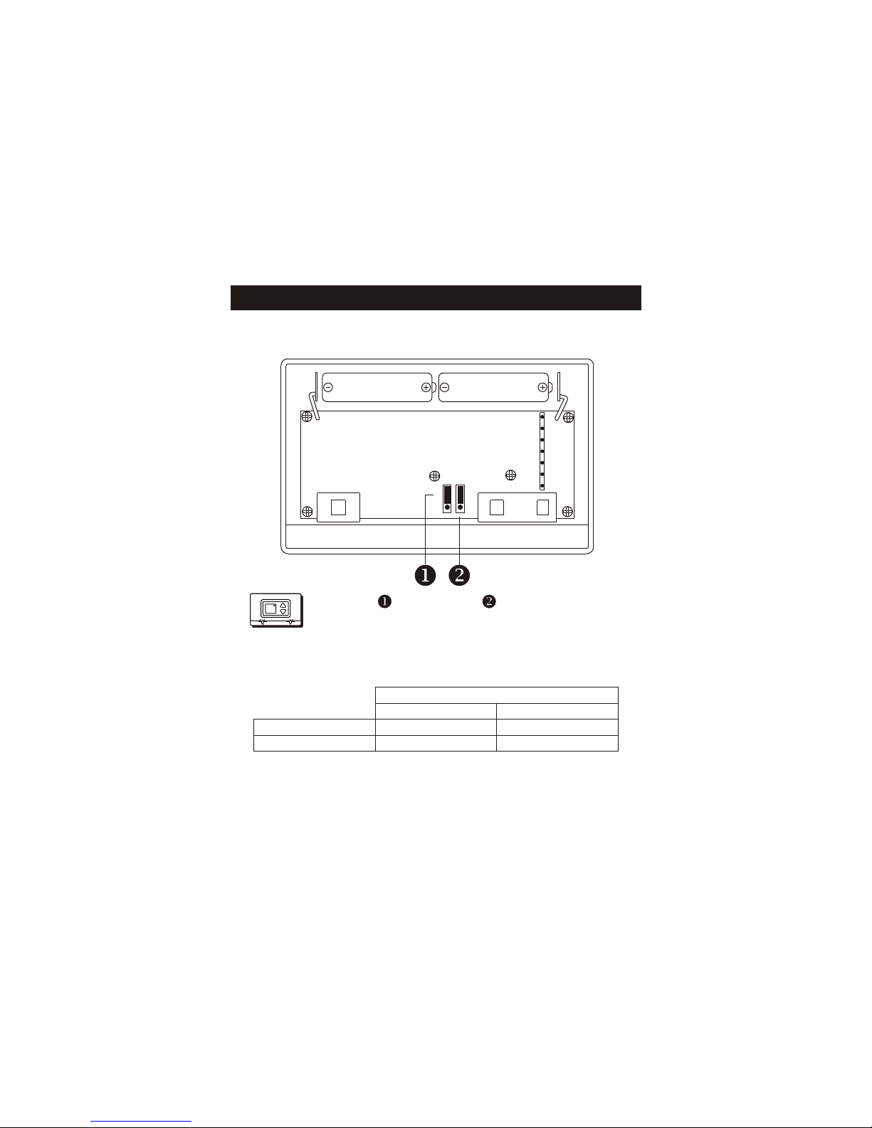
Step #5 Jumper Configuration
Figure-A)
Jumper and Jumper are shown in the
factory default positions for typical gas
furnace heating with electric cooling.
72
Heat Off Cool FanOn
FanAuto
*Outputs active - For normal operation do not connect to equipment
OUTPUTS
No Demand With Demand
Cooling Mode
Heating Mode
O* Y, G, O*
B* W, B*

IF THERMOSTAT IS NOT SYSTEM POWERED
REPLACE WITH ALKALINE BATTERIES ONCE EVERY YEAR
USE “AA” SIZE
ALKALINE BATTERIES USE “AA” SIZE
ALKALINE BATTERIES
ELEC GAS
HP GAS
Page 15
Step #5 Jumper Configuration
Figure-B)
72
Heat Off Cool FanOn
FanAuto
*Outputs active - For normal operation do not connect to equipment
OUTPUTS
No Demand With Demand
Cooling Mode
Heating Mode
O* Y, G, O*
B* W,G, B*
Jumper is used to select Fan On (G)
with Heat (W). Jumper shown in the
factory default position.

IF THERMOSTAT IS NOT SYSTEM POWERED
REPLACE WITH ALKALINE BATTERIES ONCE EVERY YEAR
USE “AA” SIZE
ALKALINE BATTERIES USE “AA” SIZE
ALKALINE BATTERIES
ELEC GAS
HP GAS
Page 16
Step #5 Jumper Configuration
Figure-C)
72
Heat Off Cool FanOn
FanAuto
OUTPUTS
No Demand With Demand
Cooling Mode
Heating Mode
O* Y, G, O*
B** Y ,G, B**
Jumper and Jumper are used to select
heat pump operation. Note: Thermostat
Does Not Have Auxiliary Heat / Emergency
Heat Capability. Leave jumpers in original
factory default positions (figure-A) for non
heat pump applications.
* Output active in Cooling
** Output active in Heating
Y active in Heating

Adjust the Slide Switch until it is located
under the word HEAT on the thermostat.
Press the Up or Down buttons until the set
temperature is 10 degrees above room
temperature. The HVAC unit should
energize in the heating mode.
Adjust the Slide Switch until it is located
under the word COOL on the thermostat.
Press the Up or Down buttons until the set
temperature is 10 degrees below room
temperature. The HVAC unit should
energize in the cooling mode.
Turn on the power to the Heating/Air
Conditioning system.
Adjust the Slide Switch until it is located
under the word OFF. Adjust the other slide
switch until it is located under the word Fan
On. The fan should turn on and run
continuously.
Page 17
Step #6 Test Operation
72
Heat Off Cool FanOn
FanAuto
72
Heat Off Cool FanOn
FanAuto
72
Heat Off Cool FanOn
FanAuto
72
Heat Off Cool FanOn
FanAuto

Page 18
Troubleshooting
SYMPTOM: The backlight on the thermostat
doesn’t stay on continuously, it only stays
on for 10 seconds after a button press.
CAUSE: The backlight is turned OFF in Advanced
Setup or a common wire is not connected.
REMEDY: To turn ON the backlight see Advanced
Setup on page 16 or 17 of the Owner’s Manual.
To connect a common wire see pages 8-13
of this manual.
SYMPTOM: The slide switches on the thermostat
are very difficult to move.
CAUSE: The backplate of the thermostat is
deformed by being screwed tightly into a
wall that is not perfectly flat.
REMEDY: Loosen the screws holding the
thermostat into the wall.
72
Heat Off Cool FanOn
FanAuto
72
Heat Off Cool FanOn
FanAuto

SYMPTOM: The air conditioning does not
attempt to turn on.
CAUSE: The cooling setpoint is set too
high or the Mode Switch is not set for
Cool, or the batteries are too weak.
REMEDY: Consult the Normal Operation
section of this manual to lower the
cooling setpoint and to correct the
Mode Switch position, or replace
the batteries.
SYMPTOM: The heating does not attempt
to turn on.
CAUSE: The heating setpoint is set too
low or the Mode Switch is not set for
Heat, or the batteries are too weak.
REMEDY: Consult the Normal Operation
section in this manuals to raise the
heating setpoint and to correct the
Mode Switch position, or replace
the batteries.
Page 19
Troubleshooting
72
Heat Off Cool FanOn
FanAuto
72
Heat Off Cool FanOn
FanAuto
This manual suits for next models
2
Table of contents


