manuals.online logo
Brands
  1. Home
  2. •
  3. Brands
  4. •
  5. Heat & Glo
  6. •
  7. Indoor Fireplace
  8. •
  9. Heat & Glo i30-X User manual

Heat & Glo i30-X User manual

i30-X Freestanding
Assembly Instructions
Further information can be found at:
https://jetmastervic.com.au/brochures-specifications/
These instructions are to be used in conjunction with the general i30-X installation manual that is
shipped with the unit.
DO NOT PLACE ARTICLES ON OR AGAINST THIS APPLIANCE
DO NOT USE OR STORE FLAMMABLE MATERIALS NEAR THIS APPLIANCE
DO NOT SPRAY AEROSOLS IN THE VICINITY OF THIS APPLIANCE WHILE IT IS IN OPERATION
DO NOT MODIFY THIS APPLIANCE
Page 1
i30-X Freestanding case
Components
Ref Description QTY
1 Base 1
2 Rear Panel 1
3 Left Panel 1
4 Right Panel 1
5Top Panel - spigot
attached 1
6Black self tapping
screws (Pack of 30) 1
7 Ceiling Ring 1
8 Plastic gromet 1
The replace will require the I30X ex liner ue kit together with 8inch solid ue to encase the
exible ue up to the cowl. More information on page 7
1
3
2
4
5
6
7
8
Page 2
i30-X Base - Linear and Stretch
Components
Ref Description QTY
1 Base 1
2 Rear Panel 1
3 Left Panel 1
4 Right Panel 1
5 Top Panel 1
6Black self tapping screws (Pack of
30) 1
7 Nuts for securing top panel to sides 6
NOTE: If installing the replace on either the linear or stretch base, assemble the base rst and then
assemble the casing on top. There are 4 locating holes on both part #5 (top panel of the base)
and part #1 of the freestanding case that should be used to secure the two together using the
supplied screws
1
3
2
4
5
6
7
Linear pedestal width - 805mm
Stretch pedestal width - 1105mm
Page 3
i30-X Linear and stretch base
Assembly instructions
Step1.
Unbox the base and identify each component
using the table on page 3.
Step 2.
Locate and position the top panel on a clean
and at surface upside down.
The side panels are attached using the supplied
nuts (x6) which are xed to captive welded bolts
on the inside of the top panel.
Step 3.
Identify the left and right side panels. Each side
panel will have a larger return on the front side
and bolt holes that line up to the top panel
captive bolts.
Fit the side panels one at a time by positioning
them onto the top panel rst and sliding on to
the captive bolts. Then tighten the nuts as
shown.
Step 4.
Locate and position the rear panel.
The panel will t between the base vertical return
and is xed in place using the supplied black
screws
NOTE: A PH1 size bit is best suited to the screw
head size.
Step 5.
Locate and secure the base panel with the
supplied screws.
Once the base is secured, ip the base back
over to begin assembly of the case.
Page 4
i30-X Freestanding case
Assembly instructions
Step1.
Unbox the freestanding case and identify each
component using page 2 as reference.
Step 2.
Locate and position the base panel on a at
and slightly elevated working surface. The base
panel front is the at edge.
If using one of the matching bases (linear or
stretch) x this panel to the top of the base using
the 4 pre-drilled holes now.
Step 3.
Identify the left and right side panels. Each side
panel will have a return which will be at the back
of the case.
Fit the side panels one at a time by positioning
them to the inside lip of the base panel, lining up
the pre-drilled holes and screwing into place
using the supplied black screws. Leave the front
screws out at this time otherwise the unit won’t
slide in easily.
NOTE: A PH1 size bit is best suited to the screw
head size.
Step 4.
Locate and position the rear panel.
The panel will t between the base vertical return
and the side panel returns and should be tted
with the electrical and gas cut outs on the left
side of the replace nal position
Once the pre-drilled holes are lined up, screw it
together.
Page 5
i30-X Freestanding case
Assembly instructions
Step 5.
Position the top panel in place and line up the
pre-drilled holes.
It will be a snug t and gentle persuasion may
be required.
NOTE: before applying extreme downward
force to the case, ensure there is no part of the
back of side panels sitting outside the area of
the top panel. Excessive force may damage
the nished product.
Step 6.
Screw the top panel into place and position in
the desired location for unit installation.
Fix the base to the oor using relevant materials.
Clearance requirements
50mm rear clearance
1000mm clearance above
Plan view
Front view
Page 6
50mm side clearance
50mm clearance
to ue
Refer to current i30-X AU manual for oor protection requirements
Zero clearance required under the casing
i30-X Freestanding case
Assembly instructions
Drill 6 holes to ventilate
10 ¹⁄� casing
Step 7.
Mark the ceiling for the ue penetration using a
plumb bob or laser guide and rivet together the
unpainted 8inch gal. If the exposed ue
requires xing, black rivets are recommended.
NOTE: Do not use screws as they can damage
the exible ue.
Step 8.
Install the ue maintaining 50mm clearance to
combustible material through ceiling space
and connect over to the freestanding case
spigot.
Use the supplied celing ring to cover the ceiling
penetration gap and afx with hi temp silicone.
If the 8inch solid ue is passing through a ceiling
space, storage area or a location where blow-
in insulation is used, add an additional 10 ¼
ventilated ue pipe (cut to required size) and a
locating plate to maintain the required 25mm
clearance to the 8inch pipe. Use 15mm self
tapping screws to ensure spacing is consistent.
Drill 6 holes at the base of the outer pipe to
ventilate the casing. This must be left open at
the top.
Step 9.
Feed the exible ue down through the solid
8inch pipe and connect to the removable
spigot as per below inside the free standing
case.
Optional shielding if required
VIS-101/4-GAL-FL
VIS-CHIM-PLATE
Feed through casing spigot
Page 7
Spacer screws
i30-X Freestanding case
Assembly instructions
It is recommended that the bottom 100mm of
the i30X unit is sprayed with hi-temp black paint
prior to tting to the freestanding case. This is to
ensure no silver metal is visible through the
ventilation slots on the side of the free standing
casing.
Step 10.
Position the i30-X replace into the casing on an
angle so as to be able to feed both the exible
gas line and power cord through the back
panel.
Feed the exible gas line out through the rear
panel rectangular hole and the power cord
through the fold out tab. Ensure to use the
supplied rubber gromet to protect the power
cord.
Step 11.
Straighten the unit within the casing and
connect the exible ue slide plate assembly to
the unit whilst pushing the unit into the casing.
Screw in and tighten the slide plate locking
screw.
Step 12.
Insert the two screws on the front of the side
panels that were left out from step 3.
This ensures the rebox cannot slide forward out
of the enclosure after installation.
Step 13.
Connect gas and power and follow the
commissioning procedures for the replace
outlined in the general installation instructions.
The DF front assembly is used to nish the nal
product. The unit should be positioned and lined
up so the decorative front assembly is centered
and ush with the outer casing.
Page 8
Page 9
Page 10
If an offset is required below the
ceiling, the painted 8inch ue must be
riveted together and appropriately
braced within the ceiling cavity
i30-X Freestanding
Unit Dimensions
Page 11
804mm
567mm
541mm
473.5mm
470mm
148.5mm
473.5mm
196mm
i30-X Freestanding
Base Dimensions
LINEAR BASE
STRETCH BASE
Jetmaster eat & Glo
444 Swan Street Richmond
PH: 1300 219 875
www.jetmastervic.com.au

Other Heat & Glo Indoor Fireplace manuals
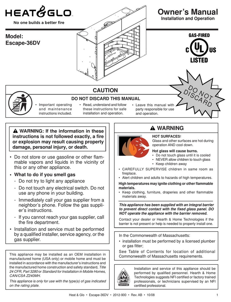
Heat & Glo Everest User manual

Heat & Glo

Heat & Glo Everest User manual

Heat & Glo SL-550TR-E User manual

Heat & Glo

Heat & Glo SL-550TR-E User manual

Heat & Glo COSMO-I30AU User manual

Heat & Glo

Heat & Glo COSMO-I30AU User manual
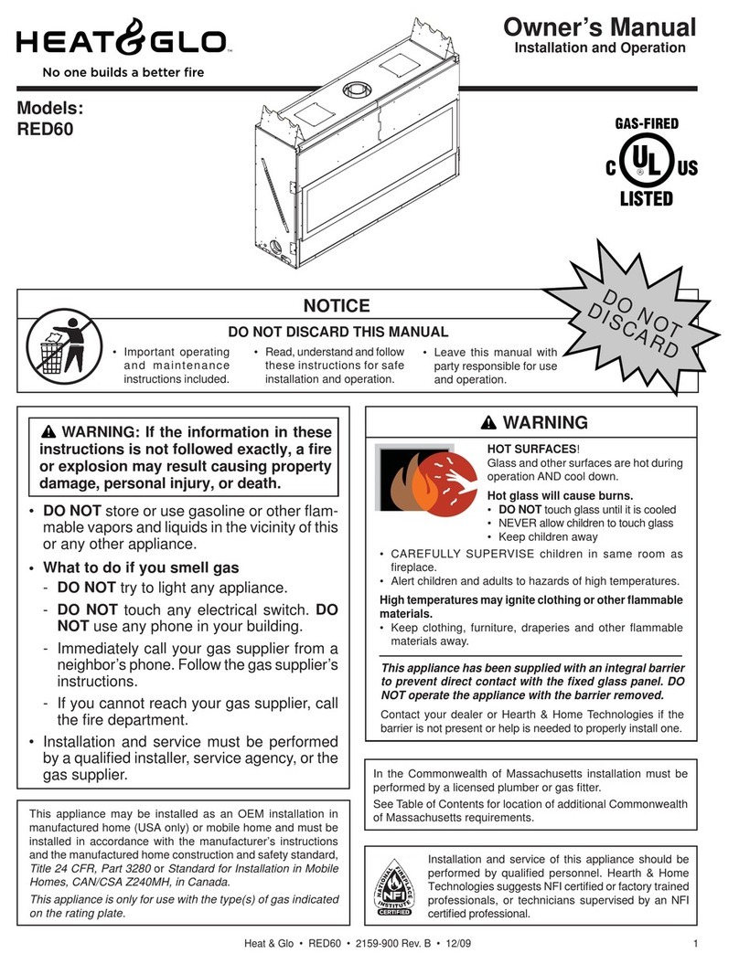
Heat & Glo SOHO-B-CEB User manual

Heat & Glo

Heat & Glo SOHO-B-CEB User manual

Heat & Glo Foundation Series User manual

Heat & Glo

Heat & Glo Foundation Series User manual

Heat & Glo Options User manual

Heat & Glo

Heat & Glo Options User manual

Heat & Glo LUX36 User manual

Heat & Glo

Heat & Glo LUX36 User manual

Heat & Glo PRIMO60 User manual

Heat & Glo

Heat & Glo PRIMO60 User manual

Heat & Glo TRUE-36C User manual

Heat & Glo

Heat & Glo TRUE-36C User manual

Heat & Glo Gas Fireplace SOULSTICE User manual

Heat & Glo

Heat & Glo Gas Fireplace SOULSTICE User manual

Heat & Glo ST-550T-IPI User manual

Heat & Glo

Heat & Glo ST-550T-IPI User manual

Heat & Glo VRTIKL User manual

Heat & Glo

Heat & Glo VRTIKL User manual

Heat & Glo TRUE-36S-IFT User manual

Heat & Glo

Heat & Glo TRUE-36S-IFT User manual

Heat & Glo 8000TV-OAK User manual

Heat & Glo

Heat & Glo 8000TV-OAK User manual

Heat & Glo SL-550TRS-E User manual

Heat & Glo

Heat & Glo SL-550TRS-E User manual

Heat & Glo ST-550TM-IPI User manual

Heat & Glo

Heat & Glo ST-550TM-IPI User manual

Heat & Glo MTL-INSERT User manual

Heat & Glo

Heat & Glo MTL-INSERT User manual

Heat & Glo EM-415 User manual

Heat & Glo

Heat & Glo EM-415 User manual

Heat & Glo Heat & Glo RED40 User manual

Heat & Glo

Heat & Glo Heat & Glo RED40 User manual

Heat & Glo SLR-C (COSMO) User manual

Heat & Glo

Heat & Glo SLR-C (COSMO) User manual

Heat & Glo I30X-N-AU User manual

Heat & Glo

Heat & Glo I30X-N-AU User manual

Heat & Glo COSMO-I30-IFT User manual

Heat & Glo

Heat & Glo COSMO-I30-IFT User manual

Heat & Glo ST-HVB-CE User manual

Heat & Glo

Heat & Glo ST-HVB-CE User manual

Heat & Glo NorthStar EPA Phase II User manual

Heat & Glo

Heat & Glo NorthStar EPA Phase II User manual

Popular Indoor Fireplace manuals by other brands

GLEN CANYON 4501138 instruction manual

GLEN CANYON

GLEN CANYON 4501138 instruction manual

Dru 105/2 RCH instruction manual

Dru

Dru 105/2 RCH instruction manual

TOOLCRAFT DJ209 operating instructions

TOOLCRAFT

TOOLCRAFT DJ209 operating instructions

Twin-Star International 18DM1141 Assembly instructions

Twin-Star International

Twin-Star International 18DM1141 Assembly instructions

Travis Industries 430 GSR2 installation instructions

Travis Industries

Travis Industries 430 GSR2 installation instructions

Twin-Star International Bell'O 42MM3115 manual

Twin-Star International

Twin-Star International Bell'O 42MM3115 manual

Twin-Star International 23MM378 manual

Twin-Star International

Twin-Star International 23MM378 manual

Escea EK1250 Installation instructions and user guide

Escea

Escea EK1250 Installation instructions and user guide

FAJARDO Ronda user guide

FAJARDO

FAJARDO Ronda user guide

Firegear Kalea Bay OFP-36LECO-NLED Installation and operating instructions

Firegear

Firegear Kalea Bay OFP-36LECO-NLED Installation and operating instructions

Napoleon NEFB27H Installation and operation manual

Napoleon

Napoleon NEFB27H Installation and operation manual

Lennox REFLECTIONS LSE-36R Installation and operation instructions

Lennox

Lennox REFLECTIONS LSE-36R Installation and operation instructions

Ameriwood HOME AtraFlame 1860096COM manual

Ameriwood HOME

Ameriwood HOME AtraFlame 1860096COM manual

Regency City CB60E-1 Owners & installation manual

Regency

Regency City CB60E-1 Owners & installation manual

NetZero Kalfire E-one 130F Installation and operation manual

NetZero

NetZero Kalfire E-one 130F Installation and operation manual

Regency Fireplace Products City Series ACV40ENG Owners & installation manual

Regency Fireplace Products

Regency Fireplace Products City Series ACV40ENG Owners & installation manual

Nordpeis Salzburg C installation manual

Nordpeis

Nordpeis Salzburg C installation manual

Monessen Hearth WDV Wideview WDV500 Installation and operating instructions

Monessen Hearth

Monessen Hearth WDV Wideview WDV500 Installation and operating instructions

manuals.online logo
manuals.online logoBrands
  • About & Mission
  • Contact us
  • Privacy Policy
  • Terms and Conditions

Copyright 2025 Manuals.Online. All Rights Reserved.