HEAT GLO GL-36D User manual
1
Heat & Glo • GL-36D, GL-42D, GL-36XD, GL-42XD Installation Instructions • 2506-931 Rev. D • 5/18
REQUIRED TOOLS
Screw gun equipped with 1/4 in (6 mm). socket or
1/4 in. (6 mm). wrench or socket
KIT COMPONENTS
(1) Rear Refractory Bracket
(1) Rear Insulation Board
(2) Side Glass Panels
(1) Rear Glass Panel
(1) Top Refractory Panel (GL-36XD / GL-42XD Kit Only)
(2) Side Refractory Bracket
(2) Side Insulation Board
(2) Base Refractory, Left and Right (CLX Models Only)
(1) Base Refractory, Center (CL Models Only)
(1) Glass Baffle (GL-36D / GL-42D Kit Only)
(5) Screws
Leave this manual with party responsible for use
and operation.
Installation Instructions
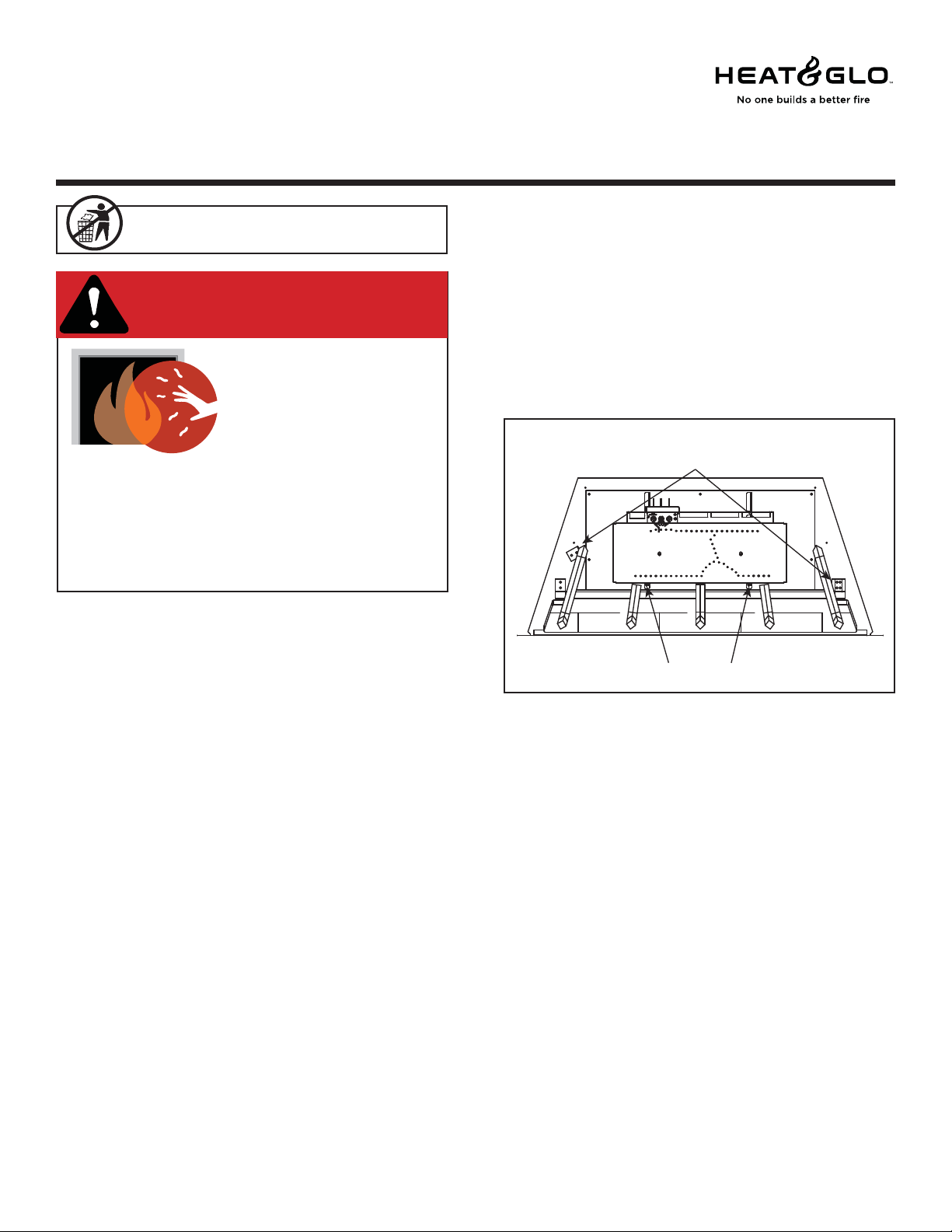
1. Remove decorative front and logs.
2. Remove existing refractory and discard.
6000C-IFT/8000C-IFT Only: Retain front base refrac-
tory.
3. Remove grate by removing one screw on each side.
See Figure 1.
CAUTION! Risk of Cuts or Abrasions. Wear protective
gloves and safety glasses during installation.
NOTICE: Handle refractory panels with care. Refractory
may chip or crack if dropped or impacted.
GLASS REFRACTORY KIT
GL-36D, GL-42D GL-36XD, GL-42XD
Models: 6000C-IPI/IFT, 6000CL-IPI/IFT, 6000CLX-IPI/IFT,
8000C-IPI/IFT, 8000CL-IPI/IFT, 8000CLX-IPI/IFT
Installation Instructions
CAUTION! Do not install damaged components.
DANGER
HOT GLASS WILL
CAUSE BURNS.
DO NOT TOUCH GLASS
UNTIL COOLED.
NEVER ALLOW CHILDREN
TO TOUCH GLASS.
A barrier designed to reduce the risk of
burns from the hot viewing glass is provided
with this appliance and shall be installed for
the protection of children and other at-risk
individuals.
Figure 1. Remove Grate
BURNER SCREWS
GRATE SCREWS
4. Remove the air scoop by removing the two screws
that attach it to the pilot cover. Remove the pilot cover
by removing the 2 screws. Unscrew the pilot from the
burner shield. Push the pilot towards the back of the
unit. Remove the fiber burner top by carefully lifting it
off the burner assembly. See Figure 2. Remove the
burner assembly by removing the 2 screws located
between the base refractory and the burner assembly.
See Figure 1. Slide the burner to the left and remove
the burner assembly.
CAUTION! Risk of Burns! Install this refractory only af-
ter the appliance has cooled and the gas and electricity
have been shut off.
2Heat & Glo • GL-36D, GL-42D, GL-36XD, GL-42XD Installation Instructions • 2506-931 Rev. D • 5/18
5. Remove media tray by removing two screws, one on
each side of tray. See Figure 3.
6000C-IFT/8000C-IFT Only: Remove four screws.
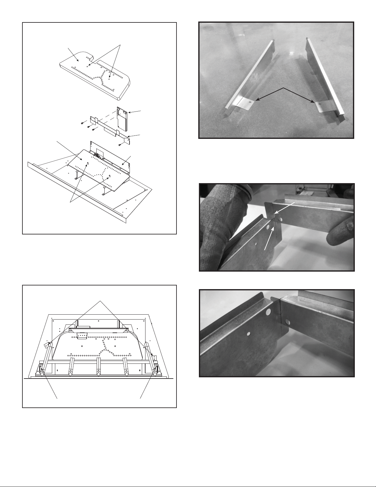
6. Locate the rear refractory bracket and side refractory
bracket pieces included in the kit.
7. Bend wings of side brackets as shown in Figure 4 prior
to attaching to rear refractory bracket.
Figure 5. Refractory Bracket Slot Locations
Figure 3
Figure 2
GUIDE SLEEVES
FIBER BURNER TOP
BURNER ASSEMBLY PILOT COVER
LOCATING HOLES
BURNER SHIELD
AIR SCOOP
GRATE SCREWS
MEDIA TRAY SCREWS
Figure 6. Side and Rear Refractory Brackets Connected
REAR SLOT
REAR SLOT
SIDE SLOT
SIDE SLOT
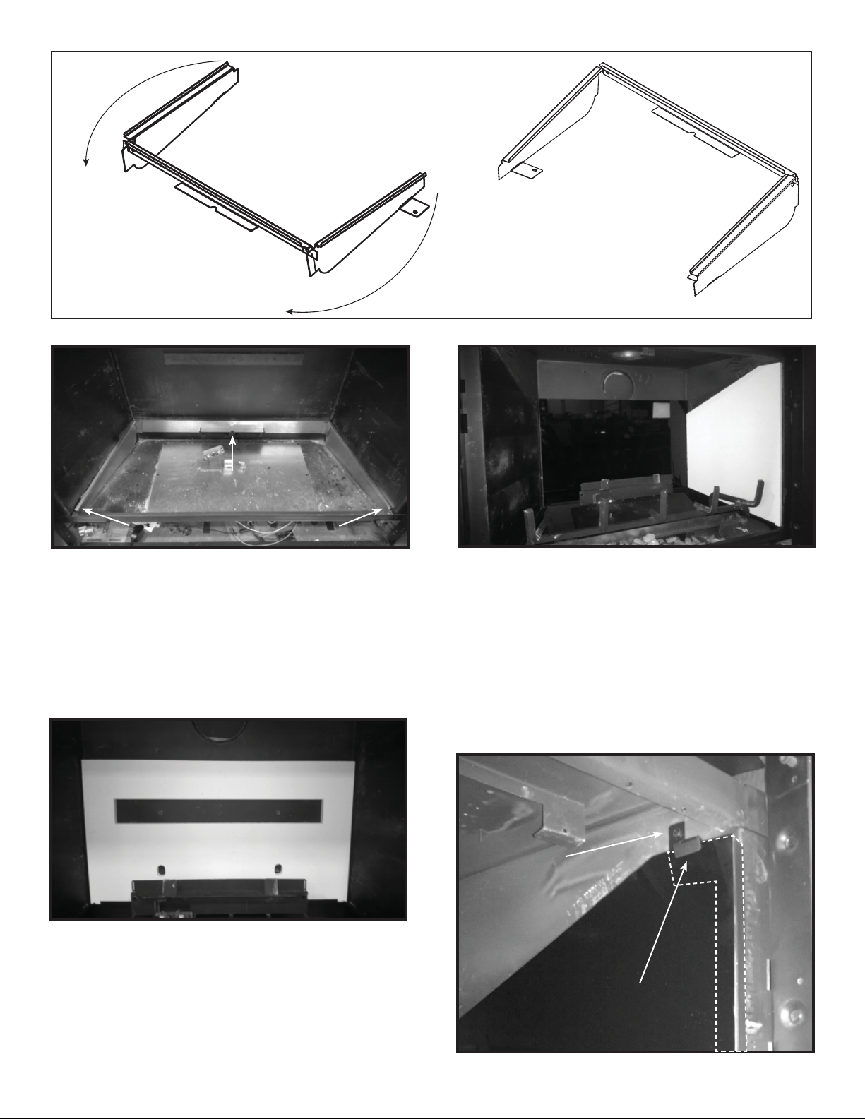
9. Bend the side pieces of the assembly around the rear
piece as shown in Figure 7.
10. Place the refractory bracket assembly into the firebox
by setting the front of the side brackets in position and
then resting the back of the side brackets in position
on the bottom of the appliance. Install one screw as
shown in Figure 8.
8. Connect the sides and rear bracket refractory pieces
by inserting each side piece into the slot on the rear
piece as shown in Figure 5 and Figure 6.
Figure 4. Bend Wings of Side Brackets
WINGS BENT
WINGS BENT
3
Heat & Glo • GL-36D, GL-42D, GL-36XD, GL-42XD Installation Instructions • 2506-931 Rev. D • 5/18
Figure 7. Refractory Bracket Assembled
11. Reinstall media tray, burner, burner overlay and grate.
Media tray will be installed over the top of the side
bracket wings.
12. Install rear insulation board by positioning it at the
rear of the firebox and on the rear refractory bracket
as shown in Figure 9.
Figure 8. Refractory Bracket Assembly Installed
PLACE FRONT OF
PLACE FRONT OF
SIDE BRACKETS FIRST
SIDE BRACKETS FIRST
SCREW
SCREW
Figure 9. Install Rear Insulation Board
Figure 10. Install Rear Glass Panel and Right Side Insulation
Board
13. Install rear glass panel in front of insulation board on
rear refractory bracket. Hold rear glass panel in place
and slide one side insulation board into position be-
tween side refractory bracket and side of firebox as
shown in Figure 10. Figure 11. Install Side Glass Retention Bracket
14. Install side glass panel in front of insulation board.
15. Install side refractory bracket between the insulation
board and the side of the firebox. Secure with screw
as shown in Figure 11.
16. Bend side refractory tab over glass panel. See Fig-
ure 11.
17. Install side insulation board on opposite side and re-
peat steps 14-16 for other side.
SCREW
SCREW
TAB BENT OVER SIDE
TAB BENT OVER SIDE
GLASS PANEL
GLASS PANEL
BEND REFRACTORY BRACKET
SIDES OUT AND AROUND
REFRACTORY BRACKET
READY TO INSTALL

4Heat & Glo • GL-36D, GL-42D, GL-36XD, GL-42XD Installation Instructions • 2506-931 Rev. D • 5/18
20. (GL-36D / GL-42D Only)
The optional refractory kit requires a larger glass baf-
fle which is sent with the refractory set. To remove the
old glass baffle, remove the screw located on top of
firebox and discard the glass baffle. See Figure 15.
21. Install new glass baffle by aligning the three screw
tips with the three clearance holes shown in Figure
16. Attach screw as shown.
Figure 15. Remove Glass Baffle - GL-36D / GL42D Only
SCREW PASSES DOWN THROUGH FIREBOX TOP
AND INTO GLASS BAFFLE
GLASS BAFFLE SCREW
GLASS BAFFLE
Figure 13. Install Base Refractory - CLX Models
BASE REFRACTORY
BASE REFRACTORY
Figure 14. Install Base Refractory - C and CL Models
Figure 12. Install Top Refractory Panel (GL-36XD / GL-42XD Only)
19. Set new base refractory piece(s) in place as shown in
Figure 13 (CLX) and Figure 14 (CL).
18. GL-36XD / GL-42XD Kit Only: Install top refractory
panel. Rest it on top of the side glass panels and
gently push to the rear. See Figure 12.

5
Heat & Glo • GL-36D, GL-42D, GL-36XD, GL-42XD Installation Instructions • 2506-931 Rev. D • 5/18
Please contact your Heat & Glo
dealer with any questions or concerns.
For the location of your nearest
Heat & Glo dealer,
please visit www.heatnglo.com.
Hearth & Home Technologies
7571 215th Street West, Lakeville, MN 55044
www.heatnglo.com
NEW GLASS BAFFLE
CLEARANCE HOLES
SCREW TIPS
NEW GLASS BAFFLE INSTALLED
Figure 16. Install New Glass Baffle - GL-36D / GL42D Only
23. Reinstall logs using log placement instructions in
appliance installation manual. Reinstall decorative
front.
22. (6000CL-IPI/8000CL-IPI/6000CLX-IPI/8000CLX-IPI
Only)
Disconnect the rear ember lights as shown in Figure
17.
LED
CONTROL
FRONT EMBER LIGHTING (X 3)
DISCONNECT REAR ACCENT LIGHTING (X 2)
Figure 17. Disconnect Rear Accent Lights
This manual suits for next models
14
Popular Fireplace Accessories manuals by other brands


Snow Peak
Snow Peak ST-034BP instruction manual

Napoleon
Napoleon PRP45 installation instructions

Remington
Remington REM-L240BNO-V User's manual and operating instructions

Dimplex
Dimplex SOP-295-E install guide

Valcourt
Valcourt AC04312 installation instructions

Fires of Tradition
Fires of Tradition Octavia Install instructions

EcoSmart Fire
EcoSmart Fire Curved CLEARANCES & INSTALLATION

Valor
Valor H6 Series installation instructions

HearthStone
HearthStone 90-99099 owner's manual

Wolf Steel
Wolf Steel DBPEX36 installation instructions

Empire Comfort Systems
Empire Comfort Systems DCA1ABL-1 quick guide

HearthStone
HearthStone Montgomery 94-5110010 installation guide