Heat Seal 625ES Guide

Revised 2017
READ ALL INSTRUCTIONS CAREFULLY BEFORE OPERATING EQUIPMENT
OPERATING & SERVICE PARTS MANUAL
625ES ENERGY SMART WRAPPER

2
Revised 2017
TABLE OF CONTENTS
Machine Components & Electrical Requirements ......................................................3
Preliminary Setup..........................................................................................................5
Recommended Maintenance ........................................................................................6
Troubleshooting Guide .................................................................................................7
Hot Rod Circuit Board Test...........................................................................................9
Replacing Rocker Arm Assembly...............................................................................10
Service Parts Information ........................................................................................... 11
3
Revised 2017
MACHINE TECHNOLOGY & COMPONENTS
HOT ROD HEAT UP
With the film properly mounted and threaded, the wrapper is ready to be powered up. See INSTALLING & REPLACING
AXLE ASSEMBLY.
After plugging the power cord into an electrical outlet, flip the power switch located on the back of the electrical box to the
ON position.
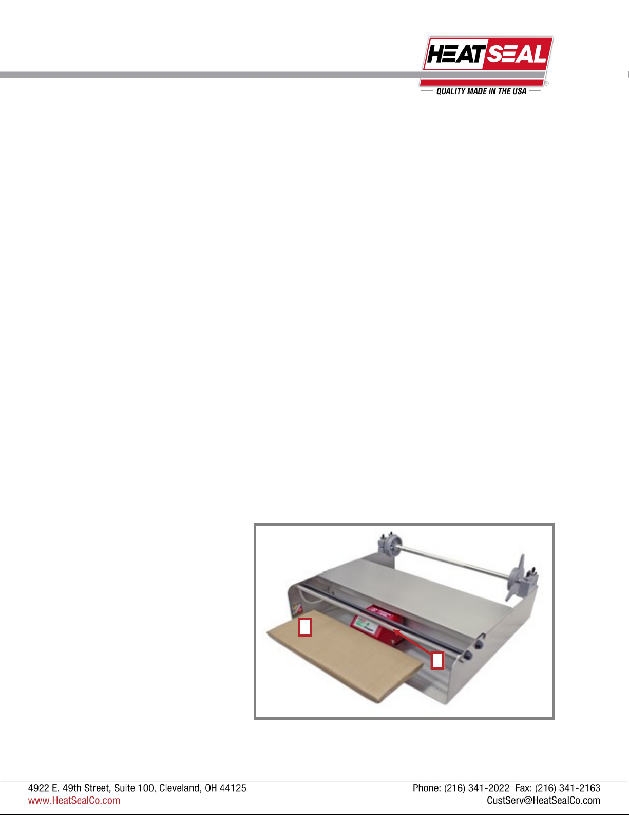
The hot rod (1) will require about a 5 minute warm up period before it reaches a cutting temperature of above 275˚ F.
CAUTION: As long as the wrapper is powered on, the rod will be hot and skin contact should be avoided.
LOAD ACTIVATED HEATER
The seal plate of the wrapper is activated by a switch that is engaged when a downward load is applied to the plate (2).
This feature ensures that the seal plate will consume energy only when there is a demand by the operator.
Do NOT use the seal plate as a cutting surface, as this will damage the thin heating foil and Non-stick cover plate. Seal
plate damage voids the warranty.
ENERGY SMART TECHNOLOGY
The Energy Smart Wrapper is an innovative system that incorporates an “Instant On” heating foil with the ability to go
from ambient to sealing temperature in a matter of seconds. The high speed foil in combination with a load activated
switch allows the operator to seal a product on demand and to save energy when the wrapper is not in use. The first step
to getting the wrapper up and running is to set up the axle assembly and get the film mounted and threaded properly.
The special heating foil has been tested as part of our quality procedures and you may see a wavy or wrinkling affect on
the surface of the stainless steel plate just under the replaceable Non-stick cover. This waviness is caused by the differ-
ential thermal expansion of the materials that are used to construct the layered seal plate and wrinkling will be observed
as the wrapper is used daily and the seal plate settles in.
1
2
ELECTRICAL
REQUIREMENTS
The Model 625ES requires 115 volts,
16 amps.
(20A breaker required)
4
Revised 2017
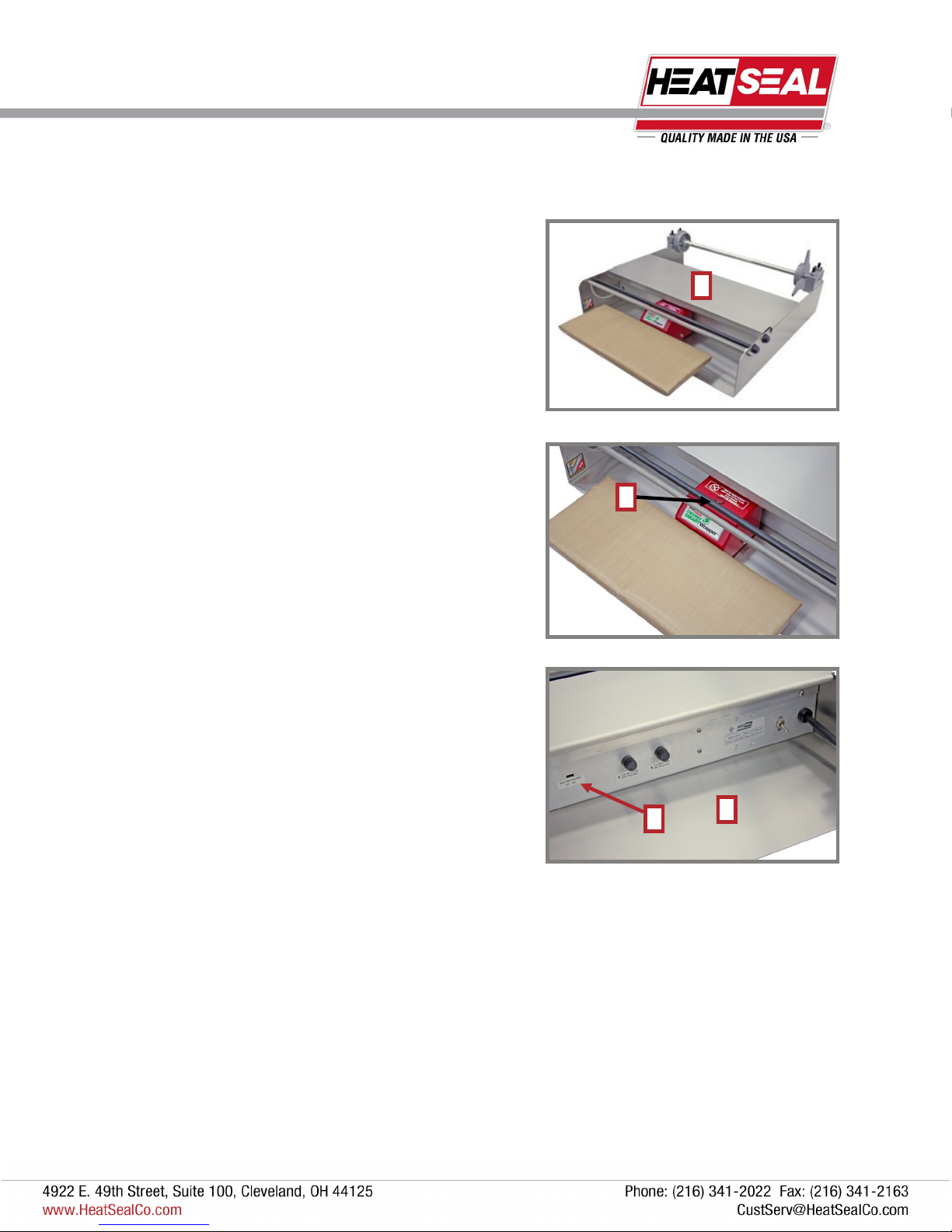
STAINLESS STEEL BRIDGE
The wrapper comes with a stainless steel bridge (1) that can be
utilized as a working surface while preparing products.
The stainless steel bridge is not recommended as a cutting
surface.
OPERATOR INDICATOR LIGHT
Since the sealing plate is only activated when a load is applied,
a red neon light (2) has been included to provide the operator a
visual indicator that the heater is active. When the light is on, the
seal plate switch is engaged and its surface will become hot
Instantly.
TWO POSITION SWITCH
On the back of the electrical box, there is a two position switch
(3) which allows the operator to vary the length of time that the
seal plate is on. The 3.0 and 4.0 second settings allow for differ-
ent film types being used. The 3.0 setting should be used to seal
most film types. However, you should test the seal ability of your
specific film material. The red neon light gives the operator a
visual time reference to these settings when sealing a product.
In order to maximize the energy savings of the wrapper, it is
suggested to use the lowest possible time setting that yields a
proper seal using the specific film selected for wrapping.
GFCI
Effective on machines produced after June 2015 (Serial # past
1506XXXXX), to maintain circuit protection and integrity, a GFCI
(4) is installed in the electrical box, and may need to be reset if
wrapper gets wet or other ground faults arise. Do NOT reset the
GFCI, if visible seal plate damage is present.
THERMISTOR TEMPERATURE CONTROL
Due to the rapid response of the heating foil and residual heat that can remain from previous cycles, a thermistor is incorpo-
rated as a temperature control device. The seal cycle can be shorter than 3 seconds when residual heat is present in seal
plate. The thermistor is located on the heating foil and it regulates the temperature of the seal plate to ensure that the foil
temperature peaks at around 300˚F.
NOTE: The thermistor is the governing control to supply heat to the seal plate over the timed indicator light. Therefore, if
residual heat is present in the seal plate, the sealing cycle can be shorter than the timed neon light. You should hear a brief
click when the foil reaches sealing temperature.
1
2
3
MACHINE TECHNOLOGY & COMPONENTS
4
5
Revised 2017
PRELIMINARY SETUP
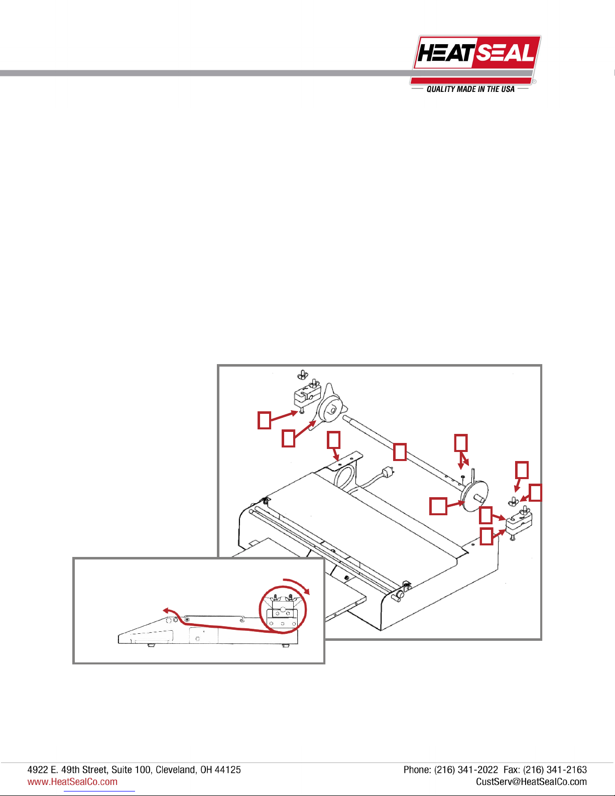
INSTALLING & REPLACING AXLE ASSEMBLY
To install the axle assembly (1), simply position the assembly at the rear of the machine with the removable end cap (2) on
the left side as pictured below.
Insert two bolts (3) on each side through the holes in the machine base (4) and bearing blocks (5), screw on wing nuts (6)
and luster caps (7) to the ends of the screws
To replace the axle, remove cap (7) from end of one bolt and unscrew wing nut (6), then swing top bearing block away (8) to
release the axle assembly, unscrew removable cap (2), and replace film roll.
ADJUSTING FOR DIFFERENT WIDTH FILMS
Loosen the wing nuts and swing out upper bearing blocks on both sides.
Lift out the axle assembly, unscrew the movable end cap and position the fixed cap for film size being used and secure with
pin and o-ring (9).
Place the core of the film against the fixed cap (10), screw removable cap (2) in to film roll core and feed film from bottom of
roll (see film threading diagram below).
9
4
7
3
1
10
6
2
5
8
FILM THREADING DIAGRAM
Table of contents
Other Heat Seal Food Saver manuals


