Heat Seal 625A MINI Guide
Revised 2013
READ ALL INSTRUCTIONS CAREFULLY BEFORE OPERATING EQUIPMENT
OPERATING & SERVICE PARTS MANUAL
TABLE TOP OVERWRAPPERS
AXLE MOUNT MODELS:
MODEL 625A
SINGLE ROLL WITH MOUNTING AXLES
MODEL 625A MINI
COMPACT SINGLE ROLL WITH MOUNTING AXLES
MODEL 825A
DUAL ROLL WITH MOUNTING AXLES
MODEL 875A
TRIPLE ROLL WITH MOUNTING AXLES
FILM ROLLER MODELS:
MODEL 600A
SINGLE ROLL WITH ROLLERS
MODEL 500A
COMPACT SINGLE ROLL WITH ROLLERS
MODEL 500A MINI
COMPACT SINGLE ROLL WITH ROLLERS
MODEL 800A
DUAL ROLL WITH ROLLERS
MODEL 850A
TRIPLE ROLL WITH ROLLERS
Model 625A
Model 600A
Model 825A

2
Revised 2013
TABLE OF CONTENTS
Film Threading...............................................................................................................3
Installing the Film Axle..................................................................................................4
625A Schematic & Parts List ........................................................................................5
625A Mini Schematic & Parts List ................................................................................6
825/875A Schematic & Parts List .................................................................................7
600A Schematic & Parts List ........................................................................................8
800/850A Schematic & Parts List .................................................................................9
Electrical Service Information ....................................................................................10
Electrical Schematics.................................................................................................. 11
Electrical Box & Hot Plate Schematic & Parts List ...................................................12

3
Revised 2013
FILM THREADING
FOR AXLE TYPE WRAPPERS (625, 825, 875):
See instructions on next pages to load the film onto the axle.
Thread the film as shown, one at a time or as needed.
FOR ROLLER TYPE WRAPPERS (600, 800, 850):
Rest film Roll on top of two rollers, centering film between the film guides. Tighten the thumbscrew against the film brake to
ensure proper film tension. Thread the film as shown, threading one at a time or as needed.

4
Revised 2013
INSTALLING & ADJUSTING THE FILM AXLE
INSTALLING COMPLETE AXLE ASSEMBLY (625-A)
Position the complete axle assembly on the rear of the
wrapper with the removable end cap (1) on the left side and
the bearing blocks (2) on the outside of the sides of the
machine base (3) as shown in the drawing.
Fasten the bearing blocks to the sides of the machine base
with the four bolts (4), lock washers (5) and hex nuts (6)
provided in the bearing block set.
INSTALLING COMPLETE AXLE ASSEMBLY (825-A/875-A)
Position the complete axle assemblies between the side
plates of the wrapper with the removable end cap on the
left side and the bearing blocks and mounting brackets on
the inside of the plates.
Fasten bearing blocks, mounting bracket and axle to the
side plates with the fasteners provided in the bearing block
set
REMOVING THE AXLE
Remove the protective caps from the ends of both bolts
located in the slotted holes of the upper bearing blocks (7).
Remove the wing nuts on both bolts with the protective
caps removed and loosen the wing nuts on both bolts lo-
cated in the other holes of the upper bearing blocks.
Swing the upper bearing blocks toward the outside of the
machine base until the ends of the axle (8) are exposed.
Lift the axle out of the lower bearing blocks (9).
INSTALLING THE AXLE
Place the ends of axle into the grooves on lower bearing
blocks with the removable end cap positioned on the left
side as shown in the illustration.
Swing the upper bearing blocks toward the inside of the
machine base until they align with the lower bearing blocks.
Thread the wing nuts onto both of the bolts located in the
slotted holes of the upper bearing blocks and tighten all of
the wing nuts on all four of the bolts in the bearing block
assemblies.
Replace the protective caps on the ends of both bolts lo-
cated in the slotted holes of the upper bearing blocks.
CHANGING THE AXLE END CAP WIDTH
Pull pin (10) out of the outer flange of hub (11) until the end
of pin clears the inner flange of hub. Do not completely
remove the pin from the hub.
Slide the hub to the new position and align the hole on the
inner flange on hub with the nearest hole in the axle.
Push the pin completely through the inner flange of hub and
the axle until the top of the pin is flush with the outer flange
of hub.
5
Revised 2013
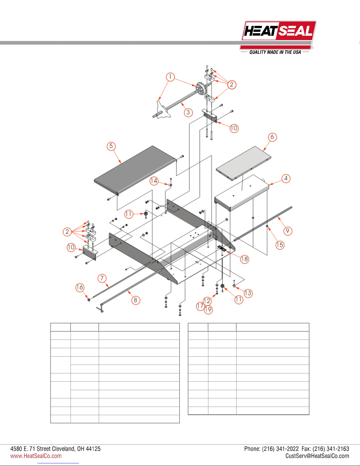
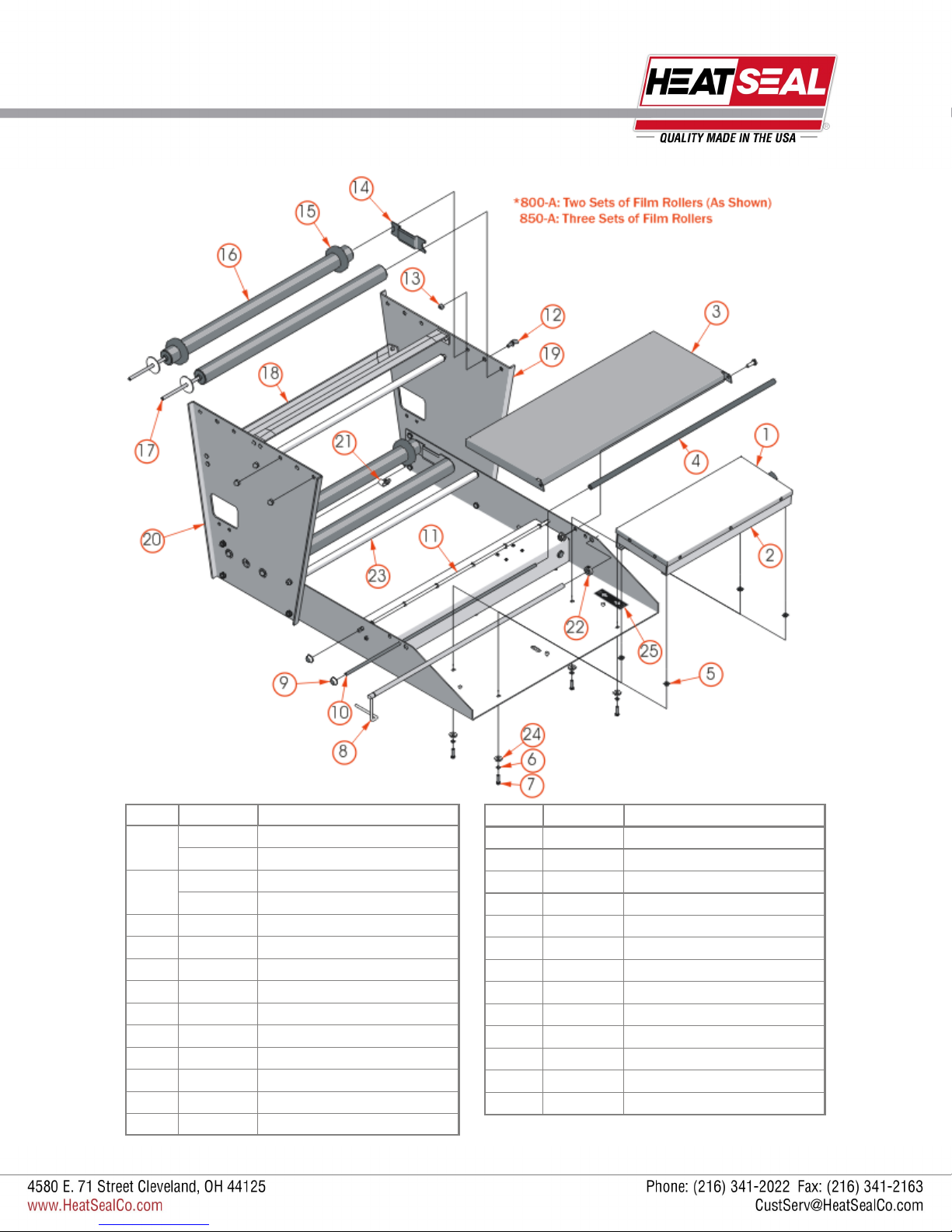
MODEL 625A REPLACEMENT PARTS
ITEM PART # DESCRIPTION
1 6110-023 Film Core Adapter Set
2 6305-018 Bearing Block Set
3 3005-004 Film Core Axle, 21 15/16” L
4 6101-020 Hot Plate Assy, 6 by 15
6102-043 Hot Plate Assy, 8 by 15
5 6102-052 Wrapping Bridge
6 5901-011 Non-stick Cover, 6 by 15
5901-001 Non-stick Cover, 8 by 15
7 6301-019 Film Retainer Rod
8 1824-011 Cut-Off Rod, 23” L
9 6301-018 Vinyl Film Retainer
ITEM PART # DESCRIPTION
10 6305-048 Bearing Block Support Bracket
11 2135-001 Large Rubber Foot
12 1903-188 Hex Head Cap Screw
13 3005-010 Cut-Off Rod Collar
14 1927-008 Vinyl Clamp
15 1833-002 Fiber Insulator Washer
16 1958-001 Metal Shaft Retainer
17 1907-005 Lock Washer
18 2150-232 Hi-Lo Decal
19 1909-019 No. 10 Flat Washer
6
Revised 2013
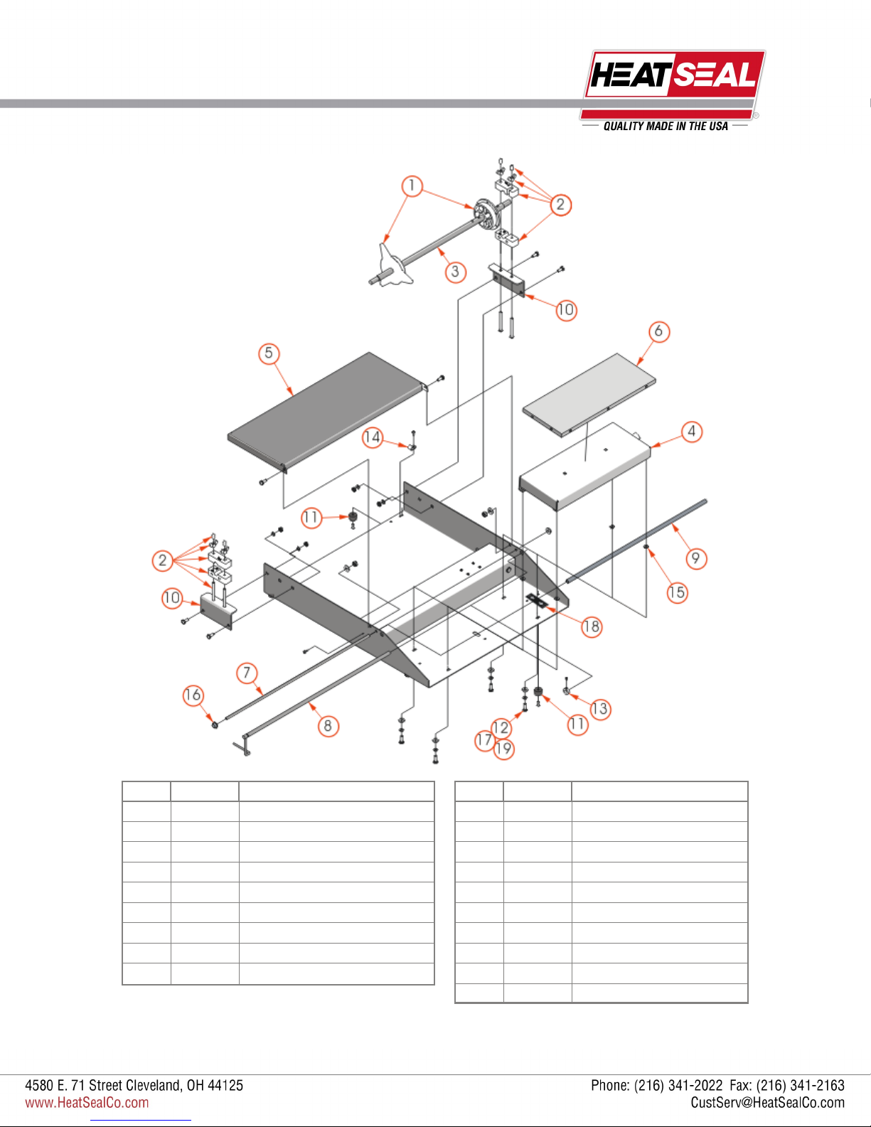
MODEL 625A MINI REPLACEMENT PARTS
ITEM PART # DESCRIPTION
1 6110-023 Film Core Adapter Set
2 6305-018 Bearing Block Set
3 3005-006 Film Core Axle, 16 7/8” L
4 6305-132 Hot Plate Assy, 6 by 9
5 6305-050 Wrapping Bridge
6 5901-014 Non-stick Cover, 6 by 9
7 6305-049 Film Retainer Rod
8 1824-010 Cut-Off Rod, 15 1/2” L
9 6305-120 Vinyl Film Retainer
ITEM PART # DESCRIPTION
10 6305-048 Bearing Block Support Bracket
11 2135-001 Large Rubber Foot
12 1903-188 Hex Head Cap Screw
13 3005-010 Cut-Off Rod Collar
14 1927-008 Vinyl Clamp
15 1833-002 Fiber Insulator Washer
16 1958-001 Metal Shaft Retainer
17 1907-005 Lock Washer
18 2150-232 Hi-Lo Decal
19 1909-019 No. 10 Flat Washer

7
Revised 2013
MODEL 825A/875A REPLACEMENT PARTS
ITEM PART # DESCRIPTION
1 5901-011 Non-stick Cover, 6 by 15
5901-001 Non-stick Cover, 8 by 15
6101-020 Hot Plate Assy, 6 by 15
2 6102-043 Hot Plate Assy, 8 by 15
3 6102-052 Wrapping Bridge
4 6301-018 Film Guide Tube
5 1833-002 Fiber Insulator Washer
6 1907-005 Lock Washer
7 1903-188 Hex Head Cap Screw
8 1824-011 Cut-Off Hot Rod, 23” L
9 1958-001 Shaft Retainer
10 6310-043 Film Guide Shaft 22 3/4” L
11 6301-035 Film Guide Shaft 22 3/4” L
ITEM PART # DESCRIPTION
12 6305-075 Bearing Block Set
13 3005-004 Film Core Axle, 21 15/16”L
14 6310-046 Right Hand Side Plate
15 6310-047 Left Hand Side Plate
16 6310-041 Support Bracket
17 1927-008 Vinyl Clamp
18 6301-037 Film Separator Roller
19 3005-010 Cut-Off Rod Collar
20 6110-023 Film Core Adapter Kit
21 2150-232 Hi-Lo Decal
22 1909-019 No. 10 Flat Washer
23 6305-048 Bearing Block Support Bracket
24 6310-045 Bearing Block Support Bracket

8
Revised 2013
MODEL 600A REPLACEMENT PARTS
ITEM PART # DESCRIPTION
1 6301-017 Film Roller Assembly
2 6301-018 Vinyl Film Retainer
3 6301-019 Film Retainer Rod
4 1958-001 Metal Shaft Retainer
5 6101-020 Hot Plate Assy, 6 By 15
6102-043 Hot Plate Assy, 8 By 15
6 6102-052 Wrapping Bridge
7 5901-011 Non-stick Cover, 6 By 15
5901-001 Non-stick Cover, 8 By 15
8 3005-010 Cut-off Rod Collar
9 1903-188 Hex Head Cap Screw
10 1907-005 Lock Washer
ITEM PART # DESCRIPTION
11 1927-008 Vinyl Wire Clamp
12 1911-038 Clinch Nut
13 1923-002 Thumb Screw
14 1824-011 Cut-off Rod, 23” L
15 3010-021 Film Retainer/Guide, 1 3/8 Dia.
16 6301-020 Film Roller Brake
17 1911-001 Acorn Nut
18 1833-002 Fiber Insulator Washer
19 3005-036 Film Roller Shaft
20 1909-019 No. 10 Flat Washer
21 2150-232 Hi-Lo Decal
22 2135-001 Large Rubber Feet

9
Revised 2013
MODEL 500A REPLACEMENT PARTS
ITEM PART # DESCRIPTION
1 5901-011 Non-stick Cover, 6 By 15
2 6101-020 Hot Plate Assy, 6 By 15
3 1833-002 Fiber Insulator Washer
4 2150-232 Hot Plate Temp Control Decal
5 1909-019 No. 10 Flat Washer
6 1907-005 Lock Washer
7 1903-188 Hex Head Cap Screw
8 1824-011 Cut-off Rod, 23” L
9 3005-010 Cut-off Rod Collar
ITEM PART # DESCRIPTION
10 6301-018 Vinyl Film Retainer
11 6102-052 Wrapping Bridge
12 6301-020 Film Roller Brake
13 1909-003 Fender Washer
14 6301-017 Film Roller Assembly
15 3005-036 Film Roller Shaft ***
16 1958-001 Metal Shaft Retainer
17 2135-001 Large Rubber Feet
18 1927-008 Vinyl Wire Clamp
10
Revised 2013
MODEL 500A MINI REPLACEMENT PARTS
ITEM PART # DESCRIPTION
1 5901-014 Non-stick Cover, 6 By 9
2 6305-132 Hot Plate Assy, 6 By 9
3 1833-002 Fiber Insulator Washer
4 2150-232 Hot Plate Temp Control Decal
5 1909-019 No. 10 Flat Washer
6 1907-005 Lock Washer
7 1903-188 Hex Head Cap Screw
8 1824-010 Cut-Off Rod, 15 1/2” L
9 3005-010 Cut-off Rod Collar
ITEM PART # DESCRIPTION
10 6305-120 Vinyl Film Retainer
11 6305-065 Wrapping Bridge
12 6301-020 Film Roller Brake
13 1909-003 Fender Washer
14 6305-122 Film Roller Assembly
15 6305-121 Film Roller Shaft
16 1958-001 Metal Shaft Retainer
17 2135-001 Large Rubber Feet
18 1927-008 Vinyl Wire Clamp
11
Revised 2013
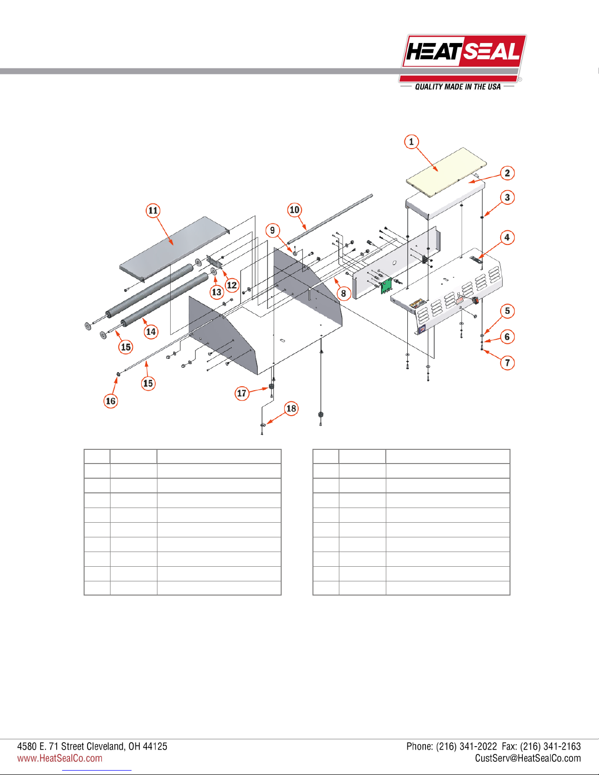
MODEL 800A/850A REPLACEMENT PARTS
ITEM PART # DESCRIPTION
5901-011 Non-stick Cover, 6 by 15
1 5901-001 Non-stick Cover, 8 by 15
2 6101-020 Hot Plate Assy, 6 by 15
6102-043 Hot Plate Assy, 8 by 15
3 6102-052 Wrapping Bridge
4 6301-018 Film Guide Tube
5 1833-002 Fiber Insulator Washer
6 1907-005 Lock Washer
7 1903-188 Hex Head Cap Screw
8 1824-011 Cut-Off Hot Rod 23” L
9 1958-001 Metal Shaft Retainer
10 6310-043 Film Guide Shaft, 22 3/4”
11 6301-035 Film Guide Shaft, 22 3/4”
12 1923-002 Thumb Screw
ITEM PART # DESCRIPTION
13 1911-038 Clinch Nut
14 6301-020 Film Tension Brake
15 3010-021 Film Retainer
16 6301-017 Film Roller Assembly
17 3005-036 Film Roller Shaft
18 6310-041 Support Bracket
19 6310-046 Right Hand Side Plate
20 6310-047 Left Hand Side Plate
21 1927-008 Vinyl Clamp
22 3005-010 Cut-Off Rod Collar
23 6301-037 Film Separator Roller
24 1909-019 #10 Flat Washer
25 2150-232 Hi-Lo Decal
12
Revised 2013
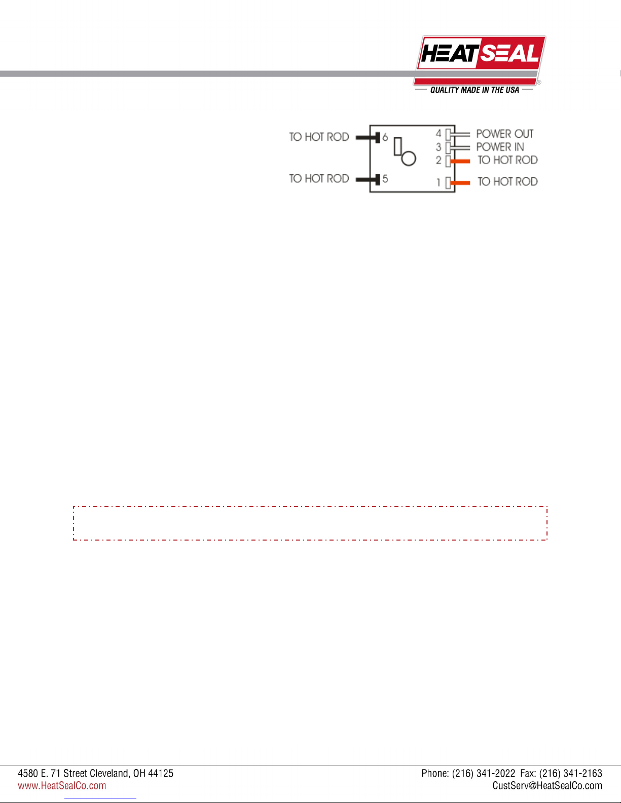
ELECTRICAL SERVICE INFORMATION
HOT ROD CIRCUIT BOARD TEST
A standard 115 volt neon circuit tester can be used for these tests.
CHECKING FUSES
Remove the fuse from their housing units located on the front of the electrical box. If a visual inspection does not verify a blown
fuse check for continuity by using the meter to read across the two terminals of the fuse.
If the meter reading does not show continuity, replace the fuse.
CHECKING THE HOT ROD
With the power turned OFF, remove the red hot rod wires from Terminals 1 and 2. Using the meter, measure the resistance of
the rod by connecting the leads of the meter to the red wires.
The meter should read between 130-136 ohms. If the reading is out of this range, replace the hot rod.
CHECKING THE CIRCUIT BOARD
After the hot rod and both the fuses have passed the above testing procedures, the circuit board can be tested.
With all the wires shown in the example circuit board (above) properly connected and the power ON, use the meter to test the
voltage across Terminals 1 and 2. If there is no voltage being read, the board needs to be replaced.
ELECTRICAL REQUIREMENTS
All Models are 110 Volts, 10 Amps.
THIS UNIT SHOULD NOT BE OPERATED IF ROD TEMPERATURE EXCEEDS
300 DEGREES FAHRENHEIT. IF SMOKE OR FUMES ARE DETECTED, DISCONTINUE USE

13
Revised 2013
ELECTRICAL DIAGRAMS
ITEM PART # DESCRIPTION
1 1821-013 Fuse Holder
2 1821-034 Fuse
3 1875-002 Terminal Block
4 1851-052 Power Cord
1872-008 Toggle Switch (Series A)
5 1872-009 Rocker Switch for 500 Series
6 1836-004 Pilot Light
7 1824-011 Cut-Off Hot Rod, 23” L
8 6110-016 Element
9 1818-001 Circuit Board
10 1881-002 Thermostat
11 1884-023 Timer (Series B)
14
Revised 2013
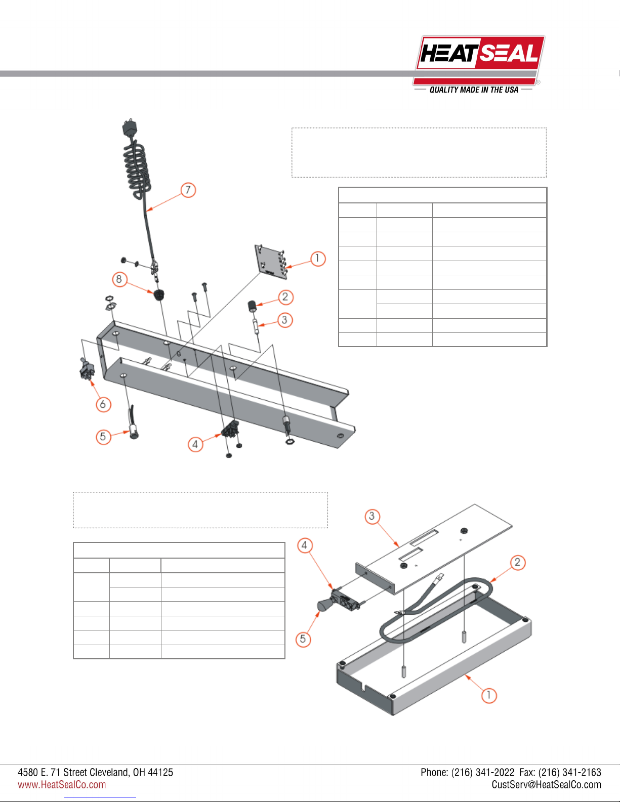
ELECTRICAL BOX & HOT PLATE PARTS
HOT PLATE REPLACEMENT PARTS
ITEM PART # DESCRIPTION
1 6305-076 Hot Plate, 6 by 15
6305-079 Hot Plate, 8 by 15
2 6110-016 Element
3 6305-080 Element Support Plate
4 1881-002 B-200 Thermostat
5 2145-023 Knob
ELECTRICAL BOX REPLACEMENT PARTS
ITEM PART # DESCRIPTION
1 1818-001 Circuit Board
2 1821-013 Fuse Holder
3 1821-034 Fuse, 1 A MDA Slo-Blo
4 1875-002 Terminal Block
5 1836-004 Pilot Light, Red
1872-008 Toggle Switch
6 1872-009 Rocker Switch (500 Series)
7 1851-052 Power Cord, 5 Ft.
8 1869-003 Strain Relief
TO SERVICE ELECTRICAL PARTS ON ELECTRICAL BOX:
Lift up the wrapping bridge, then remove the screws holding the
electrical control housing to the base. Lift out and replace parts.
TO SERVICE ELECTRICAL PARTS ON HOT PLATE:
Remove from wrapper base and replace worn or defective parts.
Standard Size Unit Shown
This manual suits for next models
8
Table of contents
Other Heat Seal Food Saver manuals


