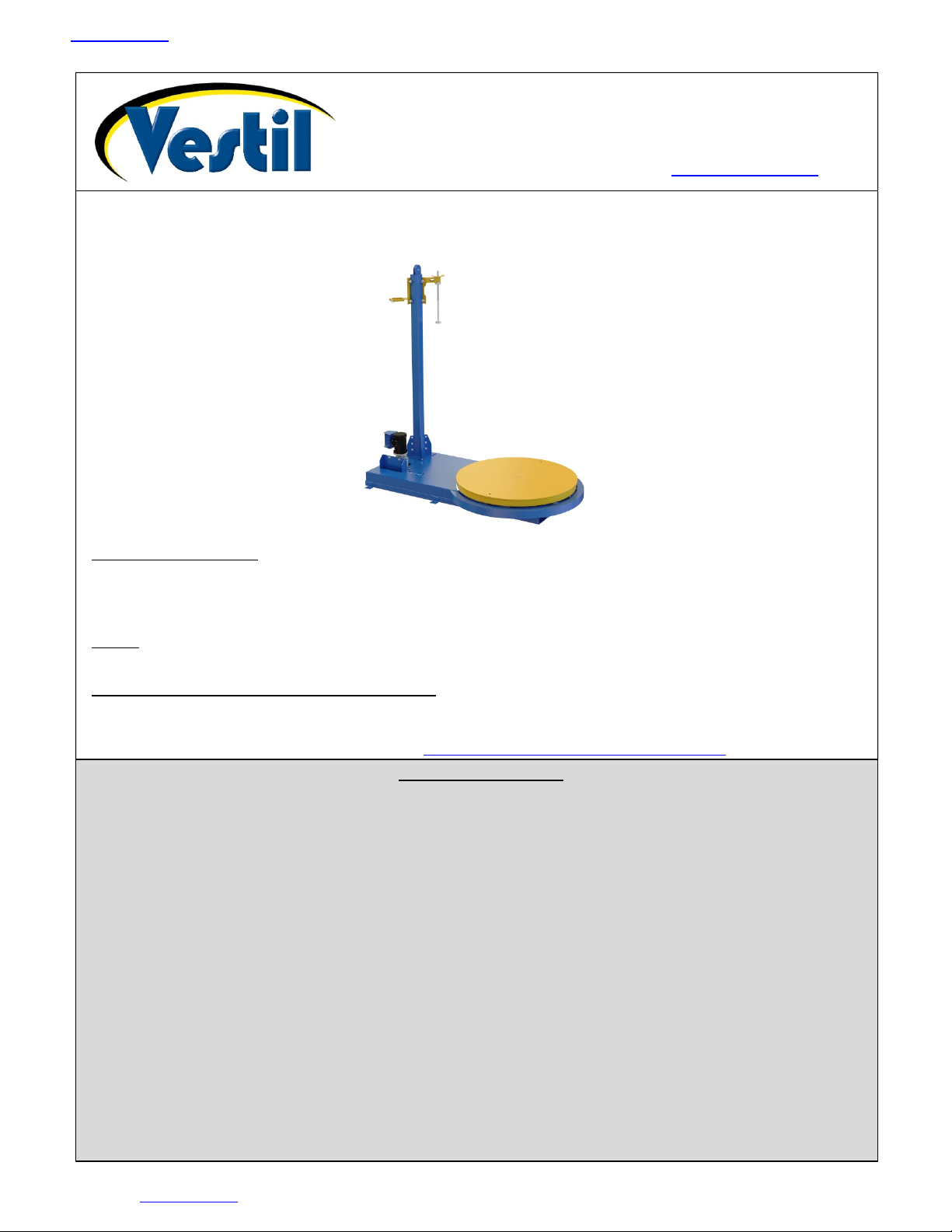
Table of Contents Rev. 4/23/2019 SWA-54 MANUAL
Table of Contents Copyright 2018 Vestil Manufacturing Corp. Page 3 of 17
Signal Words
This manual uses SIGNAL WORDS to identify hazards that could occur while using this product.
DANGER, WARNING, and CAUTION draw attention to hazards likely to cause personal injuries. Each
signal word implies a specific level of injury. NOTICE is used to indicate hazards likely to result in
property damage. The following are definitions for each word:
Identifies a hazardous situation which, if not avoided, WILL result in DEATH or
SERIOUS INJURY. Use of this signal word is limited to the most extreme situations.
Identifies a hazardous situation which, if not avoided, COULD result in DEATH or
SERIOUS INJURY.
Indicates a hazardous situation which, if not avoided, COULD result in MINOR or
MODERATE injury.
Identifies practices likely to result in product/property damage, such as operation that
might damage the product.
Hazards of Improper Use
We strive to identify all hazards that could occur while using our products, but no manual can address every risk.
The most effective way to avoid injury is to exercise sound judgment whenever using this device and to read the
entire manual carefully before installing, using, or servicing the product. Vestil recommends that you contact its
Technical Service Department (the “TSD”) if you have any questions about instructions in the manual. We intend to
provide our customers with the best instructions possible and encourage you to contact the TSD if you believe that a
necessary instruction is missing or incomplete.
Failure to read and understand the entire manual before assembling, installing, using and
servicing the product is a misuse of the product.If this product is used improperly or carelessly, the operator
and/or bystanders might sustain serious personal injuries. To reduce the likelihood of injury:
•DO NOT modify the product in any way UNLESS you first obtain written approval from Vestil. Unapproved
modifications automatically void the Limited Warranty and might make the product unsafe to use.
•Read the manual whenever necessary to refresh your understanding of proper use and maintenance procedures.
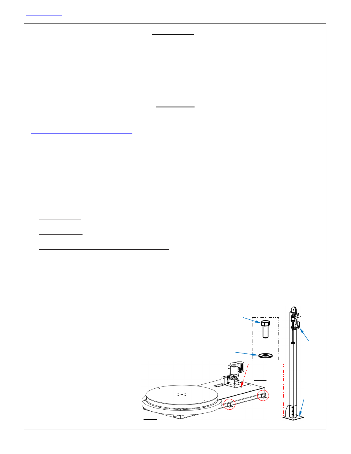
•DO NOT exceed the capacity of the unit. See Label 287 in Labeling diagram on p. 15.
•DO NOT stand, or sit, on the turntable or on the load.
•Loads must not extend over the shelves of the cart.
•Install the machine indoors on even, level surfaces capable of supporting it and a maximum capacity load. The
wrapping machine must not be exposed to the outdoor environment.
•Keep hands, clothing, etc. out of contact with all moving parts of the machine during operation.
•BEFORE using the wrapping machine, instruct all bystanders to clear of the machine and the load.
•During operation, stand with the mast between yourself and the turntable.
•DO NOT activate the turntable UNLESS the load is centered on it and stable. Be prepared to stop the turntable,
because rotation can cause the load become unstable. An unstable load might topple during the wrapping process.
EVERY person in the area should remain far enough away from the machine to avoid contact with the load if it falls.
Higher rotation speed might cause an unstable load to slide off of the turntable.
•DO NOT continue to use the machine if you observe abnormal motion or noise. Immediately tag the unit “Out of
service” and report the problem to maintenance personnel.
•If you notice a malfunction during operation, DO NOT attempt to resolve it unless you are both authorized to do so
and certain that it will be safe to use afterwards. The unit must be in normal operating condition whenever it is used.
See Inspections & Maintenance on p. 14).
•Inspect the product as directed on page 14. DO NOT use the machine unless it is in normal condition.
•DO NOT use this machine UNLESS all product labels are readable and undamaged. See Labeling Diagram, p. 15.
Proper use, maintenance, and storage are essential for this product to function properly.
oAlways use this product in accordance with the instructions in this manual and consistent with any training relevant
to machines, devices, etc. used in conjunction with this product.
oPeriodically lubricate the chain.
oKeep the product clean & dry.
oOnly use approved replacement parts.