Heath Company 336 User manual
instruction sheet
FOR THE HEATHKIT HIGH VOLTAGE PROBE model no. 336
DADTC 1l<*T
rAK IO L10 1(1incprt thp rp<*i<5tnr and hodv snrin^-insu-
lntn*r qippup aQc;pTnV>1v into thp nrohp hodv
432-1 1uonnector with thp rp<?ic:tnr toward the tin Refer to the
476-Z 1rTOOe DOQy
Aiff H
2-47 1iuyu megonin resistor
250-6 1Hex collar screw {)otrip 1/4 01 insulation irom Dotn enas 01
260-1 1Alligator clip both test leads.
258-2 1Tip spring
t)Unscrew the cap from the phone plug and
258-3 1Body spring
70-1 1Insulator sleeve insert one end of each test lead through the
438-3 1Phone plug cap as shown. Solder the red test lead
341-1 1Length black test lead to the center lug, and solder the black test
341-2 1Length red test lead lead to the outside lug.
595-490 1Instruction manual
NOTE: HANDLE THE 1090 MEGOHMRESISTOR
WITH CARE.
()Replace the cap on the phone plug.
ASSEMBLY INSTRUCTIONS
()Remove the screw from one end of the
1090 megohm resistor and replace it with
the collar screw. Now screw the body
Spring onto the long part of the collar
screw.
( ) Slip the body spring into the insulator
sleeve (large end first).
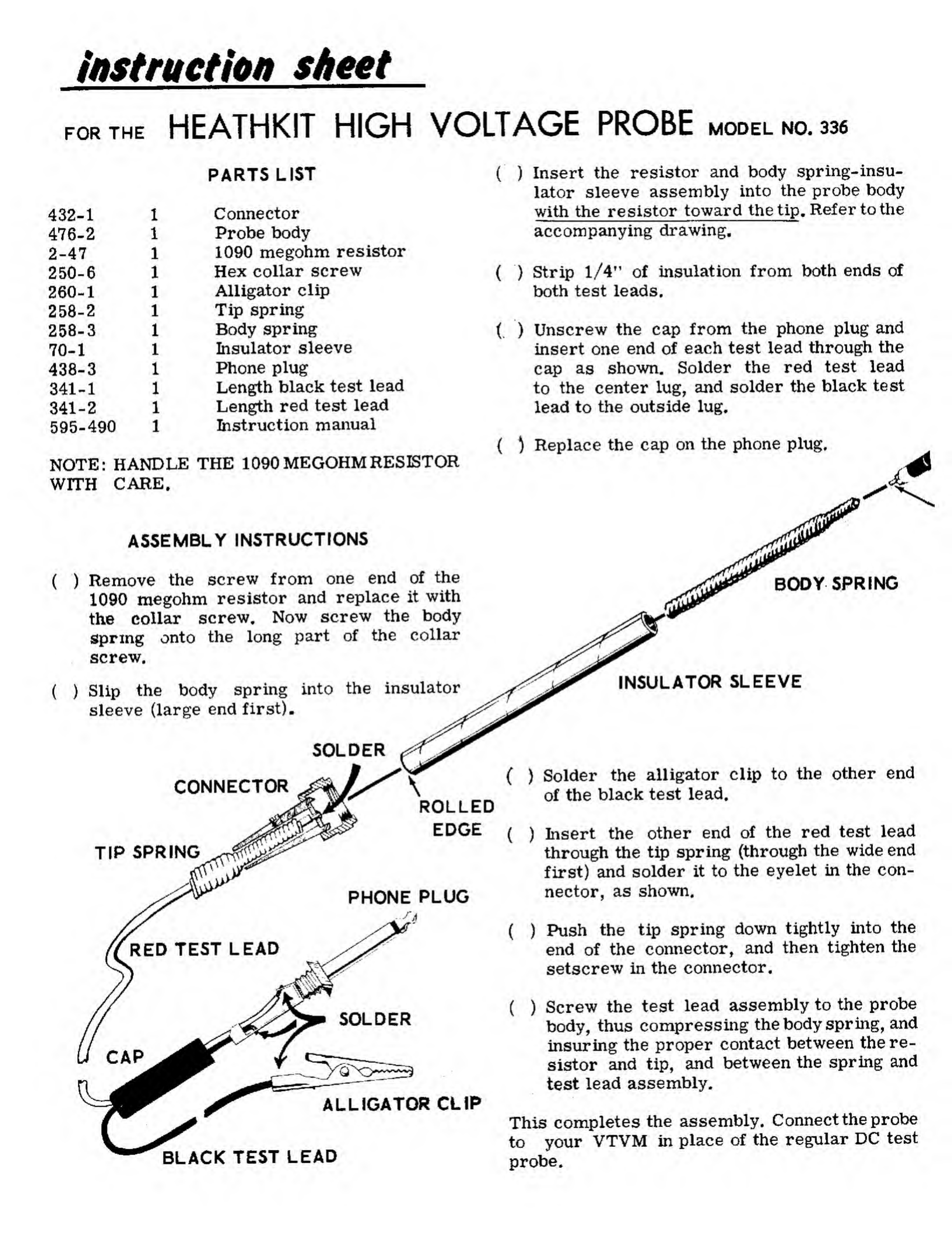
BODY SPRING
SOLDER
CONNECTOR
TIP SPRING
PHONE PLUG
INSULATOR SLEEVE
ROLLED
EDGE (
)Solder the alligator clip to the other end
of the black test lead.
)Insert the other end of the red test lead
through the tip spring (through the wide end
first) and solder it to the eyelet in the con-
nector, as shown.
ALLIGATOR CLIP
BLACK TEST LEAD
()Push the tip spring down tightly into the
end of the connector, and then tighten the
setscrew in the connector,
()Screw the test lead assembly to the probe
body, thus compressing the body spring, and
insuring the proper contact between the re-
sistor and tip, and between the spring and
test lead assembly.
This completes the assembly. Connect the probe
to your VTVM in place of the regular DC test
probe.
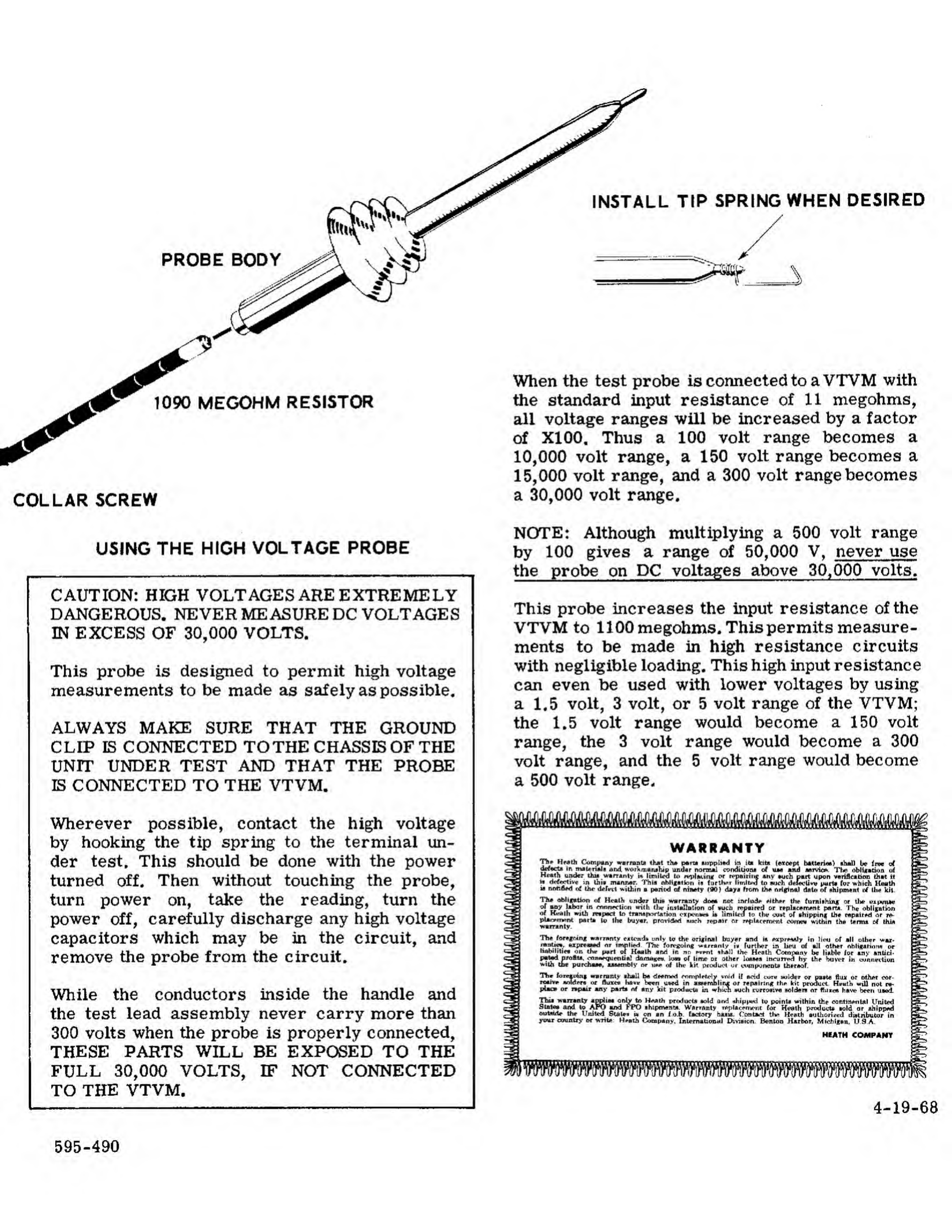
PROBE BODY
1090 MEGOHM RESISTOR
COLLAR SCREW
USING THE HIGH VOLTAGE PROBE
CAUTION: HIGH VOLTAGES ARE EXTREMELY
DANGEROUS. NEVER MEASURE DC VOLTAGES
IN EXCESS OF 30,000 VOLTS.
This probe is designed to permit high voltage
measurements to be made as safely as possible.
ALWAYS MAKE SURE THAT THE GROUND
CLIP IS CONNECTED TOTHE CHASSIS OF THE
UNIT UNDER TEST AND THAT THE PROBE
IS CONNECTED TO THE VTVM.
Wherever possible, contact the high voltage
by hooking the tip spring to the terminal un-
der test. This should be done with the power
turned off. Then without touching the probe,
turn power on, take the reading, turn the
power off, carefully discharge any high voltage
capacitors which may be in the circuit, and
remove the probe from the circuit.
While the conductors inside the handle and
the test lead assembly never carry more than
300 volts when the probe is properly connected,
THESE PARTS WILL BE EXPOSED TO THE
FULL 30,000 VOLTS, IF NOT CONNECTED
TO THE VTVM.
INSTALL TIP SPRING WHEN DESIRED
ftfr<r
When the test probe is connected to aVTVM with
the standard input resistance of 11 megohms,
all voltage ranges will be increased by afactor
of XI00. Thus a100 volt range becomes a
10,000 volt range, a150 volt range becomes a
15,000 volt range, and a300 volt range becomes
a30,000 volt range.
NOTE: Although multiplying a500 volt range
by 100 gives arange of 50,000 V, never use
the probe on DC voltages above 30,000 volts.
This probe increases the input resistance of the
VTVM to 1100 megohms. This permits measure-
ments to be made in high resistance circuits
with negligible loading. This high input resistance
can even be used with lower voltages by using
a1.5 volt, 3volt, or 5volt range of the VTVM;
the 1.5 volt range would become a150 volt
range, the 3volt range would become a300
volt range, and the 5volt range would become
a500 volt range.
WARRANTY
Thp Hr*th Company warrants that tha para tnpphed in its kite (except bUterua) ihal) be free of
drfecta in material! and workumruhip undar normal condiUoni of uh And Mrvic*. The obligation erf
;7*™* m™^ti»ib ana war* marump unaar normal conaiuom or uh and mtvh*.
Heath under thu warranty i* limilrd to replAcintf or repairing any *uch part upon verification that it
udefective in Uiiv mannar. Thia obligation ii further limited to such d«?f*cUvw parts fur which Heath
unotified of the deffi'l within aperiod of ninety (90) day* from th* origin*] date of thipnunt of Ihe kit-
The obligation of Hcalh under this warranty doe* not mrlude either the fumiihin^ or tiw t»xt*-iue
jfw y!*bar in mnnrclion with tlw installation of *uch repaired or replacement part*. Theobligation
of HtfAlh with reipact to transportation cxpen** i* limiltd to (h* cu*t of shipping the repaired or r*-
plar*m*nt patta U> the buyer provide unrh repair or replacement comeu within the tentu of Ihia
warranty.
Tlie (oregoing warranty extend* unly to the original buyer and ia AxprMrfy in lieu of all olher war-
F?^?*/ "P"1^nr ««P The fon>«oiog vtrranly in further in lieu of all other obligation* or
liabilities on the part of HaaLh and in nn event *hall the Heath Company be liable for any antici-
pated profit*, mn**quentiAl damage*. low of lime 01 other Icasea itirurr^d hy the buyer in wnnetfiun
wilh the purchaae, aaoambly or u*e of Ihu kit product ur components thereof
The foreauinj warranty ihall be d**med <*nmr>le»cly void if add cure wilder or pasta fliu or other cor-
rotive anldrn or Huh* havir been uwd in assembling or repairing the kit product Ht-ulh will not ra-
pimca or repair any parte rrf any kit product in which *uch twroaive boIdem or flwieft hftve been uwd
warranty appliaa only tn H^ath product* *>ld and shipped tu point* within the continental United
Stat** and to APO and FPO ihipment* Warranty replacement for Heath product* told or ahippod
outeirte the Vmted Stale* won an Lob. factory haaa. Contact the Heath authorised distributor in
"country or write Heath Company, International Division, Benton Harbor, Michigan, USA.
r.»VA
4-19-68
595-490
Popular Measuring Instrument manuals by other brands

LeCroy
LeCroy DXC100A manual

SYSMEX
SYSMEX XW-100 Start-Up Quick Guide

AR
AR DC7230A Operating and service manual

Start italiana
Start italiana TOKHEIM Pro Gauge XMT-SI-485-LOG installation manual

ENERGY SUPPORT CORPORATION
ENERGY SUPPORT CORPORATION ISS-101 instruction manual

Southwire
Southwire M555TP operating instructions


turck
turck FCI-X-H114 Series quick start guide

Haldex
Haldex Modular Trailer System Installation & service manual

Luxinar
Luxinar MULTISCAN VS user manual

Siemens
Siemens SITRANS F US Hardware installation instructions

Keysight
Keysight PNA Series Installation and service guide

Fluke
Fluke 3310-PR instruction sheet