manuals.online logo
Brands
  1. Home
  2. •
  3. Brands
  4. •
  5. Heatilator
  6. •
  7. Indoor Fireplace
  8. •
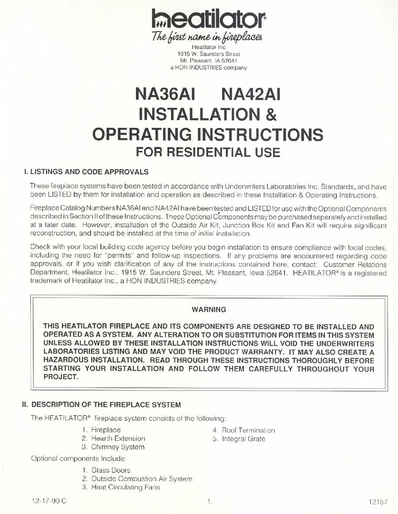
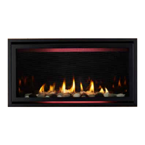
  9. Heatilator ALK-36 User manual

Heatilator ALK-36 User manual

1
Heatilator • ALK-36, ALK-48, ALK-60, ALK-72 Installation Instructions • 2300-947 Rev. J • 3/18
ALK-36, ALK-48, ALK-60, ALK-72
Models: Models: CRAVE/CRAVE-B
Installation Instructions
Leave this instruction with party responsible for
use and operation.
CAUTION! Do not install damaged components. If
you received components that are damaged, contact
your dealer for assistance.
CAUTION! Risk of Cuts or Abrasions. Wear protective
gloves and safety glasses during installation. Sheet metal
edges are sharp.
KIT CONTENTS:
• LED 12 Volt Power Supply
• LED/Wire/Tray Assembly
• AUX300 Module
• Sheet metal screws (2)
• Velcro (1 inch)
Note: This appliance does include a manual gas shutoff
valve that is located in the valve compartment. This manual
gas shutoff valve is accessible for service by removing the
decorative front and the vanity panel. Depending upon
local code, an additional manual gas shutoff, in a readily
accessible area may be required and located upstream from
the appliance.
5. Turn the gas shutoff handle to the “OFF” position to
shut off the gas supply.
6. Remove lower access cover panel if nishing is not
completed.
7. To remove the glass assembly:
Locate the spring latches that are on the upper edge
of the glass frame of the appliance.
Use both index ngers to release spring latches.
Allow glass to tilt forward. Grasp glass on the upper
return lip of glass frame and lift up and out. The glass
should lift easily out of the bottom retaining lip.
8. Remove interior media and refractory from the unit if
already installed.
9. Remove the media tray. It is attached to the interior
rebox bottom with screws.
10. Remove the two screws that attach the pilot to the
burner. See Figure 1.
11. Remove the four screws securing the burner to the
rebox sides and disengage burner from orice. Re-
move burner.
12. Remove the eight screws that secure the glass window.
Remove the bottom glass. See Figure 2 and Figure
3. Handle with care.
13. Remove tray from appliance and discard.
Preparation
CAUTION! Risk of Burns! The replace should be
turned off and cooled before servicing.
1. Remove the decorative front.
2. Remove the vanity panel from bottom of glass frame.
3. Remove screws on left and right sides of component
heat shield and lift it out of the control cavity.
4. Unplug the 6V transformer from the junction box.
This will turn the power off to the appliance.
WARNING! Risk of Injury! Turn off gas supply and dis-
connect electrical power before accessing electrical com-
ponents inside appliance.
DANGER
HOT GLASS WILL
CAUSE BURNS.
DO NOT TOUCH GLASS
UNTIL COOLED.
NEVER ALLOW CHILDREN
TO TOUCH GLASS.
A barrier designed to reduce the risk of
burns from the hot viewing glass is provided
with this appliance and shall be installed for
the protection of children and other at-risk
individuals.
2Heatilator • ALK-36, ALK-48, ALK-60, ALK-72 Installation Instructions • 2300-947 Rev. J • 3/18
INSTALLATION
1. Place LED Tray Assembly into appliance through the
bottom glass opening.
2. Secure the LED power supply with two screws.
3. Attach the AUX to the component tray with velcro.
Refer to Figure 4 and Figure 5 for the following steps:
4. Plug the light wire harness into the LED power supply.
5. Plug the LED power supply into AUX2 on the AUX
module.
6. Using self-tapping screws, secure green ground wire of
cord assembly to component tray.
7. Plug the AUX module into the junction box and control
module.
8. Place wires in wire management clips to prevent touch-
ing the rebox.
9. Reinstall the bottom glass, burner, pilot and media tray.
10. Place media according to instructions include with me-
dia kit.
11. Reinstall glass assembly.
12. Plug the 6V transformer into the junction box.
13. Reinstall component heat shield.
Figure 1. Base Pan with Burner and Pilot Cover
PILOT SHIELD
BURNER ASSEMBLY
4836 & 6048
MEDIA TRAY
BURNER ASSEMBLY
7260 & 8472
Figure 2. Remove Screws on Bottom Glass
Figure 4. Electrical Components in Position
JUNCTION BOX
LED POWER
SUPPLY
AUX
CONTROL MODULE
BATTERY
TRAY
COMPONENT
HEAT SHIELD
CAUTION! Risk of Overheating! Component heat shield
MUST be installed before operating appliance. Electrical
components will be damaged.
14. Turn on gas and electric power to appliance.
Figure 3. LED Tray Assembly in Position
Model Size 36/48/60/72
3
Heatilator • ALK-36, ALK-48, ALK-60, ALK-72 Installation Instructions • 2300-947 Rev. J • 3/18
Figure 5. LED Wiring Diagram
LED LIGHT TRAY (36 INCH MODELS)
TO JUNCTION
BOX (110V)
MODULE
I
S
FLAME
SENSE IGNITER RC300 4.5V DC
(AAA X 3)
TO
JUNCTION
BOX 110VAC
ORANGE
(PILOT)
GREEN
(MAIN)
FLAME
MODULATION
AUX300 MODULE
AUX 1
AUX 2
FAN
GROUND
BROWN
BLACK
RED
BATTERY PACK
6V DC
LED CONTROL
LED LIGHT TRAY (60 INCH MODELS)
LED LIGHT TRAY (72 INCH MODELS)
LED LIGHT TRAY (48 INCH MODELS)
4Heatilator • ALK-36, ALK-48, ALK-60, ALK-72 Installation Instructions • 2300-947 Rev. J • 3/18
Heatilator, a brand of Hearth & Home Technologies
7571 215th Street West, Lakeville, MN 55044
www.heatilator.com
Please contact your Heatilator
dealer with any questions or concerns.
For the location of your nearest Heatilator dealer,
please visit www.heatilator.com.
LED Operation
The LED lights are operated using the auxiliary (AUX2)
function on the remote control. See Figure 6.
AUX2 Function
• Press the MENU button to activate the menu.
• Using the UP and DOWN arrows highlight the AUX2 icon
and press SELECT.
• Use the UP and DOWN arrows to turn the AUX2 ON or
OFF, then press SELECT. The AUX2 function can be
either be turned ON or OFF.
NOTICE: The system will remember the previous AUX1
and AUX2 setting from the menu. However, when the re-
place is turned OFF both AUX1 and AUX2 will be turned
off. AUX and AUX2 can be activated when the ame is off
from the remote’s OFF mode. When the replace is turned
back ON the AUX1 and AUX2 settings will be restored to
the previous ON setting.
FIREPLACE STATUS
THERMOSTAT
THERMOSTAT DESIRED
TEMP SETTING
FLAME HEIGHT
FAN SPEED
ADJUSTABLE
AUXILIARY
ADJUSTABLE
OUTPUT (ON/OFF)
TIMER DISPLAY/FUNCTION
CONSTANT PILOT
ROOM TEMP
DISPLAY
FUNCTION LEVEL
INDICATOR
LOW BATTERY
INDICATOR
TRANSMISSION
INDICATOR
CHILD LOCK
INDICATOR
Figure 6. RC300 Display Screen - Aux2 Function Highlighted
PART NUMBER DESCRIPTION
2273-308 LED Power Supply
2300-014 LED Strips/Wire Assembly
2166-335 AUX300
Service Parts

This manual suits for next models

5

Other Heatilator Indoor Fireplace manuals
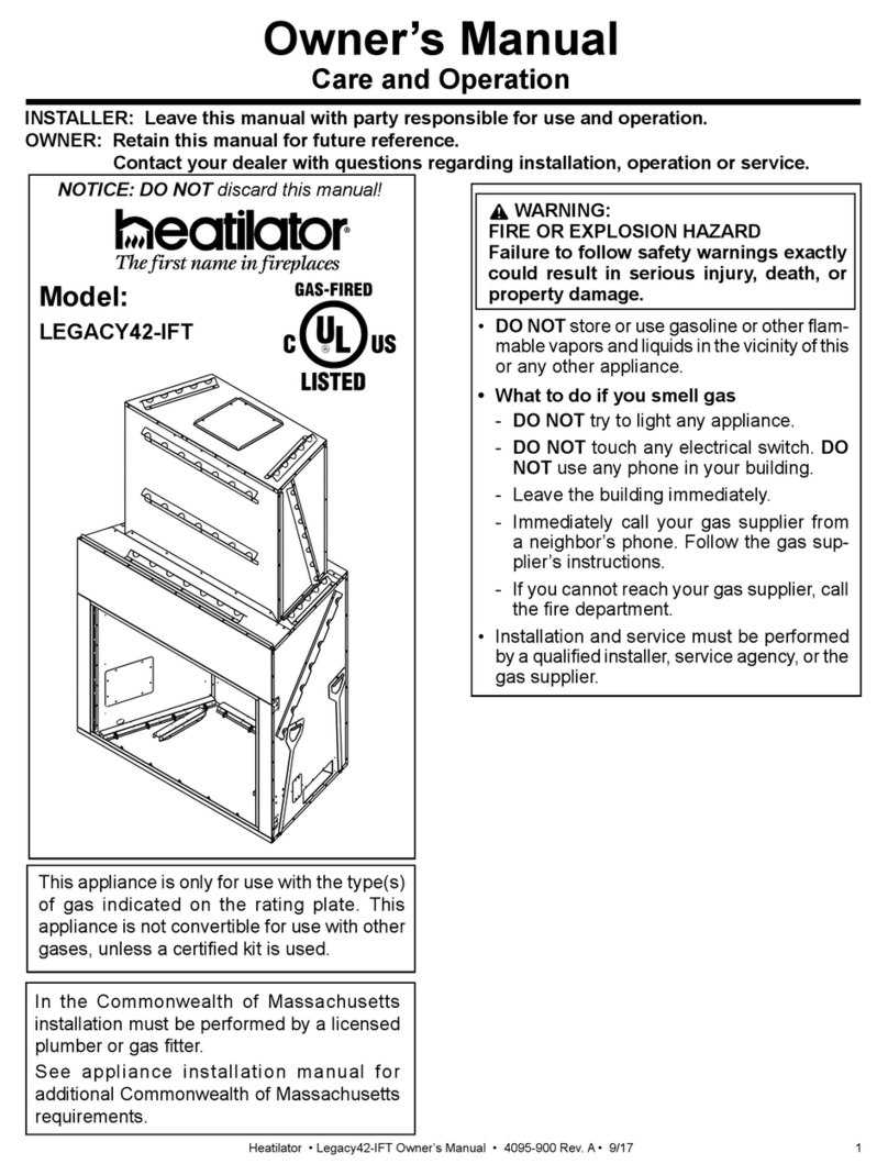
Heatilator Wood Burning Fireplace A36C User manual

Heatilator

Heatilator Wood Burning Fireplace A36C User manual

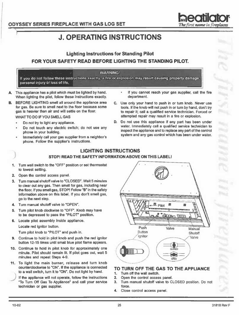
Heatilator RAVE3012I User manual

Heatilator

Heatilator RAVE3012I User manual

Heatilator CB4236IR User manual

Heatilator

Heatilator CB4236IR User manual

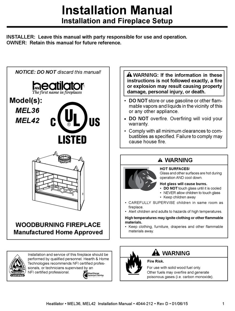
Heatilator NNXT4236IF User manual

Heatilator

Heatilator NNXT4236IF User manual

Heatilator Wood Burning Fireplace ST36D User manual

Heatilator

Heatilator Wood Burning Fireplace ST36D User manual

Heatilator CONSTITUTION C-40 User manual

Heatilator

Heatilator CONSTITUTION C-40 User manual

Heatilator A36R User manual

Heatilator

Heatilator A36R User manual

Heatilator ICON I100 Manual

Heatilator

Heatilator ICON I100 Manual

Heatilator Eco-Choice WS18-AU User manual

Heatilator

Heatilator Eco-Choice WS18-AU User manual

Heatilator CRAVE4836-B User manual

Heatilator

Heatilator CRAVE4836-B User manual

Heatilator Gas Fireplace GBFL4136I User manual
Heatilator

Heatilator Gas Fireplace GBFL4136I User manual

Heatilator Gas Fireplace GDST3831I User manual

Heatilator

Heatilator Gas Fireplace GDST3831I User manual

Heatilator CL36D User manual

Heatilator

Heatilator CL36D User manual

Heatilator NBV30-IFT Instruction Manual

Heatilator

Heatilator NBV30-IFT Instruction Manual

Heatilator CD4236-MOD User manual

Heatilator

Heatilator CD4236-MOD User manual

Heatilator LM42 User manual

Heatilator

Heatilator LM42 User manual

Heatilator CONSTITUTION C-40 User manual

Heatilator

Heatilator CONSTITUTION C-40 User manual

Heatilator I60 Safety guide

Heatilator

Heatilator I60 Safety guide

Heatilator Wood Burning Fireplace I100 User manual

Heatilator

Heatilator Wood Burning Fireplace I100 User manual

Heatilator ST42A User manual

Heatilator

Heatilator ST42A User manual

Heatilator BIR42-B User manual

Heatilator

Heatilator BIR42-B User manual

Heatilator CONSTITUTION C-40 User manual

Heatilator

Heatilator CONSTITUTION C-40 User manual

Heatilator Direct Vent Gas Appliance CNXT4236IH User manual

Heatilator

Heatilator Direct Vent Gas Appliance CNXT4236IH User manual

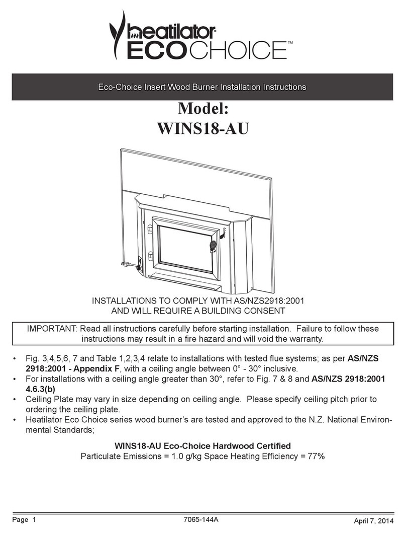
Heatilator ECO CHOICE WINS18-AU User manual
Heatilator

Heatilator ECO CHOICE WINS18-AU User manual

Popular Indoor Fireplace manuals by other brands

Superior VRT2036B Installation and operation instructions

Superior

Superior VRT2036B Installation and operation instructions

Desa VICTORIAN VV36ENB SERIES OWNER'S OPERATION AND INSTALLATION MANUAL

Desa

Desa VICTORIAN VV36ENB SERIES OWNER'S OPERATION AND INSTALLATION MANUAL

Luxor Riviera-66 Installation and owner's manual

Luxor

Luxor Riviera-66 Installation and owner's manual

Napoleon GDS26P-1 Installation and operating instructions

Napoleon

Napoleon GDS26P-1 Installation and operating instructions

Temco ADF3324N installation instructions

Temco

Temco ADF3324N installation instructions

Napoleon GVF30-N Installation and operation instructions

Napoleon

Napoleon GVF30-N Installation and operation instructions

Travis Industries 21E owner's manual

Travis Industries

Travis Industries 21E owner's manual

Muskoka 310-42-45 user manual

Muskoka

Muskoka 310-42-45 user manual

Montigo PL52DFN-I Installation & maintenance manual

Montigo

Montigo PL52DFN-I Installation & maintenance manual

Nordica INSERTO 60 Instructions for installation, use and maintenance

Nordica

Nordica INSERTO 60 Instructions for installation, use and maintenance

kozy heat Z-42 Installation and operation manual

kozy heat

kozy heat Z-42 Installation and operation manual

Element4 SKY Series installation manual

Element4

Element4 SKY Series installation manual

Dimplex milano-ef user guide

Dimplex

Dimplex milano-ef user guide

Faber JELLING installation guide

Faber

Faber JELLING installation guide

Home Decorators WSFP46ECHD-5 Assembly instructions

Home Decorators

Home Decorators WSFP46ECHD-5 Assembly instructions

Astria Envy35TEN Installation and operating instruction manual

Astria

Astria Envy35TEN Installation and operating instruction manual

Sunjoy L-OF117PST-A manual

Sunjoy

Sunjoy L-OF117PST-A manual

Valcourt S42 owner's manual

Valcourt

Valcourt S42 owner's manual

manuals.online logo
manuals.online logoBrands
  • About & Mission
  • Contact us
  • Privacy Policy
  • Terms and Conditions

Copyright 2025 Manuals.Online. All Rights Reserved.