HeatLink Smart System User manual

SYSTEM
SMART
FUSE
34 567812
Pump Boiler CO Dew
Point
R C
Reset
G1 G2 Network
Status
Pair
24Vac
0 15min Int Ext NC NO
Antenna Actuator
Delay
Off
Dry Contacts
3
4
5
6
7
8
1
2
Pump
Boiler
CO
Dew
Point
R
C
Reset
G1
G2
Network
Status
Pair
24Vac
0
15
min
Int
Ext
NC
NO
Antenna
Actuator
Delay
Off
Dry Contacts
Dry Contacts
®
LinkHeat
1 2 3 4 5 6 7
PM
Auto Manual
On Off
Installation and Set Up Manual
2018

2
®
Link
Heat
Table of Contents
Product Compliance & Safety Information.................... 3
Introduction - The HeatLink Smart System ................... 5
Overview ...................................................................................5
Smart System Installation Quick Guide.............................6
HeatLink App ...........................................................................7
Installation - Wireless Internet Gateway...........................8
Wireless Gateway LED Indications..................................................9
Wireless Gateway Functions..............................................................9
Installation - Wireless Digital Thermostat ...................... 10
Thermostat Power Up Sequence...................................................11
Thermostat Icons & Functions .......................................................12
Installation - StatLink® 8 Zone Wireless Module
13
Installation - External Antenna (Optional)...................... 15
StatLink®8 Zone Wireless Module Buttons, and Jumpers
16
StatLink®8 Zone Wireless LED Indications................................16
Installation - Wireless Valve Actuator............................. 17
Wireless Valve Actuator LED Indications ....................................18
Installation - Wireless Relay ............................................... 19
Wireless Relay LED Indications .............................................. 20
Installation - Wireless Door/Window Sensor................. 21
Offline System Setup .......................................................... 22
Online System Setup - Wireless Internet Gateway &
App.......................................................................................... 22
Systems and Settings.......................................................... 24
Set Up - Underfloor Heating System .............................. 25
Offline - Thermostat Groups............................................ 28
Set Up - Radiator/Baseboard Systems............................ 29
Adaptive Learning Mode..................................................................32
Changing the Control Method with App ...................................32
Online - Changing the Control Method Manually 33
Offline - Changing the Control Method Manually 34
Setup - Wireless Receiver (RX1 - Boiler Switching)
36
Set Up - Wireless Relay (RX2 - Single Room) ............... 38
Set Up - Door/Window Sensor......................................... 40
Set Up - Smart Plug............................................................. 40
Device Parameters .......................................................... 41
Offline - Thermostat Set Up............................................... 41
Offline - Setting the Time.................................................................41
Offline - ID Mode ................................................................................42
Offline - Setting Mode Temperatures..........................................42
Manual Set Point Temperature Override....................................42
Offline - Heating Schedules ............................................................43
Offline - Setting Heating Schedules.............................................44
Installer Parameters Menu...............................................................45
Offline - Select ºF or ºC.....................................................................45
Thermostat Functions & Parameters ...........................................46
Wiring Schematics .........................................................47
Wiring - StatLink® 8 Zone Wireless Wiring Center
47
Wiring - Wireless Relay (RX1)........................................... 48
Wiring - Wireless Relay (RX2).......................................... 48
Troubleshooting ............................................................. 49
Factory Reset........................................................................ 49
Reset the Wireless Internet Gateway .........................................49
Reset Thermostats.............................................................................49
Reset StatLink®8 Zone Wireless Module.................................50
Reset Wireless Relay.........................................................................50
Reset the Smart Plug........................................................................50
Reset Wireless Valve Actuator ......................................................51
Reset the Door/Window Sensor..................................................51
Thermostat Error Codes .................................................... 52
FAQ - Frequently Asked Questions...............................53

3
®
Link
Heat
This equipment has been tested and found to comply with the limits for a Class B digital device, pursuant
to Part 15 of the FCC Rules. These limits are designed to provide reasonable protection against harmful
interference in a residential installation. This equipment generates uses and can radiate radio frequency
energy and, if not installed and used in accordance with the instructions, may cause harmful interference
to radio communications. However, there is no guarantee that interference will not occur in a particular
installation. If this equipment does cause harmful interference to radio or television reception, which can be
one or more of the following measures:
• Reorient or relocate the receiving antenna.
• Increase the separation between the equipment and receiver.
• Consult the dealer or an experienced radio/TV technician for help.
user’s authority to operate the equipment.
This device complies with part 15 of the FCC Rules. Operation is subject to the following two conditions: (1)
This device may not cause harmful interference, and (2) this device must accept any interference received,
including interference that may cause undesired operation.
This device complies with Industry Canada’s licence-exempt RSSs. Operation is subject to the following two
conditions:
(1) This device may not cause interference; and
(2) This device must accept any interference, including interference that may cause undesired operation of
the device.
Le présent appareil est conforme aux CNR d'Industrie Canada applicables aux appareils radio exempts de
licence. L'exploitation est autorisée aux deux conditions suivantes :
(1) l'appareil ne doit pas produire de brouillage, et
(2) l'utilisateur de l'appareil doit accepter tout brouillage radioélectrique subi, même si le brouillage est
susceptible d'en compromettre le fonctionnement.
Product Compliance & Safety Information

4
®
Link
Heat
About Us
HeatLink is a multi-system supplier of potable water and radiant hydronic heating/cooling and snow melt
systems that began as a family-owned business servicing a number of industries, including HVAC.
The company grew to meet the needs of builders, contractors, and architects, and began designing
and installing radiant heating systems in 1985. Since then HeatLink has grown into an industry leading
manufacturer of radiant heating, cooling, and potable water systems for residential and commercial
applications throughout the world.
our snow melt systems create safer public and private spaces that reduce liability for property owners, reduce
maintenance, and ensure accessibility. Our well engineered plumbing systems provide peace of mind for
builders and contractors.
1996. The company began manufacturing PEX-a tubing in 1998, and now supplies the highest quality PEX-a
systems to customers throughout North America, and parts of Europe and Asia.
HeatLink works with a network of experienced and successful partner agencies to meet the design, system
installation, and training needs of the construction industry, designers, and architects.
HeatLink was built on a strong family work ethic and value system that remains the foundation for our
continuing growth and industry leadership role.

5
®
Link
Heat
About Us Introduction - The HeatLink Smart System
The HeatLink Wireless System uses the Zigbee protocol (see www.zigbee.org for more information) to
connect all devices on a contained network, allowing them to communicate easily and securely without the
Connecting the system to the Internet (Online) via a router allows the HeatLink app to monitor and adjust
your system from anywhere in the world (after the initial setup is complete, see page 22). In an Online
System the devices continue to communicate with each other via the Zigbee network, and will function as per
your settings even if the Internet connection is severed.
Overview
System Components
Router (from others) - required for an Online system. Connects the Wireless gateway to the internet.
46801 Wireless Thermostat - has an easy to use interface, and a sleek modern design. It can be configured to
work with a variety of radiant heating systems as a progrmmable thermostat, or digital thermostat.
43304 Wireless Smart Plug - requires an Online system to operate, and allows you to control the on/off
function of lights and some electronics, and set custom programs for system operation (using the app).
43303 Wireless Door/Window Sensor - requires an Online system to operate, and allows you monitor your
home windows and doors, as well as set custom programs for system operation (using the app).
43302 Wireless Relay - can be configured as a Boiler Relay (RX1), or Standalone Relay (RX2) depending on your
system configuration.
56401 Wireless Valve Actuator - is easily installed on a radiator valve to control heat supply to a room (requires
a 46801 Wireless Thermostat). Can be used in Online or Offline systems.
40328 StatLink® 8 Zone Wireless Module - connects your wireless thermostats
to the zone actuators, and controls the boiler, system pump, etc.
HeatLink App (device from others) - Controls your Online Smart System, and allows you to monitor from
anywhere.
43301 Wireless Gateway - required for all HeatLink® Smart Systems to function. Connects all devices to the
Zigbee network, and to the internet (Online system configuration).
Additional Online System Components
Additional Components by others

6
®
Link
Heat
1. Install HeatLink®app, and set up account (online only).
2. Install system components:
i. Wireless gateway
ii. StatLink®wireless module
iii. HeatLink®wireless thermostat
iv. Wireless relay
v. Wireless valve actuator
vi. Smart plug (online only)
vii. Door/window sensor (online only)
3. Connect wireless gateway to app.
4. Pair components:
i.
• StatLink®8 zone wireless module
• wireless thermostats
ii. Radiator/Baseboard systems
• wireless thermostats
• wireless valve actuators
iii. Boiler Switching (RX1)
• wireless thermostat (REC1 mode)
• wireless relay (RX1 mode)
iv. Individual Zone Relay
• wireless thermostat (REC2 mode)
• wireless relay (RX2 mode)
v. Peripherals
• smart plug(s)
• door/window sensor(s)
5. Set up heating programs
Smart System Installation Quick Guide

7
®
Link
Heat
HeatLink App
If using a system connected to the Internet, you can download the HeatLink® app from Google Play or the
App Store.
then proceed to "Device Pairing & System Set Up" on page 22
As a first time user please complete a few
simple steps to manage your account and
equipment. Let’s get started setting up your
new system.
Welcome to HeatLink®!
Create your profile
First Name
Last Name
Email Address
Confirm Email Address
Back HeatLink
Google Play and the Google Play logo are trademarks of Google LLC.
Apple, the Apple logo, iPhone, and iPod touch are trademarks of Apple Inc., registered in the U.S. and other countries. App Store is a service mark of Apple Inc.,
registered in the U.S. and other countries.

8
®
Link
Heat
Device Installation
factors, the device(s) may need to be located in a common location for pairing.
Avoid installing devices in metal cabinets as this may interrupt the signals.
Please follow these instructions when installing your system components; the installation process for all
Installation - Wireless Internet Gateway
The Wireless Internet Gateway should be installed in a location free from radio signal interference, close to a
120V plug and your Internet router (Online installations).
Step 1
Step 2 Remove the port cover from the bottom of the Wireless Internet Gateway by twisting it ~
counter-clockwise.
LOCK UNLOCK
Wireless Internet
gateway
USB to
micro USB cable
USB power
adapter
To Internet router
(by others)
Plug into 120V outlet
Multi button
LED light
ring
Ethernet cable
Step 3 If connecting to the Internet and app, attach the Ethernet network cable to the gateway, then to
your router.
Step 4 Plug micro USB into the gateway, then plug the USB into the plug adapter.
Step 5 Plug the adapter into the wall.
Step 6 If desired, mount the port cover to a wall or other surface. Replace the port cover.

9
®
Link
Heat
Step 7 Once plugged in, the Wireless Internet Gateway will go through the startup process.
Wireless Gateway LED Indications
Wireless Gateway Functions
If the gateway does not connect, see "Troubleshooting" on page 50.
®
LinkHeat
®
LinkHeat
®
LinkHeat
®
LinkHeat
®
LinkHeat
On, connected to local router
via Ethernet cable (not shown),
connected to app
On, not connected to local router
via Ethernet cable (not shown),
not connected to app
Ready for device pairing
(with or without network/
app connection)
Powering up, OR; On, connected to
local router via Ethernet cable (not
shown), not connected to app
On, attempting to connect,
or in Identify mode (with
or without network/app
connection)
Solid Blue
Solid Green Flashing Green
Solid Red Flashing Red
Function
Press
LED
Enter pairing mode Press multi button for 3+ seconds Flashes red
Exit pairing mode Press multi button for 3+ seconds
Enter/exit ID mode* Single press of multi button Flashes green
*ID mode is used to identify the components that are connected to your Smart System; each component will fl ash for
10 minutes, or until you exit ID mode with another single press of the multi button.
®
LinkHeat
®
LinkHeat
®
LinkHeat
®
LinkHeat
LED is solid Green
- Online, ready to
connect to app
LED is solid red -
with devices
LED flashes red LED flashes green

10
®
Link
Heat
Installation - Wireless Digital Thermostat
For best operation, the wireless thermostat should be installed in a draft-free area of the room, 4-5’ from the
Remove the back mounting plate by pulling from
the bottom, and out.
Attach the mounting plate to the desired spot
on the wall using the included mounting screws,
ensuring it is level.
Floor sensor
If using a floor sensor (sold separately) wire it into the terminal block
on the mounting plate. Install the included 4×AAA alkaline
batteries into the thermostat.
Replace the thermostat onto the backplate, hinging
from the top.

11
®
Link
Heat
Thermostat Power Up Sequence
complete before you are able to pair it with your gateway and devices.
®
LinkHeat
The Thermostat is ready to be
paired.
®
LinkHeat
The Zigbee software version
(example only).
®
LinkHeat
1 2 3 4 5 6 7
A B1 ON OFF
M12
PM
®
LinkHeat
Boot screen.
®
LinkHeat
The MCU software version
(example only).
See "Device Pairing & System Set Up" on page 22.

12
®
Link
Heat
Thermostat Icons & Functions
comfort. The modes and heating programs can be easily managed through the app in Online systems, or
M12
AM
PM
1 2 3 4 5 6 7
A B1 ON OFF
1
2 3 4 5 6 8
9
10
11
12
13
14
15
16
17
18
19
20
21
22
23
24
25
26
27 28
7
#Icon Function
1Indicates active heating mode.
2Sun: high comfortable temperature
3Cloudy: middle comfortable temperature
4Moon: low comfortable temperature
5
Programmable thermostat Program mode (Auto)
indicator: Indicates program is running, Auto On or
6Party mode indicator
7Vacation temperature indicator
8Frost temperature mode indicator (typically 5ºC, used
for extended periods of absence)
9Heating is on
10
network
11 Internet indicator: unit is linked to the Internet
12
13 Hot water indicator - thermostat is in Hot Water
mode
14
running(?)
15
reached
16 Low Battery indicator
17 Gear - indicates user setting mode is active
18 Master 1 or Master 2 (for prog only)- indicates the
current thermostat is a Master 1 or 2
19
Slave 1 or Slave 2 indicator (For Non-prog only)
- Indicates the current thermostat is a slave with
number 1 or 2.
20 Temporary manual override
21 HW Program mode(Auto) indicator: Indicates
22
HW Mode indicator: Indicates turn on for 1 period
a day, from Program 1 ON (start time) to Program 3
OFF (start time).
23 HW Mode indicator: Indicates Continuously On.
24
25 HW Mode indicator: Indicates Boost +1hr override.
26 Active schedule block
27 Current day of the week (1=Monday, 2=Tuesday, etc.)
28 Key lock indicator: Indicates the pressed key is locked.
Button
Press
Function
or
Short Increase or decrease setpoint
temperature.
Short Increase or decrease Day, Clock, Timer,
Party, Holiday, and Boost.
Short Select installer parameter menu.
or
Short Mode selection.
Long Long press (left) to return to home
display without saving.
Short
Short press (left) to return to the previous
screen when it is in user/installer setting
mode.
Short
Long Save and exit.
Long Enter the user settings.
+
Long Lock/Unlock
+ + Long Enter installer parameter settings.
13
®
Link
Heat
Step 1 Ensure that the wiring module is complete and not damaged.
Step 2
Step 3 If mounting using the included DIN rail, attach the DIN rail to the wall or backing board in an
appropriate location, ensuring it is level.
Step 4 If mounting the StatLink® 8 Zone Wireless Module directly to the wall or backing board, unscrew
the terminal block from the casing and attach to the wall or backing board, ensuring it is level.
FUSE
34 567812
Pump Boiler CO Dew
Point
R C
Reset
G1 G2 Network
Status
Pair
24Vac
0 15min Int Ext NC NO
Antenna Actuator
Delay
Off
Dry Contacts
8 Zone Wireless Module
40328
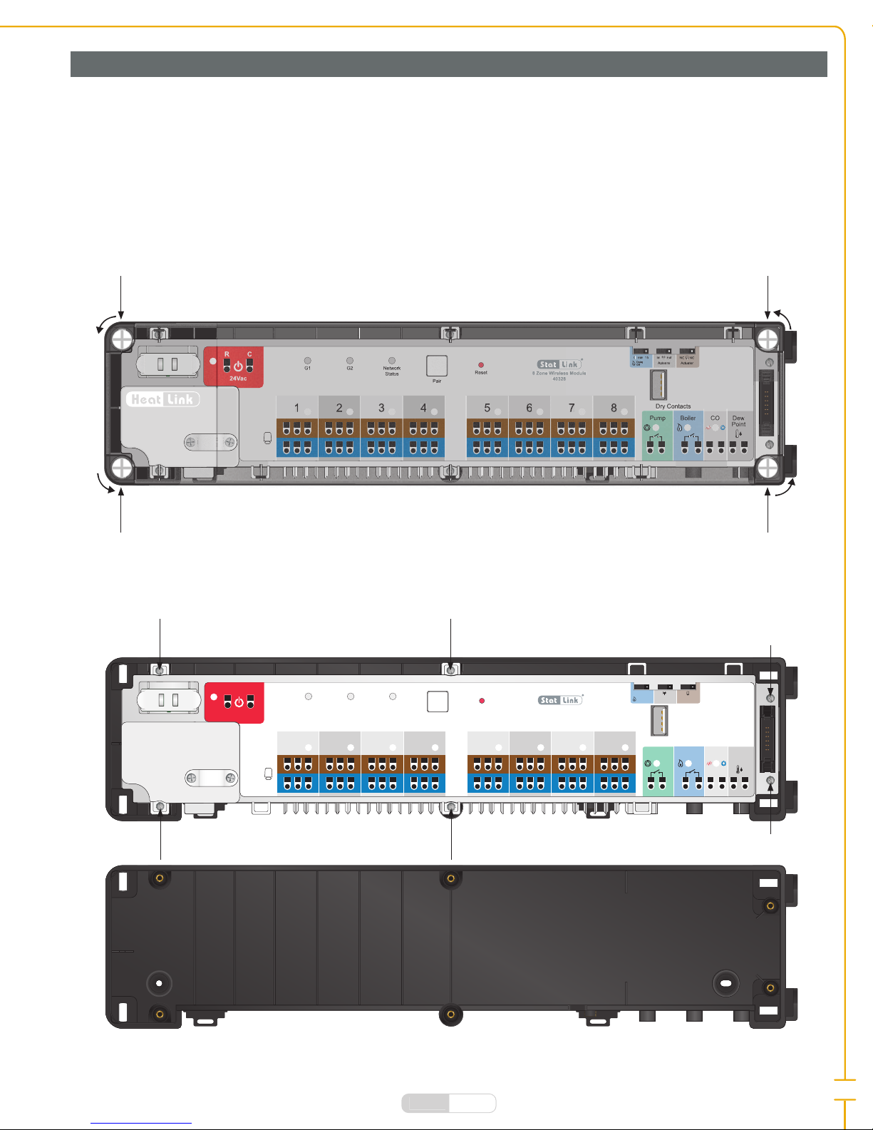
The HeatLink® StatLink® 8 Zone Wireless Module connects with your wireless thermostats using the Wireless
Internet Gateway, allowing you to easily control up to 24 actuators in 8 zones (3 per zone).
StatLink® 8 Zone Wireless Modules should be installed in a location that is accessible, clean, and dry - do not
mount the StatLink® 8 Zone Wireless Module below your piping or manifolds! Any water could damage the
Wireless Module and cause electrical shorts or fi re.
Installation - StatLink® 8 Zone Wireless Module
FUSE
34 567812
Pump Boiler CO Dew
Point
R C
Reset
G1 G2 Network
Status
Pair
24Vac
0 15min Int Ext NC NO
Antenna Actuator
Delay
Off
Dry Contacts
8 Zone Wireless Module
40328
3
4
5
6
7
8
1
2
Pump
Boiler
CO
Dew
Point
R
C
Reset
G1
G2
Network
Status
Pair
24Vac
0
15
min
Int
Ext
NC
NO
Antenna
Actuator
Delay
Off
Dry Contacts
Dry Contacts
8 Zone Wireless Module
40328

14
®
Link
Heat
Step 7 Wire up to 3 actuators per zone (see page 48 for wiring diagrams), to a maximum of 12 per
module.
Step 8 Wire your pump, boiler, change over valve and humidity sensor, if applicable (see page 48 for
wiring diagrams).
Step 9 Wire the 24V plug-in transformer (sold separately) to the wiring module.
Switch Function Diagram
minutes.
Note: The Pump/Boiler on delay, and the pump off delay are fi xed at 3 minutes.
Wireless Connection
external wireless antenna 43305)
Actuator Type
0 15min
Int Ext NC NO
Antenna Actuator
Delay
Off
0 15min
Int Ext NC NO
Antenna Actuator
Delay
Off
0 15min
Int Ext
NC NO
Antenna
Actuator
Delay
Off
0 15min
Int Ext
NC NO
Antenna
Actuator
Delay
Off
0 15min Int Ext
NC NO
Antenna
Actuator
Delay
Off
0 15min Int Ext
NC NO
Antenna
Actuator
Delay
Off
Step 5 Replace the terminal block into the black casing, securing all screws.
Step 6 Ensure the fuse is in place; remove fuse holder to verify (4A 5×20mm F4A4250VP).
FUSE
34 567812
Pump Boiler CO Dew
Point
R C
Reset
G1 G2 Network
Status
Pair
24Vac
0 15min Int Ext NC NO
Antenna Actuator
Delay
Off
Dry Contacts
8 Zone Wireless Module
40328
Step 10 Clip all wires into the strain reliefs.
Step 11 Set the jumpers in the desired positions by carefully removing them, and reinserting them as
necessary:
FUSE
34 567812
Pump Boiler CO Dew
Point
R C
Reset
G1 G2 Network
Status
Pair
24Vac
0 15min Int Ext NC NO
Antenna Actuator
Delay
Off
Dry Contacts
8 Zone Wireless Module
40328
Step 12 If connecting the optional external antenna see page 15.
Step 13 Plug in the Wireless Module.
FUSE
34 567812
Pump Boiler CO Dew
Point
R C
Reset
G1 G2 Network
Status
Pair
24Vac
0 15min Int Ext NC NO
Antenna Actuator
Delay
Off
Dry Contacts
8 Zone Wireless Module
40328
3⁄8"
(10 mm)
4 3⁄8"
(110 mm)
3⁄8"
(10 mm)
2"
(50 mm)
Note: Ensure wire ends are long
enough (~⅜") to be held securely
in the wireless module terminals.

15
®
Link
Heat
Installation - External Antenna (Optional)
The StatLink® 8 Zone Wireless Module features an internal wired antenna which is suitable for most
applications, but has an optional external antenna with magnetic base available, in order to extend the range
or overcome radio interference, or can be used when the module is installed in a metal cabinet, which may
interrupt the signal.
Step 1 Ensure the StatLink® 8 Zone Wireless Module is disconnected from the power source.
Step 2 Set the wireless connection jumper to EXT (see page 14).
FUSE
34 567812
Pump Boiler CO Dew
Point
R C
Reset
G1 G2 Network
Status
Pair
24Vac
0 15min Int Ext NC NO
Antenna Actuator
Delay
Off
Dry Contacts
8 Zone Wireless Module
40328
Step 3 Remove the rubber cap from the external antenna port on the bottom of the StatLink® 8 Zone
Wireless Module.
Step 4 Screw the antenna into the port.
Step 5 Place the antenna in the desired location away from any possible causes of radio interference.
Step 6 Reconnect the power.
FUSE
34 567812
Pump Boiler CO Dew
Point
R C
Reset
G1 G2 Network
Status
Pair
24Vac
0 15min Int Ext NC NO
Antenna Actuator
Delay
Off
Dry Contacts
8 Zone Wireless Module
40328
See "Device Pairing & System Set Up" on page 22.
7
8
0
15
min
Delay
Off
8 Zone Wireless Module
40328
FUSE
34 567812
Pump Boiler CO Dew
Point
R C
Reset
G1 G2 Network
Status
Pair
24Vac
0 15min Int Ext NC NO
Antenna Actuator
Delay
Off
Dry Contacts
8 Zone Wireless Module
40328

16
®
Link
Heat
FUSE
34 567812
Pump Boiler CO Dew
Point
R C
Reset
G1 G2 Network
Status
Pair
24Vac
0 15min Int Ext NC NO
Antenna Actuator
Delay
Off
Dry Contacts
8 Zone Wireless Module
40328
1 2 3 4 5 6 7 8
9 10 11 12
1G1 LED - Indicates if there is activity in the Group 1 thermostats.
2G2 LED - Indicates if there is activity in the Group 2 thermostats.
3Network Status LED
4Pair Button - Press to pair the module with the wireless system.
5Reset Button - Power Cycle. See "Reset StatLink® 8 Zone Wireless Module" on page 51.
6
7
8
9Zone LED - Indicates when there is a call for heat.
10 Pump LED - Indicates when the pump is running.
11 Boiler LED - Indicates when there is a call for heat.
12 CO (Change Over) LED - Indicates if the system is in heating mode ( ), or
cooling mode ( ).
StatLink®8 Zone Wireless Module Buttons, and Jumpers
StatLink®8 Zone Wireless LED Indications
Power 40328 is supplied with 24Vac
G1 Wireless network activity on Group 1 thermostats
G2 Wireless network activity on Group 2 thermostats
Network Status
40328 is connected to the wireless network
Zone 1 Actuator(s) Actuator is activated
Zone 2 Actuator(s) Actuator is activated
Zone 3 Actuator(s) Actuator is activated
Zone 4 Actuator(s) Actuator is activated
Zone 5 Actuator(s) Actuator is activated
Zone 6 Actuator(s) Actuator is activated
Zone 7 Actuator(s) Actuator is activated
Zone 8 Actuator(s) Actuator is activated
Pump Pump is on
Boiler Boiler is on
CO (Change Over) Heating mode
Cooling mode

17
®
Link
Heat
Installation - Wireless Valve Actuator
Up to six wireless valve actuators can be paired with one 46801 Wireless Digital Thermostat for precise
radiator control and optimal room comfort.
The wireless valve actuator is designed to be used on most thermostatic actuator valves - use the information
below to determine if your valve is compatible before installation.
Thread diameter:
1.18" (30mm)
Pin length (open position):
0.51-0.62" (13-16mm)
See "Set Up - Radiator/Baseboard Systems" on page 29.
Step 1 Install the included AA batteries into the actuator, ensuring they are inserted correctly.
Step 2 The valve will take 1-2 minutes to go through the start up process.
Pairing
CloseOpen
Button Identification
LED flashes green. LED flashes red. LED is solid red and ready
to install on the valve.
Finger-tighten the actuator
onto the valve.
Press the Open or Close
button once. The LED will
flash green for 1-2 mins
then orange for 1-2 mins as
the motor calibrates to the
valve.
The calibration process
finishes, the LED is off,
and the valve is ready for
pairing.

18
®
Link
Heat
Event Defi nition LED Valve
Power switched on, or
after reset
Software version
indicator
the software version
Unit adapting to valve
failure to adapt).
Ready to Adapt to Valve
Unit has not joined
network or has not
paired to thermostat
Auto mode
close button
25% open
Manual open Fully open
Manual close Fully closed
Unit paired to
thermostat and in auto
mode
No LED
Leaving network Orange for one second
Identifying the network
Wireless link to
thermostat lost
Auto mode
close button
Manual open Fully open
Manual close Fully closed
Normal operation Auto mode 1 to 100% open
Auto mode Fully closed
Manual open Fully open
Manual close Fully closed
Window open
mode active
Fully open
Battery low
very low)
25% open
Error installing
Wireless Valve Actuator LED Indications
Fail Safe mode
If the wireless valve actuator doesn’t receive any command from the thermostat, it will enter Fail Safe mode.
actuator must be installed in the room it is serving for this function to operate properly.

19
®
Link
Heat
C CRR
J117
J101
J111J116J115
D103
REL 101 R R C C
J102
COM
(IN)
NO
(OUT)
SAA6FB1 PowerBoard V1
Strain relief
24V powerBoiler Dry
Contacts
Installation - Wireless Relay
Step 1 Ensure that all necessary parts are included with the wireless receiver.
Step 2 Remove the cover by loosening the screws on the bottom of the wireless receiver.
The HeatLink Wireless Relay can be used as a boiler relay (RX1), or as a single room relay (RX2), and should be
installed in a location that is appropriate to its function, and that allows for easy accessibility for wiring and
maintenance.
Before pairing the Wireless Relay with your system ensure that the RX1/RX2 switch is in the desired position.
Step 3 Remove the plastic knockouts on the bottom of the unit as necessary using wire snips, insert wires,
secure wiring with the strain relief.
Reset
RX2
RX1 J110 J113 J112 J114
RX2
RX1 J110 J113 J112 J114
Inside top

20
®
Link
Heat
Step 4 Use the included screws and wall anchors to mount the receiver to the wall in the desired location,
verifying that it is within reach of the power supply and wiring needed.
Step 5 See page 49 for wiring diagrams, according to desired function of the unit.
Step 6 Once wired to your boiler or other device, it is ready to be paired with the system.
Turn to "Setup - Wireless Receiver (RX1 - Boiler Switching)" on page 36, or "Set Up - Wireless Relay (RX2 -
Single Room)" on page 38
Auto Manual
On Off
Incoming heat demand
from wireless devices
24Vac Plug-in
transformer
RX1 configuration shown
Heat Source
Switch/LED Action
Auto
the HeatLink Smart Home system.
Manual
Solid Red LED No output from the relay.
Solid Red & Green LED There is output from the relay; the connected device will be
switched on.
Flashing Red LED Relay is ready for pairing.
Auto Manual
On Off
Auto
Manual
On
Off
Wireless Relay LED Indications
Table of contents
Other HeatLink Home Automation manuals

Popular Home Automation manuals by other brands


Johnson Controls Unitary Products
Johnson Controls Unitary Products S1-TTSCC Zoning User's Information Manual

Mixtile
Mixtile Starter Kit quick start guide

CORNING
CORNING EDC-02P-NH manual

Milesight
Milesight WS523-868M-16A-EU user guide

Vimar
Vimar 01420.B Installer manual

e-sylife
e-sylife Water Module Quick installation guide