Vimar 01420.B User guide

Installer manual
VIEW IoT Smart Systems
Integrated interconnected systems platform.
Installer Mario 1960

Apple HomeKit is a trademark of apple Inc. App Store is a service mark of Apple Inc. To control this Apple HomeKit-enabled accessory, iOS 9.0 or later is recommended. Controlling
this Apple HomeKit-enabled accessory automatically and away from home requires an apple TV with tvOS 10.0 or later or an iPad with iOS 10.0 or later or a HomePod/Siri set up
as a home hub. The Apple logo, iPhone, and iPad are trademarks of Apple Inc., registered in the U.S. and other countries and regions. App Store is a service mark of Apple Inc.
Google and Google Play are trademarks of Google LLC.
Amazon, Alexa and all related logos are trademarks of Amazon.com, Inc. or its affiliates.

1
VIEW IoT Smart Systems
Contents
1. Introduction …………………………………………………………………………………………………………………………………………………………………………… 2
2. Types of users ………………………………………………………………………………………………………………………………………………………………………… 3
2.1 Installer ……………………………………………………………………………………………………………………………………………………………………………… 3
2.2 Administrator ………………………………………………………………………………………………………………………………………………………………………… 3
2.3 Basic user …………………………………………………………………………………………………………………………………………………………………………… 3
3. General information about the installer functions ………………………………………………………………………………………………………………………………… 3
3.1 Configuration ………………………………………………………………………………………………………………………………………………………………………… 3
3.2 Maintenance and diagnostics ……………………………………………………………………………………………………………………………………………………… 3
4. VIEW Pro App for configuration ……………………………………………………………………………………………………………………………………………………… 4
4.1 Minimum hardware and software requirements ………………………………………………………………………………………………………………………………… 4
4.2 How configuration is done ………………………………………………………………………………………………………………………………………………………… 4
4.3 Local and remote operations ……………………………………………………………………………………………………………………………………………………… 5
4.4 Number of configurable gateways and touch screens per system …………………………………………………………………………………………………………… 5
4.5 Configuration procedure and commissioning …………………………………………………………………………………………………………………………………… 6
4.6 Registration and login ……………………………………………………………………………………………………………………………………………………………… 7
4.7 App icons and what they mean …………………………………………………………………………………………………………………………………………………… 9
4.8 First touch screen power-on ……………………………………………………………………………………………………………………………………………………… 10
4.9 Creating the system ……………………………………………………………………………………………………………………………………………………………… 11
4.10 Cloning the system ……………………………………………………………………………………………………………………………………………………………… 18
4.11 Replacing the Installer……………………………………………………………………………………………………………………………………………………………… 18
5. By-me home automation system gateway Plus art. 01410-01411 ……………………………………………………………………………………………………………… 19
5.1 Main screen of the home automation system gateway ………………………………………………………………………………………………………………………… 19
6. By-me burglar alarm system gateway art. 01712.1 ……………………………………………………………………………………………………………………………… 20
6.1 Main screen of the burglar alarm system gateway ……………………………………………………………………………………………………………………………… 20
6.2 Importing the XML file from the By-alarm Manager software …………………………………………………………………………………………………………………… 22
6.3 Gateway management ……………………………………………………………………………………………………………………………………………………………… 24
6.4 Burglar alarm system management………………………………………………………………………………………………………………………………………………… 25
6.5 Maintenance ………………………………………………………………………………………………………………………………………………………………………… 25
7. Video door entry system gateway art. 01415 ……………………………………………………………………………………………………………………………………… 27
7.1 Main screen of the video door entry system gateway …………………………………………………………………………………………………………………………… 27
7.2 Gateway management ……………………………………………………………………………………………………………………………………………………………… 27
7.3 Maintenance ………………………………………………………………………………………………………………………………………………………………………… 30
8. Video door entry system IP gateway (router) art. 01416 ………………………………………………………………………………………………………………………… 31
8.1 Main screen of the video door entry system gateway …………………………………………………………………………………………………………………………… 31
8.2 Gateway management ……………………………………………………………………………………………………………………………………………………………… 31
8.3 Video door entry system management …………………………………………………………………………………………………………………………………………… 33
8.4 Maintenance ………………………………………………………………………………………………………………………………………………………………………… 35
9. System delivery ………………………………………………………………………………………………………………………………………………………………………… 37
10. VIEW App and main functions ……………………………………………………………………………………………………………………………………………………… 39
10.1 Non-customised Home page……………………………………………………………………………………………………………………………………………………… 39
10.2 Customised Home page…………………………………………………………………………………………………………………………………………………………… 39
10.3 Scenario creation example………………………………………………………………………………………………………………………………………………………… 45
11. Webview………………………………………………………………………………………………………………………………………………………………………………… 51
11.1 Configuration of a Webview ……………………………………………………………………………………………………………………………………………………… 51
11.2 Webview Use ……………………………………………………………………………………………………………………………………………………………………… 53
11.3 Restrictions to the use of the Webview ………………………………………………………………………………………………………………………………………… 53
12. Elvox CCTV integration in touch screens ………………………………………………………………………………………………………………………………………… 54
12.1 Initial application start ……………………………………………………………………………………………………………………………………………………………… 55

2
VIEW IoT Smart Systems
Introduction
1. Introduction
VIEW is Vimar's vision of the digital world and the Internet of Things, which forms the guiding principle for the ongoing development of smart solutions, all connected to each
other, to the Internet and to the user by means of state-of-the-art digital technologies. VIEW is a constantly growing ecosystem of stylistically matching smart products and
interconnected systems that are also compatible with other manufacturers' products, with the aim of increasing simplicity for users and offering them an intuitive experience,
working towards total control of their homes and a smart lifestyle.
One of the ecosystems of VIEW is the integrated platform that allows the interconnection of Vimar systems via a local IP network in which each system propagates the information
about its own field bus, if not already IP, through a gateway. Each system needs to be configured using its own specific configuration software (By-me Plus with the VIEW Pro App, By-
alarm with the By-alarm Manager software, Due Fili Plus video door entry system with the Saveprog software and IP video door entry system with the Video Door IP Manager software).
The IP supervisors available, measuring 4.3’’, 7’’ and 10’’ can be used without restriction as supervisors for one or more systems interconnected with the IP network.
Thanks to a connection to the Vimar cloud, users can also access a series of advanced remote functions, for both the end user and the installer, each of which specific for the
reference system.
Connection to the Vimar cloud allows the installer, for instance, to manage his or her systems installed, to run diagnostics and remote configuration and to receive notifications
regarding possible malfunctions. For the end users, in addition to supervising their own system without necessarily operating on their own router to open doors and relying on
DynDNS services, firmware updates are available, along with push notifications on their mobile devices and usage data logs.
The functions that the gateways are capable of carrying out differ depending on the user (installer or end user) and on the type of system they need to manage; these functions
are illustrated in the dedicated chapters of this manual.
For an overview of the integrated architecture, see the gure below.
Wi-Fi access point
10" PoE IP
7" PoE IP
4.3" PoE IP
Wi-Fi access point By-me Plus gateway By-alarm gateway Video Door Entry System
gateway
By-me
Plus Smart
automation
Control with VIEW app
Supervisor touch
screens
By-alarm burglar
alarm system
Elvox Video Door
Entry System
Elvox
CCTV
Elvox
Automations*
Wi-Fi Wi-Fi
LAN LANLAN LAN LAN LAN LAN
IP
IP
HD
A
IP
IP
By-alarm
RS485 bus
Switch
We recommend you use high-performance switches that guarantee the reliability of the IP-based platform (for instance Elvox switches). Avoid using the ports of consumer routers, because the type of filtering that may be
applied to transiting data is not known in advance.
Vocal control

3
VIEW IoT Smart Systems
Types of users - General information about the installer functions
3. General information about the installer functions
3.1 Configuration
Once the wiring of the devices is complete, the first operation to carry out is the authentication of gateways and touch screens present in the system. During the configuration
phase, the devices may be used outside the network provided they are authenticated by accessing the network to enter credentials.
All the various gateways and touch screens should be authenticated at the start using a single procedure; each gateway therefore becomes operational to allow interfacing of
the related system in the platform.
The procedure for the pairing of the gateways and touch screens with the system is the same for all; once this operation has been done, you need to carry out the specic
congurations for the devices of the various systems (automation, burglar alarm system, video door entry system, etc.) which are illustrated in the chapters dedicated to
the individual gateways.
Through the connection to the LAN network, all systems can interact with one another, and via the supervisors (touch screens) you can control the entire system locally; lastly,
with the VIEW Pro App and the Vimar Cloud, the control can also be remote.
3.2 Maintenance and diagnostics
The system maintenance and diagnostics functions can be carried out both locally and remotely.
Remote access makes it possible to carry out maintenance and diagnostics operations on the system despite not being physically on site.
The site needs to have an Internet connection for the gateways and the end customer (Administrator of the gateways) needs to authorise the activation of the remote support
session; this authorisation can be granted via the VIEW App and the installer may then link up to the gateways remotely and check for any faults.
The Vimar Cloud provides software updates towards the gateways and notifies for individual gateways the availability of new updates.
Considering the advantages offered by the Vimar Cloud we recommend you use the Internet connection and leave the gateway permanently connected to the system and to
the web.
2. Types of users
The platform is based on three types of users: Installer, Administrator and basic users.
The type of user determines the different operations which can be carried out, via the App, on the system and on its component devices.
There are two Apps to interact with the platform, namely:
• VIEW Pro which is solely reserved for the Installer
• VIEW which is solely reserved for the Administrator and basic users
2.1 Installer.
There is only one Installer user and no others who may operate simultaneously on the same system can be added.
In order to have Installer rights, you need to log into the VIEW Pro App with the credentials created on the MyVIMAR portal and then create the system.
Using the App the installer carries out all operations for configuration of the By-me Plus system and its integration with the various systems of the platform; the installer starts
the system and - using a dedicated procedure - “deliveries” it fully operational to the Administrator user.
He or she also carries out all the operations for supervision, diagnostics and maintenance of the system and system backups (configuration, log, etc.).
2.2 Administrator.
There is only one Administrator user and formally he or she can be compared to the owner of the system. No others who may operate simultaneously on the same system can
be added; in order to have Administrator rights, you need to log into the VIEW App using the credentials created in the MyVIMAR portal.
Via the “delivery” procedure, the Administrator "receives" a configured and operational system from the Installer; this way he or she can use and supervise in a comprehensive
way all the functions available, and may also customise the system, creating scenarios, setting the displays on the touch screens and creating basic users, assigning them rights
and/or restrictions. The Administrator can also upgrade the software and the user applications installed.
2.3 Basic users.
Basic users create their own profile independently in the MyVIMAR portal and the Administrator assigns each one of them the functions which they can carry out and/or what
they can view.
For each system the Administrator pairs the basic users, who can then operate on the VIEW App depending on the rights assigned. For instance, the basic user can carry out
the temperature control in the environments he or she has access to, can turn lights on/off and control roller shutters, etc.

4
VIEW IoT Smart Systems
VIEW Pro App for configuration
4. VIEW Pro App for configuration
The system is configured via the VIEW Pro App which, via the gateways, makes it possible to define devices, parameters and functions, as well as all the operations for diag-
nostics, maintenance and system monitoring both locally and remotely. The graphic interface of the App is extremely simple and straightforward, and during the various phases,
only the functions allowed for the current type of configuration are prompted; this will make operations quicker and minimise the risk of error.
The VIEW Pro App, when installed on tablet or PC, allows the Installer to congure the VIEW IoT smart systems integrated system and to programme the entire By-me
Plus subsystem, both locally and remotely.
Once installed on the smartphone, the APP allows you to view the systems congured and to perform certain basic operations on the gateways, including identication,
enrolment, rmware updating and backup.
4.1 Minimum hardware and software requirements
Hardware:
• Tablet, smartphone and PC.
Software:
• Android operation system ver. 5 and later.
• iOS operation system ver. 10 and later.
• Windows 10 operating system ver. 1809 and later for PC.
4.2 How configuration is done
Configuration can be done in two different ways depending on whether a WiFi router is present or not.
• If a WiFi router or the Vimar Access point (art. 20195-19195-14195) is connected to the LAN line, configuration can be done from a tablet or PC (fitted with WiFi).
• If on the other hand neither the WiFi router or the Access point are present, configuration can be done using a PC connected directly to the LAN line.
SYSTEM
Gateway
20195
19195
14195
LAN network Router
CLOUD
Touch screen
* Switches art. 46260.5P.02 or 46260.10P.02 or 46260.16P.02 can be used.
SWITCH*
LAN network

5
VIEW IoT Smart Systems
VIEW Pro App for configuration
4.3 Local and remote operations
The following table lists all the operations that the Installer can carry out locally and/or remotely, dividing them up.
OPERATION LOCAL REMOTE***
Gateway and touch screen pairing with a system
Date and time setting
SIP users and system synchronisation
System delivery
Deleting gateways and system *
Configuration of IP video door entry system gateway art. 01416
Configuration of 2F+ video door entry system gateway art. 01415
Configuration of By-me burglar alarm system gateway art. 01712.1
Configuration of home automation system gateway art. 01410-01411
Backup of By-me home automation system gateway **
Backup of By-alarm burglar alarm system gateway **
Configuration of By-me Plus system - device enrolment
Configuration of By-me Plus system - creating applications
By-me Plus system diagnostics
By-me Plus system maintenance - replacement of faulty devices
Logics editor ***
* We recommend you carry out this operation locally.
** To save the Backup to the Cloud you need to be connected to the Internet.
*** Internet connection required.
4.4 Number of configurable gateways and touch screens per system
The maximum number of gateways and touch screens which can be configured in a single system is as follows:
• max 1 home automation system gateway art. 01410 or 01411
• max 1 burglar alarm system gateway art. 01712.1
• max 1 video door entry system gateway art. 01415 or 01416
• max 1 DALI gateway art. 01419 (the DALI gateway can only be used if the home automation system gateway is present)
• max 12 touch screens art. 01420-01422-01425 in total, of which max 10 can be enabled to manage video door entry calls.
N.B. The remote management of video door entry calls can be done by max 3 mobile devices.

6
VIEW IoT Smart Systems
VIEW Pro App for configuration
4.5 Configuration procedure and commissioning
This paragraph illustrates the flow chart with the sequential steps that the Installer needs to take to carry out configuration and commissioning of an integrated system via the
platform.
* Synchronisation is the operation that allows all the devices in the system to communicate with one another so that they can interact.
Perform the software and firmware update of the gateways and touch screens (available via OTA for the devices
connected to the Cloud or in the Download section of the website: www.vimar.com).
Delivery of the system to the Administrator user
•the Installer, using the VIEW Pro App, performs the system delivery of the system configured
• the Administrator user, after downloading from the stores onto the VIEW App and created his or her profile on MyVIMAR, performs login,
selects the "Add system" option and enters the name of what the installer is delivering
• the Administrator user can now manage the system functions and pair other users (who must in turn be equipped with the VIEW App and
have created their profile on MyVIMAR) assigning rights and privileges
N.B. When the installer activates the system delivery function, the Administrator user has 3 minutes to add the system to his or her VIEW
App; if this time-out is exceeded, the installer will have to repeat the
system delivery procedure.
Caution: If following delivery one or more devices are added to the system, the system delivery procedure will need to be repeated
so that they can be managed by the Administrator (and by the basic users the latter enables).
Configure the By-alarm system, where pre-
sent, using the By-alarm Manager software
Configure the video door entry system, where present
•
Due Fili Plus via the entrance panel (basic functions)
and SaveProg (advanced functions)
•
IP via Video Door IP Manager
From the VIEW Pro App, create the system and pair all the gateways and touch screens
Perform the synchronisation* of all gateways and touch screens
Perform the configuration of the gateways
• 01410-01411: creation of environments, enrolment of devices, creation of applications
• 01712.1: importing the XML file of the By-alarm system
• 01415-01416: nothing to do (the video door entry system is already present in the gateway follow-
ing the configuration carried out)
Download the VIEW Pro App from the stores onto the device (PC/Tablet) which will be used for configuration
Create your account on MyVIMAR (on-line)
Start the VIEW Pro App and log in with the credentials you just created
Wire all devices in the system.
• The LAN network of the system on which the IP devices are connected must be accessible via LAN or WiFi.
• Connect the device used for configuration (PC or tablet) to the LAN network (wired or WiFi).
1
2
3
4
5
6
8
9
10
7
5

7
VIEW IoT Smart Systems
4.6 Registration and login
To use the VIEW Pro App, and similarly for all the many mobile applications available, you need to register the account paired with installation using the Vimar Cloud which - with
a login and password - will then grant access to the available functions.
Once installation is complete, power the system; from your tablet or PC, open the VIEW Pro App and the screens for account registration will be displayed.
Select "Create a new account" and then proceed by entering all the data required.
Confirm with " Create new account"; the App will send a confirmation e-mail to the address provided to authenticate the registration and thus activate the account.
Once you’ve done this, quit the App and re-open it; enter the E-mail address and Password you just registered and confirm with " Enter".
VIEW Pro App for configuration

8
VIEW IoT Smart Systems
If you lose or forget your password, use the "Have you forgotten your password?" and the App will send all the instructions to set a new password to the e-mail address pro-
vided.
Caution:every time you log in the following notification e-mail is sent:
Installer Mario
The "Check Sessions" option displays the list of applications (App and vocal assistants) associated with the user that are enabled to access his or her systems.
• Select
"Check Sessions" to display the MyVIMAR screen again to log in.
• Once you have logged in, the screen displayed shows the applications enabled that may possibly be revoked in the event of undesired enabling or due to lack of use.
VIEW Pro App for configuration

9
VIEW IoT Smart Systems
Name and Surname of user Logoff button
Type of authorised application Type of authorisation revocation
If one or more applications are revoked, these will be disabled and the login procedure will have to be repeated.
• Depending on the type of application revoked, the following takes place:
Installer App = VIEW Pro Installer App: when the authorisation is revoked, after 5 minutes, the MyVIMAR screen is automatically displayed and the login procedure has to
be repeated.
User App = VIEW User App: when the authorisation is revoked, after 5 minutes, the MyVIMAR screen is automatically displayed and the login procedure has to be repeated.
Alexa Vocal Assistant = Alexa Skill on VIEW App: when the authorisation is revoked, all Vimar devices can no longer be reached by Amazon. The entire configuration
procedure will therefore need to be repeated and the user will lose all settings previously saved.
Google Vocal Assistant = Google Action on VIEW App: when the authorisation is revoked, all Vimar devices can no longer be reached by Google. The entire configuration
procedure will therefore need to be repeated and the user will lose all settings previously saved.
IMPORTANT: If you suspect your access credentials have been stolen, authorisation needs to be revoked, and your password changed.
4.7 App icons and what they mean.
The following table lists the icons displayed by the VIEW Pro App and their meaning.
ICON MEANING
Update view (for instance to view the list of devices detected in the local network or
update the list of systems with which the installer is paired).
Device (gateway or touch screen) paired with an Installer. If the icon does not appear
beside the name, this means no pairing was made.
During the “system delivery” phase, it indicates that the device is already paired with
an Administrator.
Displays the current version of the VIEW Pro App and the Privacy policies.
Operation successfully completed.
Operation unsuccessful.
Only remote connection. If the icon does not appear beside the name, this means
the system is accessible locally.
Not accessible remotely.
Possible Cloud connection fault.
Possible local network connection fault.
The Installer cannot access the system remotely since the Administrator did not
authorise access.
Device can be paired with the installer (wording in black)
Device cannot be paired as already paired (wording in grey)
Icon paired with gateways 01410-01411 that indicates the status of connection with
the By-me bus (green = bus connected; red = bus not connected).
VIEW Pro App for configuration

10
VIEW IoT Smart Systems
4.8 First touch screen power-on
One on, each touch screen will prompt you to set the language, configure the network settings, pair the device with the Installer user and then assign a name to the touch screen.
Touch to confirm the settings made and access the next screen; everything is self-guided and the operations to carry out are displayed in sequence on the touch screen
as illustrated below.
By default the system is set to DHCP and so configuration is automatic (recommended choice); vice-versa, if you need to enter the network parameters manually touch
, select "Manual" and enter the data required following the instructions displayed by the device.
At this stage, once the system has been created (see following paragraph), the screen displayed allows you to pair the touch screen using the "Enable” button.
Once the touch screen has been paired with the system, to complete configuration, you are prompted to give the device a name (with which it will then be displayed in the VIEW
user App) and to enter the date, time, etc.
The procedure described should be followed for all the touch screens in the system.
VIEW Pro App for configuration

11
VIEW IoT Smart Systems
4.9 Creating the system
The first screen that is displayed allows you to select a system among the existing ones or to create new ones.
Select to display the list of systems with which the installer is already paired and/or with which (s)he can be paired; select the desired one to display the list of all gateways
and touch screens configured in that system.
To create a new system select ; two options are offered:
Select "CREATE NEW SYSTEM”.
The "ADD EXISTING SYSTEM" option allows the installer to be paired with a possible existing system and to operate on all the devices configured in it. This function is useful in
the event that an installer takes charge of a system previously configured by a colleague; before taking over, however, it is necessary for the previous installer to have removed
his/her pairing from the system (see the "REMOVE PAIRING" button on page 16).
After entering the name of the system by selecting confirm with "CREATE"; the new system has now been created.
"System UID” is a unequivocal identification for the system which is useful in the event of any support operations by Vimar.
VIEW Pro App for configuration

12
VIEW IoT Smart Systems
Select the name of the new system (in this case ) and click on ; the VIEW Pro App performs a search of all the gateways and touch screens con-
nected, displaying the complete list.
In the above example screen, the devices in grey cannot be paired (because they are already paired with the installer whereas those in black are those which can be paired.
Each device is marked by its serial number which matches the one shown on the product label and by its type (By-me Plus home automation system, By-alarm burglar alarm
system, etc. in the case of gateways and 10", 7" etc. for the touch screens).
Select to display all the identification data of the device and you can enter the desired name in "Device name".
VIEW Pro App for configuration

13
VIEW IoT Smart Systems
Select to update the list of devices connected in order also to display those, if any, that were wired at a later stage.
Select the device to be paired (by clicking on the related wording) and if necessary modify its name.
We recommend you pair all the gateways first, followed by the touch screens.
Select "PAIR" to start the device pairing procedure.
VIEW Pro App for configuration

14
VIEW IoT Smart Systems
The button to press depends on the type of device being paired:
• For the By-me Plus home automation system gateways 01410-01411 and video door entry system gateways 01415-01416 press the CONF button (see also the respective
instruction sheets).
• For the By-alarm burglar alarm system gateways 01712.1 press the pairing push button (it is the one indicated with Din the respective instruction sheet).
• For the touch screens 01420-01422-01425, on power-on, complete the self-guided first configuration procedure (see para. 4.8); then touch "Enable" to pair the touch
screen.
After pressing the device button, select "PROCEED" to complete pairing.
You have 3 minutes available to pair the device; if you exceed this time-out you will have to repeat the procedure.
The devices should be paired one at a time and then the procedure described above should be repeated for each one; then select "PAIR NEW DEVICE" to pair the next
device.
After all the devices have been paired, select "SYNCHRONISE SYSTEM". The synchronisation operation is vital because it allows all the gateways and touch screens paired
with the system to communicate and interact with one another.
If the gateway 01415 or 01416 is present in the system, the VIEW Pro App will display a screen where you can select the touch screens that will be enabled to receive video
door entry calls (SIP USER CONFIGURATION).
Use to select the touch screens to enable and then select "START".
IMPORTANT: In an integrated system where the gateway 01415 or 01416 is present, the video door entry calls are displayed by a maximum of 10 touch screens. The
remote management of the call can be done by a maximum of 3 mobile devices.
If synchronisation was successful all the paired devices will be marked with .
VIEW Pro App for configuration

15
VIEW IoT Smart Systems
If synchronisation was unsuccessful for one or more devices, these will be marked with (check the wired connection and if necessary reset it); then select "TRY AGAIN".
At the end of synchronisation, the App displays the screen for you to enter the time and date.
At the end of the operation, confirm with “SAVE".
Note: If, after the pairing of the By-alarm gateway and synchronisation, importing of the XML file, the burglar alarm system may be used from the keypad or from the actuator
but not from the VIEW App or from the touch screens which will instead display the related notifications (for instance, system activated, alarm active, etc.).
Select to display the list of systems (in this case only will be present) paired with the installer.
When the system is marked with this means it is only possible to connect remotely; if this is not the case, no connection can be made.
Select to display the data identifying the system.
VIEW Pro App for configuration

16
VIEW IoT Smart Systems
• The "SET DATE AND TIME" and "SYNCHRONISE SYSTEM” buttons are used, as illustrated previously, to set the date and time and to synchronise the devices paired with
the system.
• When the job is done, using the "SYSTEM DELIVERY” button, the Installer “delivers” the configured and fully operational system to the Administrator user. For further details
see chap. 9.
N.B. The Administrator user must have first paired himself or herself via the user App and must always be the first profile to be paired.
• Using the "REMOVE PAIRING" button the installer will be removed from the system and cannot interact with the devices any more (to restore the pairing, the "ADD EXISTING
SYSTEM” option should be used).
• Use the "DELETE SYSTEM" button to delete the system configured and reset all the devices, restoring them to their factory settings (all the data stored on the Cloud are also
deleted).
CAUTION: This option performs the complete deletion of the entire system and of its component devices without any chance of recovery.
Select the name of the system (in this example ) from the list of systems on the screen on the previous page to display the list of all the gateways and touch
screens paired with the system.
VIEW Pro App for configuration

17
VIEW IoT Smart Systems
You can now begin to configure the system devices (By-me Plus, By-alarm burglar alarm system, etc.) which will carry out all the system functions via their respective gate-
ways.
Use to select the desired gateway and display a screen similar to the one shown below:
If a new software update is available for the gateway, the “UPDATE SOFTWARE” button will be displayed under the VERSIONS item, which should be used to update the device.
In the case of touch screens, on the other hand, if new updates are available, the “VERSIONS” item will display the “UPDATE APP AND FIRMWARE” button which you can
use to update the app and the device firmware.
• Use the "CONNECT" button to start connection to the gateway and display the main screen.
• Use the "BACKUP MANAGEMENT" button to display the various ways to perform a backup of the gateway configuration.
VIEW Pro App for configuration

18
VIEW IoT Smart Systems
- Use "PERFORM BACKUP" for the gateway to transmit the backup data to the Installer’s PC/tablet; the displayed will be then select "CONFIRM".
- Use "SAVE BACKUP TO CLOUD" for the PC/tablet to transmit the backup data to the Cloud.
- Use "DOWNLOAD BACKUP FROM CLOUD" for the Cloud to transmit the backup data to the Installer’s PC/tablet.
- Use "SAVE BACKUP TO FILE" to save the backup data in a folder created in the PC/tablet.
- Use "DELETE BACKUP" to delete the gateway backup data from the PC/tablet.
In practice, to carry out the gateway backup to then save it to Cloud or download it again onto the device, the intermediate passage via PC/tablet is always necessary.
IMPORTANT: AT THE END OF CONFIGURATION OF THE ENTIRE SYSTEM, WE RECOMMEND YOU PERFORM ALL THE BACKUP OPERATIONS.
• Use the "LOGIC PROGRAMMES” button to display all the menus relating to the management of logic programmes configured via the gateway editor or the editor of the logic
unit 01468. For further details see para. 4.5 of the By-me Plus system manual.
• Use the "DELETE FROM THE SYSTEM" button to delete the device from the system and reset it, restoring it to its factory settings (all the data stored on the Cloud are also
deleted). This option performs the deletion of the device configuration without any chance of recovery.
4.10 Cloning the system.
The options relating to the backup can also be used to configure several identical systems more quickly (same number of devices and same functions to carry out) via the fol-
lowing procedure:
1. Configure the first system (gateways, touch screens, By-me Plus devices, etc.).
2. Perform a backup using "PERFORM BACKUP" and save it in a folder with "SAVE BACKUP TO FILE".
3. Create the second system (which with the exception of the names assigned should be identical to the first).
4. Perform the pairing procedure for the gateways and touch screens in the second system.
5. After the first flow of configuration of the home automation system gateway and burglar alarm system gateway, select "IMPORT SYSTEM FROM BACKUP" and load the
backup file you previously saved.
The above procedure should then be repeated on all identical systems which need to be configured.
N.B. The backup is not performed on gateways 01415 and 01416 so the video door entry system will need to be configured again via the respective software (SaveProg and
Video Door IP).
4.11 Replacing the Installer
If the need to replace the installer paired with a system arises it is necessary to carry out first the removal of the current one and then pair the new installer (indeed, there can
only be one installer in a system). The procedure is as follows:
1. Use "REMOVE PAIRING" to remove the current Installer from the system.
2. The new Installer, after creating his or her account on MyVIMAR (see para. 4.6), performs the pairing with the system using "ADD EXISTING SYSTEM".
3. The new Installer performs the pairing procedure for the gateways and touch screens.
In this case, to pair the touch screens, on each one select (Customise) (Options) Device information Enable new Installer.
VIEW Pro App for configuration
Other manuals for 01420.B
1
This manual suits for next models
8
Table of contents
Other Vimar Home Automation manuals

Vimar
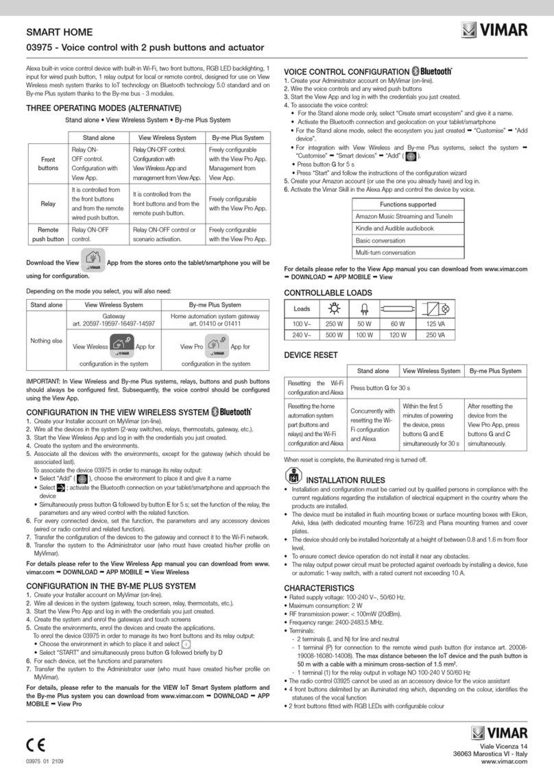
Vimar 03975 User manual

Vimar
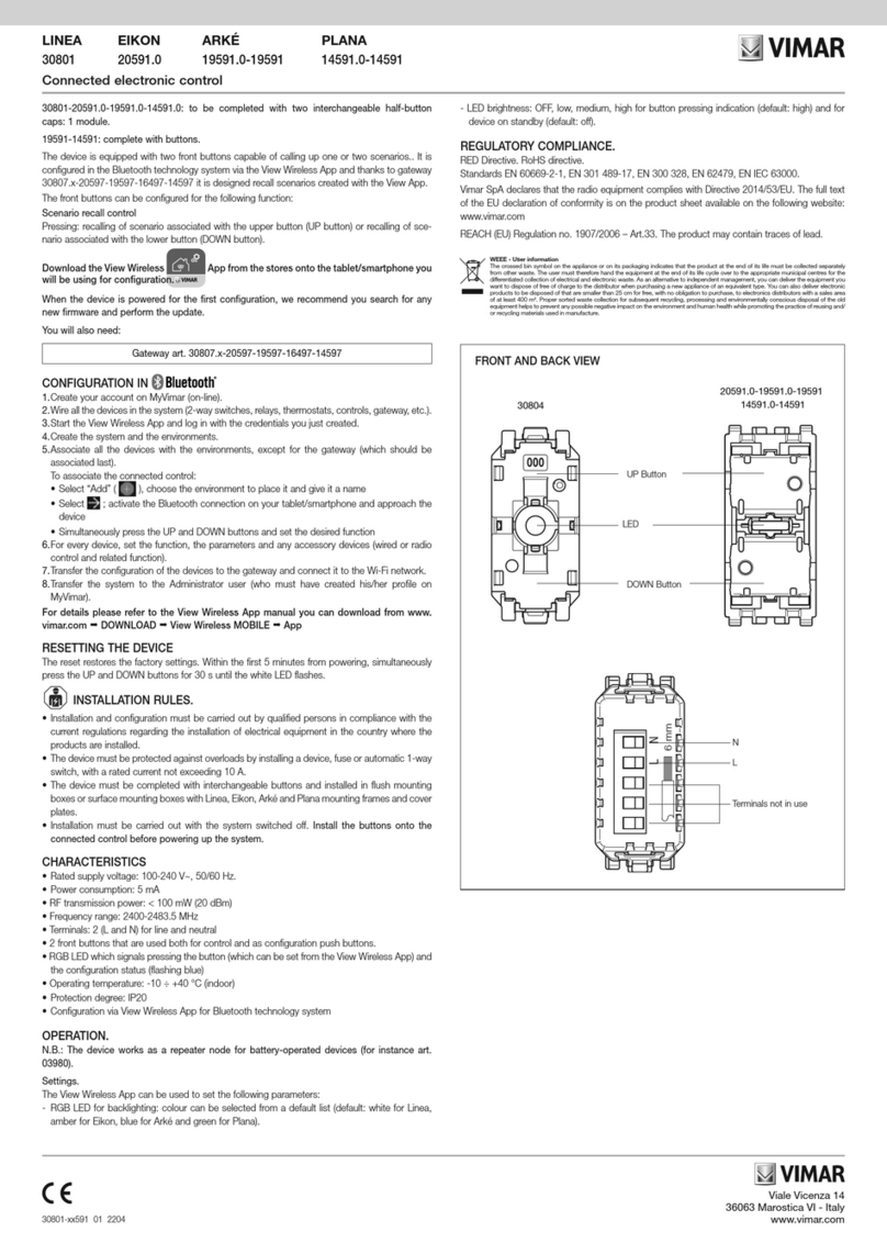
Vimar LINEA 30801 User manual

Vimar
Vimar BY-ME User manual

Vimar
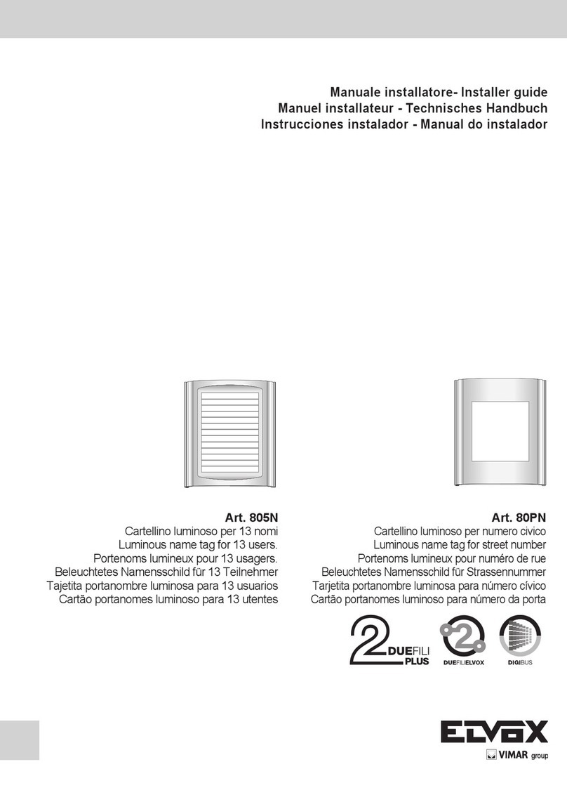
Vimar Elvox 805N Assembly instructions

Vimar
Vimar BY-ME PLUS 32041 Series User manual

Vimar
Vimar SMART HOME 03975 User manual

Vimar
Vimar SMART HOME 30815 Series User manual

Vimar
Vimar BY-ME PLUS 32031.G User manual

Vimar
Vimar BY-ME User manual

Vimar
Vimar 00801 User manual