Heatstore Aqua-Power User manual

IMPORTANT:
This booklet should be left with the user after
installation and demonstration
WARNING:
Under no circumstances should this unit be connected
to the mains cold water supply
Thermostatic Power Shower Unit
Installation and User Guide

2
CONTENTS
If you experience any difficulty with the installation or operation of your new
shower, thenplease refer to the “What to do if things go wrong” section in this
manual before contacting us.
Thank you for purchasing a quality Heatstore “Aqua-Power” Power Shower manufactured in England.
To enjoy your new shower at its best, please take time to read this manual thoroughly to
familiarise yourself with all instructions, BEFORE beginning installation.
1. Your shower has been designed for convenience, economy and safety of use, provided that it is
installed, used and maintained in good working order and in accordance with our instructions and
recommendations.
2. All wiring and installation must be supervised by a suitably qualified person.
3. THIS APPLIANCE MUST BE EARTHED.
4. The Heatstore “Aqua-Power” power shower isdesigned to boost the flow of stored domestic
water, which is gravity fed from astatic cold water cistern and hot water cylinder.
Under no circumstances shouldthis unit be connected directly to the mains cold or
hot water supplies.
5. The cold water cistern should have a minimum capacity of114 litres
(25 gallons).
There must be a minimum headof water of 8cm (3”) and a maximum head of 10m
(33ft)
between the bottom of the cold water cistern and the top of the shower unit.
Under no circumstances shouldany ofthepipeworksupplying theshowerunit
rise abovethelevelofthebottomofthecold water cistern.
6. The Heatstore “Aqua-Power” power shower incorporates a motorthat is designed for intermittent
use, and ther
efore, should NOT be used continuously for long periods of time.
The maximum length of time for any shower should not exceed 15 minutes.
A rest period of 45 minutes is thenrequired to allow the motor to cool down.
7. The installation must be in accordance with the current edition of BS.7671 (the “IEE Wiring
Regulations”) and “Part P” of the “Building Regulations” in force at the time of installation.
Installations outside England and Wales must also conform to any local regulations in effect.
This appliance is intended to be permanently connected to the fixed electrical wiring of the mains
supply with its own dedicated supply.
8. This appliance must NOT be fitted where it may be subjected to freezing conditions
9. DO NOT switch the appliance on if you suspect it of being frozen.
Wait until you are sure it has thawed out.
10. Isolate the mains electrical and water supply before removing the front cover of the appliance.
Section
Important Safety Information . . . . . . . . . . . . . . . . . . . . . . . . . . . . . . . . . . . . . . . .
How to install your “Aqua-Power” Shower . . . . . . . . . . . . . . . . . . . . . . . . . . . . . .
How to use your “Aqua-Power” Shower . . . . . . . . . . . . . . . . . . . . . . . . . . . . . . . .
How to maintain your “Aqua-Power” Shower . . . . . . . . . . . . . . . . . . . . . . . . . . . . .
What to do if things go wrong (1) Self Help . . . . . . . . . . . . . . . . . . . . . . . . . . . . . .
What to do if things go wrong (2) Professional Service . . . . . . . . . . . . . . . . . . . . . . .
Heatstore After Sales Service . . . . . . . . . . . . . . . . . . . . . . . . . . . . . . . . . . . . . . . . .
Filters Removal and Refitting . . . . . . . . . . . . . . . . . . . . . . . . . . . . . . . . . . . . . . . . . .
Assembly of Accessories . . . . . . . . . . . . . . . . . . . . . . . . . . . . . . . . . . . . . . . . . . . . .
Guarantee and Contact Details . . . . . . . . . . . . . . . . . . . . . . . . . . . . . . . . . . . . . . . .
Page
2
3
6
9
10
10
11
11
11
12
IMPORTANT SAFETY INFORMATION

3
WARNING: ALL WIRING AND INSTALLATION MUST BE SUPERVISED BY A SUITABLY
QUALIFIED PERSON.
WARNING: DO NOT INSTALL THIS SHOWER WHERE IT MAY BE SUBJECTED TO
FREEZING CONDITIONS
We recommend that the installation is done inthe following sequence.
a. Fixing the shower to the wall b. Plumbing c. Electrical connections d. Commissioning
a. FIXING THE SHOWER TO THE WALL
The Heatstore “Aqua-Power” power shower is fitted with a motor and some mechanical
noise can be expected when in use. The type of wall structure will affect the noise levels.
Solid walls will provide quieter operation than panel or stud walls.
1. Position the riser rail at a convenient height for the majority of
users as detailed in Diagram 1 and mark its position.
2. Position the unit so that the top of the unit is horizontaland that
all controls can be comfortably reached whilst the shower is
being used.
Ensure correct orientation of the shower unit ie: mounted as
shown in Diagram 1.
Choose a flat piece of wall to avoid the possibility of distorting the
backplate thus making the front cover a poorfit.
3. Adjust the position to get the most convenient arrangement
taking the following into account.
•The unit must not be mounted in the direct spray from
the handset.
4. Fix the riser rail with screws provided.
The fixing holes at the base of the brackets will be revealed by removing the plastic fronts.
Assemble as shown in Diagram 13.
5. Decide the position of the electrical cable into the unit.
If top or bottom entry is chosen, cut away the walls in the backplate as shown in Diagram 2.
6. Decide the position of entry of the cold waterpipes into the unit.
If top or bottom entry is chosen, carefully cut awaythe relevant walls of the backplate as shown
in Diagram 2.
If bottom entry is chosen,
refer to note 9 in the
plumbing section.
HOW TO INSTALL YOUR AQUA-POWER SHOWER

4
7. If you have not yet done so, remove the front cover assembly by undoing the retaining screws at
the top and bottom of the unit. Remove Temperature Control Knob “B” Cap (see Diagram 10) by
levering out carefully with a small flat bladed screwdriver and remove the small fixing screw as
shown in Diagram 3.
Your shower is provided with 4 fixing
positions in the backplate (Diagram 11).
The top-fixing holes are “key-hole” slots
and the most convenient should be
marked and drilled first.
Tighten top screw withhead protruding
about 10mm from the wall and hook
the backplate over the screw head.
This allows for correct and accurate
alignment of your shower before
marking and fixing the bottom position.
You may not wish to tighten up both screws at this stage as the holes are elongated to allow for
adjustment after otherconnections have taken place.
b. PLUMBING
WARNING: UNDER NO CIRCUMSTANCES SHOULD THIS UNIT BE CONNECTED TO THE
MAINS COLD WATER SUPPLY.
The unit must be connected to a cold water supply gravity fed froma static cold water cistern with
a minimum capacity of114 litres (25 gallons).
There must be a minimum head of water of8cm (3”) and a maximum head of 10m (33ft).
It is strongly advised to install the shower unit using an independent supply from the cold water
storage cistern and hot water cylinder.
The shower would be totally unaffected by the other draw off points elsewhere in the system and
thus the pressure and temperature will remain more stable.
Therefore, the cold water supply should be taken directly from the cold water cistern and the hot
water supply should betaken from the hot water cylinder via an Essex or Surrey Flange (Diagram 4)
Under no circumstances should any of the pipework supplying the shower unit rise above the level of
the bottom ofthe cold water cistern.
Before connecting the pipework to the shower ensure that the pipework is flushed out.
1. Surrey Flange (Top entry cylinder flange) Fitting Instructions.
The hot connection to the shower unit can betaken directly from the hot cylinder using a Surrey
Flange. Diagram 4 shows how this flange should be fitted.
2.
Essex Flange (Side entry cylinder flange) Fitting Instructions.
Alternatively, the hot connection to the shower can be taken directly from the hot cylinder using
an Essex cylinder flange and extension pipe. Diagram 4 shows how this flange should be fitted.
Connecting direct to the side of the cylinder is not recommended where a top entry
immersion heater is fitted.
3. The hot connection can also be taken from the hot supply to other outlets as in Diagram 5.
The connection must be made below the ventilation tee.
4. The thermostat on thehot water cylinder should ideally
be set at 60°C.
The maximum permissible inlet temperature is 65°C.

5
5. In all cases a dedicated cold water supply should be taken from the cold water cistern to the
shower unit.
The connection in the cistern should be made below the level of the cold water feed to the hot
water cylinder.
The connection should also be on the opposite side of the cistern to the float valve.
This will prevent air being sucked into the pump chamber.
6. It is recommended that isolating valves are fitted between the cold water storage cistern and the
shower unit and between the hot water cylinder and the shower unit (Diagrams 4 & 5).
This will allow the unit to be serviced or exchanged without turning off the cold water at the
water stop valve and draining the cold water cistern.

6
7. Ø15mm copper pipe should be used.
Ensure all burrs have been removed from the
pipes before inserting into the push fit inlet ports.
Diagram 7 illustrates the correct procedure for inserting
and removing the pipes from the inlet ports.
Take care to line up the inlet pipe correctly with the inlet
port to avoid straining the internal “O”-Ring seal.
DO NOT use solder fittings within 300mm of plastic
fittings.
DO NOT insert fingers into the push-
fit inlet ports.
Doing so could result in injury
8. To maintain the optimum performance, the pipe runs
should be kept as short as possible, using sweeping bends
rather than right angles or restrictive fittings.
9. If bottom entry has been chosen, the inlet port must be
rotated through 180° into the required position.
To do this, unscrew the combined inlet elbow (Diagram 8)
and remove the side section from the shower unit.
Remove combined elbow and rotate forbottom entry.
Slide back into positionensuring that the “O”-Ring seals
are correctly in place. Please note HOT and COLD marking.
Replace the side section and tighten 2 screws in elbow to lock into position.
10.With isolating valve connected,
flush the pipe work through to
remove any particles etc, before
making the final connection to the shower.
Blockage in the water ways (particularly
the handset and filters) will prevent
the shower unit working properly.
Note: You may be charged for a service
call if it is due to incorrect installation.
c) ELECTRICAL
WARNING: THIS SHOWER MUST BE EARTHED.
1. The electrical installation must be in accordance with the current BS.7671 (IEE Wiring
Regulations) and “Part P” of the Building Regulations and/orlocal regulations
2. A means for disconnection in all poles must be incorporated in the fixed wiring in accordance
with the wiring rules. We recommend a ceiling switch mounted in a convenient position.
3. For additional safety, it is recommended that a RDC be used.
4. We recommend using 1.0mm² Twin and Earth cable
for this application.
Connect the mains cable in to the terminal block,
ensuring that all power is switched off
before connecting to the mains supply.
Recommended order:-
i) Strip back wire approximately 6.0mm.
ii) Ensure wires are secure in the correct
terminal block holes.
iii) Ensure that the mains cable is securely
clamped in the cable clamp provided on the backplate.

7
IMPORTANT WARNINGS!
THIS APPLIANCE IS NOT INTENDED FORUSE BY PERSONS (INCLUDING CHILDREN AND
THE INFIRM) WITH REDUCED PHYSICAL,SENSORY OR MENTAL CAPABILITIES,
OR LACK OF EXPERIENCE AND KNOWLEDGE, UNLESS THEY HAVE BEEN GIVEN
SUPERVISION OR INSTRUCTION CONCERNING USE OF THE APPLIANCE
BY A PERSON RESPONSIBLE FOR THEIR SAFETY.
CHILDREN SHOULDBE SUPERVISED TO ENSURE THAT THEY
DO NOT PLAY WITH THE APPLIANCE.
d) FINAL INSTALLATION PROCEDURE AND COMMISSIONING
WARNING: DO NOT SWITCH ONTHE ELECTRICITY SUPPLY UNTIL THE FOLLOWING
PROCEDURE HAS BEEN COMPLETED. FAILURE TO DO SOCOULD CAUSE
THE PUMP TO RUN DRY AND INVALIDATE THE GUARANTEE
1. Fit the hose to the shower unit outlet first without the handset to flush out any remaining debris.
Ensure that the water isolating valves are fully open and that the hose is directed to waste.
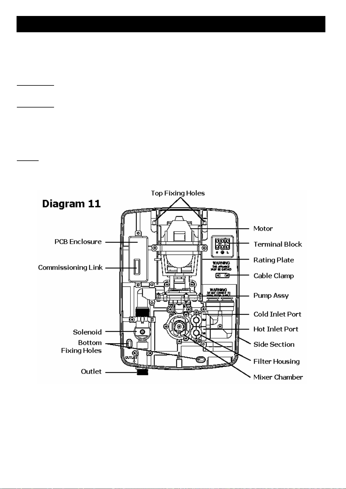
2. The shower unit is factory set in the commissioning mode. A commissioning link is connected to
the PCB (Diagram 11), which opens the solenoid without switching on the motor.
This allows water to flow through the pump, thus ensuring that all air is removed.
The cover is not required to be fitted at this stage but be aware of live parts when the
electricity is temporarily switched on.
3. Switch on electricity supply. After a few moments water should drip from the hose.
It may be necessary to hang the hose from the shower unit whilst priming, especially
if the head of water is minimal. This will speed upthe priming process.
When water drips through the hose at a constant rate, stop flow of water by switching off the
electricity supply.
Ensure electricity is switched off.
Remove PCB Commissioning Link and replacewith the connectorattached to the front cover
start/stop/flow control switch.
Store commissioning link ina safe place for future use.
4. Ensure side section is on place (Diagram 11).
Refit cover using 3 fixing screws and attach handset to shower hose.
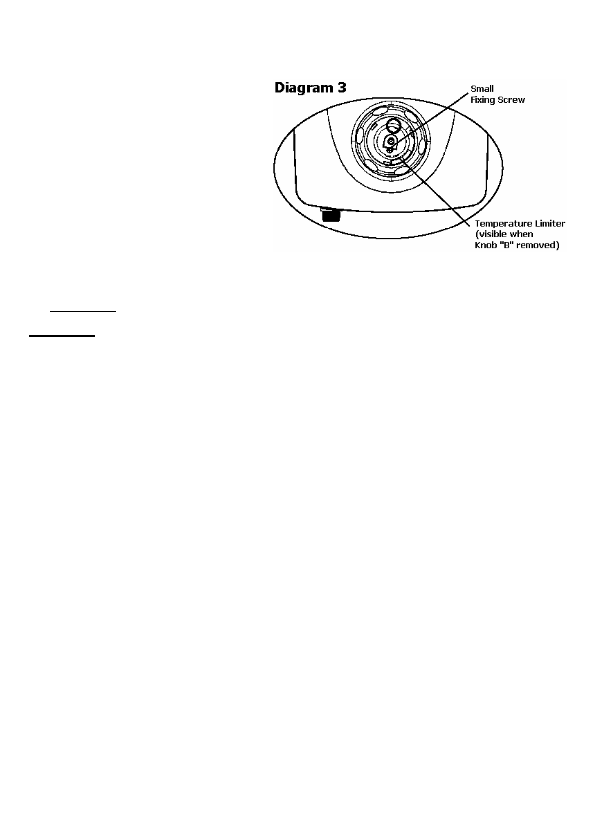
5. A temperature limiter is provided so that the maximum working temperature can be set.
The limiter is factory set, but can be adjusted depending on incoming water conditions.
The limiter is visible when Temperature Control Knob “B” is removed (Diagram 3).
Gently prise away the limiter from the front cover and rotate to new position.
Rotate clockwise for a cooler stop position and anti-clockwise for a warmer stop position.
Ensure that the limiter is pressed firmly home. Re-assemble Temperature Control Knob “B”over
the drive on the mixer unit and fix into place with a screw.
Check that its movement is restricted sufficiently. Also check operation of temperature over-ride
button (Diagram 10). Re-fit controlknob cap by positioning correctly and pressing firmly home.
6. Switch on the electricity supply and then operate the shower as shown on page 8 and check:-
a. The shower switched on when the flow control knob “A” is rotated and that flow is adjustable.
b. Temperature can be adjusted by knob “B”and the limiter position issatisfactorily ie: NOT hot
enough to scald.
c. Operation of over-ride button allows the temperature limiter positionto be overridden.
d. Check again for leaks.
e. That the motor turns off and water stops flowing in the STOP position of knob “A”.
7. PLEASE DEMONSTRATE OPERATION TO USERS

8
IF WATER IS TOO COLD
Turn knob “B” anti-clockwise to a lower
number on the temperature scale and
continue turning clockwise until you get the
water temperature of your liking.
Wait 10 seconds after each adjustment
for the water temperature to stabilise.
The final adjustment may be anywhere on
the scale.
IF WATER IS TOO HOT
Turn knob “B” clockwise to a lower
number on the temperature scale and
continue turning anti-clockwise until you get
the water temperatureof your liking.
Wait 10 seconds after each adjustment for
the water temperatureto stabilise.
The final adjustment may be anywhere on the
scale.
1. Ensure the electricity and water are turned on to the unit.
2. Your shower has 2 control knobs (Diagram 10).
Knob “A” controls the Start/Stop operation and
the water flow rate of the shower unit.
Knob “B” controls the temperature of water and
also incorporates a temperature limiter.
3. To start the shower turn knob “A” clockwise
from the STOP position.
Adjust the control until a satisfactory flow rate
is achieved.
For maximum flow, turn knob “A” fully clockwise.
4. To adjust the temperature, turn knob “B”
clockwise
to a lower number on the temperature
scale for a cooler shower and anti-clockwise
to a
higher number on the temperature scale for a
warmer shower.
Please allow time for the hot water to reach the shower unit from the storage cylinder.
Note: It is recommended that you test the water temperature with your hand before
stepping under the water spray, even if the shower has justbeenused.
5. To stop the shower, turn knob “A” fully anti-clockwise to the “Stop”
position.
6. Switch off the electricity at the ceiling switch or local isolator.
7. As a safety feature, a temperature limiter is provided so that the maximum working temperature
of the shower unit canbe set.
The limiter is factory set, but can be adjusted to suit on site conditions. If the position of the
limiter requires adjustment please refer to the section in the commissioning procedure (page 7).
8. To override the STOP position of the limiter, press the button on knob “B” and continue turning
knob “B” anti-clockwise to a higher number on the temperature scale until the desired
temperature is reached.
9. If the temperature limiter has been overridden, knob “B” MUST always be returned to the
normal temperature range when the shower is switched off. To do this, simply turn knob “B”
clockwise past the limier position. The buttondoes not need to be depressed when returning to
the normal temperature range.
10. There are a number ofdefined spray setting provided by the handset.
The handset spray plate can be turned in either direction to change the spray pattern.
HOW TO USE YOUR AQUA-POWER SHOWER

9
HOW TO MAINTAIN YOUR AQUA-POWER SHOWER
It is recommended that the shower unit and hose etc. be cleaned using a soft cloth and that the use
of abrasive or solvent based cleaning fluid be avoided, especially onany plated finishes.
We recommend that before any cleaning, the isolating switch be turned off, thus avoiding
accidentally switching on the shower.
WARNING:
YOU MUST REGULARLY INSPECT THE SHOWER HOSE FOR WEAR AND DAMAGE.
REPLACE IF NECESSARY, OR EVERY TWO YEARS, WITH AN APPROVED PART.
WARNING: IN ORDER TO MAINTAIN THE PERFORMANCE OF YOUR SHOWER,
YOU MUST CLEAN THE SHOWER HANDSET REGULARLY
All water contains particles of lime-scale, which build up in the shower handset and
unit reducing the performance.
It is therefore important to clean the shower handset by soaking in proprietary lime-scale remover
ensuring it is rinsed thoroughly before use.
NOTE: After use it is normal for some waterto drip from the shower handset for
a few moments. This inhibits scale build-up over prolonged use.

10
WHAT TO DO IF THINGS GO WRONG (1)
WHAT TO DO IF THINGS GO WRONG (2)
SELF HELP
If the shower is not working satisfactorily, make the following checks before calling out the installer.
Any one of these adjustments could restore the performance.
System will not operate Check that the mains electricity supply is switched on.
Pump operates but no
water is delivered Check water is available to both ports, andthat all isolating valves are open.
Check for an air-lock in the pump chamber.
Water too COLD Turn Temperature Control Knob “B” anti-clockwise to a higher number on
the temperature scale (Diagram 10).
Check that hot water is available in the hot water cylinder. The ideal
thermostat setting for the hot water storage cylinder is 60°C (140°F).
Check that the HOT water isolating valve is open.
If possible, reposition temperature limiting device so that more movement
of knob “B” is allowed.
Water too HOT Turn Temperature Control Knob “B” clockwise to a lower number on the
temperature scale (Diagram 10).
Check that the COLD water isolating valve is open.
Spray pattern poor Clean the shower handset. Select an outer/inner spray pattern.
PROFESSIONAL SERVICE
If the previous “Self Help” checks fail to restore the performance, you should seek professional help.
The person who installed the shower is probably the best one to investigate and correct it and is
certainly the person to contact if you have had a problem in the guarantee period.
The following additional checklist is provided for the benefit of the qualified service person.
WARNING: SWITCH OFF THE ELECTRICITY AT THE LOCAL ISOLATOR
BEFORE REMOVING THE COVER TO MAKE CHECKS
Pump operates but no
water is delivered Check the inlet connections to the mixing chamber are piped correctly.
Check that the shower and all pipe work are sited below the level of the
cold water tank and that it is fully primed and is therefore not air-locked.
(See commissioning procedure on page 7).
Pump operates when
motor is switched off Check for faulty potentiometer switch, located under knob “A” inside
front cover.
Switch should be open circuit when turned fully anti-clockwise.
Water too hot Blockage in filter causing obstruction in water supply.
Check and clean (see page 11).
Water too cold
Blockage in filter causing obstruction in water supply.
Check and clean (see page 11).
Poor temperature
adjustment Check the hot and cold water supplies are delivered to the correct ports.
Check that water is supplied to the shower unit at balanced pressures
(ie Hot and Cold waterare supplied from the same header tank).
Ensure cold water supply is not taken from mains.
Unit does not prime Check that the shower and all pipe work are sited below the level of the
cold water tank.
Poor flow rate Check for any restrictions in the Ø15mm supply (reduced diameters even
for short distances).
Check that pressure is not being lost to other services in the dwelling.
Check filter for obstructions in the water supply and clean if necessary.

11
HEATSTORE AFTER SALES SERVICE
We offer a technical advisory service to installers and other customers with problems in the field.
RING: “0117 923 5375” or E-MAIL: “enquiries.heatstore@adivision.co.uk”
Remember to quote the exact type of shower, as written on the front of the shower and onthis
leaflet. The model and serial number are located on the bottom face of the shower.
Make a note of those numbers here, and be sure to quote them if you call for advice.
Model Number: _ _ _ _ _ _ _ _ _ _ _ _ _ Serial Number: _ _ _ _ _ _ _ _ _ _ _ _ _ _
Note: You may be charged for aservice call if you do not have the serial number.
Inlet filters have been incorporated in the design of the Heatstore “Aqua-Power” power shower which
protects the internal mechanisms of the shower unit and the handset. If the performance of the
shower deteriorates (ie flow reduction occurs) then it may be necessary to clean the filters.
WARNING:
SWITCH OFF THE ELECTRICITY AT THE LOCAL ISOLATOR
BEFORE REMOVING THE COVER TO MAKE CHECKS
Remove the shower cover as detailed in note 7 on page 4.
The cover will be connected to the PCB via a floating lead.
Carefully pull the lead from the PCB.
DO NOT let the front cover hang by the lead
as this will damage the PCB.
The filters are positioned in the inlet housing (Diagram 12).
Remove 2 fixing screws and the filter cap from the
housing and remove both filters. Wash thoroughly
under running water and replace in housing.
Ensure that both “O”-Ring seals are fitted to
the filter cap and reassemble cap using
2 fixing screws.
It maybe necessary to re-prime the shower
unit after the filters have been cleaned.
Please refer to the commissioning procedure (see page 7).
Refit the front cover and Temperature Control Knob “B” as described in the commissioning procedure
FILTER REMOVAL AND REFITTING
ASSEMBLY OF ACCESSORIES

12
HEATSTORE & ADDVENT
VICTORIA ROAD, AVONMOUTH, BRISTOL, BS11 9DB
WEBSITE: www.heatstore.co.uk
We offer a technical advisory service to installers and other customers with problems in
the field. RING: “0117 923 5375”or E-MAIL: “enquiries.heatstore@adivision.co.uk”
GUARANTEE AND CONTACT DETAILS
(
A4
Leaflet No.55
9
-
2333
-
02B
Table of contents
Other Heatstore Bathroom Fixture manuals
Popular Bathroom Fixture manuals by other brands

Graff
Graff AMETIS G-8760 installation instructions

brondell
brondell PureSpa PS90 quick start guide

Hans Grohe
Hans Grohe Talis Classic 14145 Series manual

FM Mattsson
FM Mattsson 9000E Tronic instructions

Ergonomic products
Ergonomic products N3A Series Specification and installation guide

Hans Grohe
Hans Grohe Crometta 85 Multi 28563000 Assembly instructions