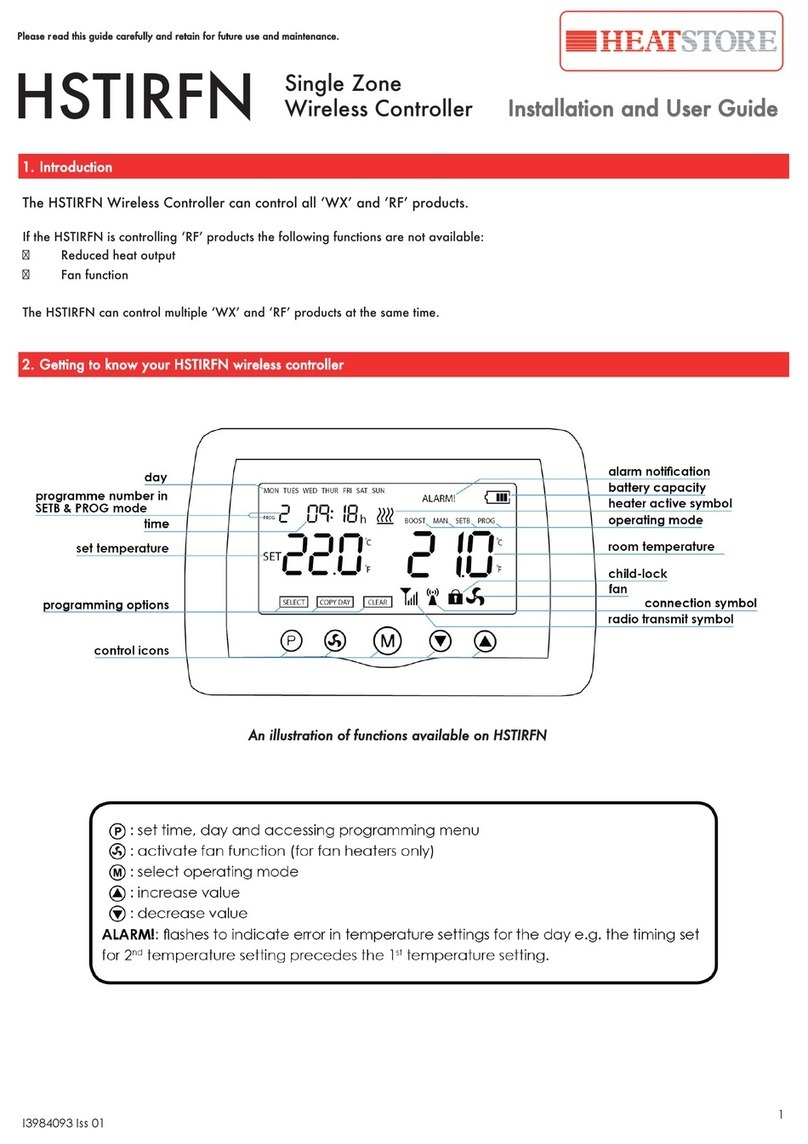
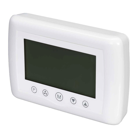
Heatstore HSTIRF Use and maintenance manual

Installation & Control Guide for HSTIRF
Wireless Controller
HSTIRF CONTROLLER
All electrical appliances produced for the Company are guaranteed for one year against faulty material or
workmanship. This applies only if the appliance has been used for purposes in accordance with the instructions
provided and has not been connected to an unsuitable electricity supply, or subject to misuse, neglect, damage
or modified or repaired by any person not authorised by us. This guarantee is offered to you as an extra benefit and
does not affect your legal rights.
The correct electricity supply voltage is shown on the rating label attached to the appliance.
Reasonable care has been taken to ensure that this guide is accurate at the time of printing. In the interests
of progress the Company reserve the right to vary specifications from time to time without notice.
Heatstore,
Unit 12, Access 18, Bristol BS11 8HT
Tel: 0117 9235375
Fax: 0117 9235374
Web: www.heatstore.co.uk

2
The HSTIRF controller can control an unlimited
number of heaters. The controller has 4
operating modes. When a button is pressed,
the LCD backlight will turn on. It will stay ON
for approximately 10 seconds. The display
shows time, day, room temperature and the
controller status.
Please read this guide carefully and retain for future use and maintenance purposes.
Installation and User Guide
Mode
Temp
ProgTime
SET TIME SET PROGRAMME
SET TEMPERATURE MODE SELECTION:
BOOST, COMF,
SETB, T
BOOST - 15 minutes boost to a set
temperature limit.
After 15 minutes, heater will revert back
to the previous setting.
COMF
Heater maintains a set comfort
temperature.
Temperature range 16°C - 35°C.
SETB
Heater can be set to stand by, frost
protection or maintaining a setback
temperature.
Temperature range 4°C - 16°C, 4°C is frost
protection and symbol ‘- - -’ is for stand
by mode.
T - Automatic mode
Option for 24 hour timer or 7 day
programmed operation.
Heater is operating on the pre set Comfort
and Setback periods.
Up to 3 programmes per day.
Press and hold the TIME button for 5
seconds.
Hours are flashing - use TEMP and
MODE buttons to set hours.
Press TIME button
Minutes are flashing - use TEMP and
MODE buttons to set Minutes.
Press TIME button
Day is flashing - use TEMP and MODE
buttons to set Day.
Once you are happy with the
settings, press ‘Time’ to return to main
screen.
Mode
Temp
ProgTime
Setting the Time and Day
Temp on Display= Room Temp
To change mode, press MODE.
Heat symbol = Heat is on
To display temperature on display, press TEMP.
To display time on display, press TIME.
Mode
Locking / Unlocking the buttons
Press and hold the TIME & TEMP buttons for 5
seconds or until you hear a noise.
HSTIRF
Wireless Controller
1. Getting to know your HSVTRF wireless controller

3
Press PROG button
Minutes are flashing - use TEMP and MODE
buttons to set Minutes.
Press PROG button
Now you are setting time for the end of the
1st heating period.
From now the heater will maintain SETB
temperature.
PROG 1 SETB
Hours are flashing - use TEMP and MODE
buttons to set hours.
Press PROG button
Now you are setting time for the beginning
of the 2nd heating period.
This pattern continues, the PROG button
advances to the next setting and TEMP and
MODE are used to adjust the hours and minutes.
If a heating period is not required set the time to
- - : - - and this will make the period inactive.
When you reach the end of the 3rd heating
period of the day and press the PROG button the
program is saved to memory. The display returns
to either the main screen or the day select
screen. If the display times out during
programming then the program will not be
saved.
Repeat this process for whichever days you wish
to set a program for.
Once you set every time, press PROG to return to
main screen. Alternatively, hold PROG for 5
seconds to exit programming.
0 1 2 3 4 5 6 7 8 9 10 11 12 13 14 15 16 17 18 19 20 21 22 23 24
HOUR
EXAMPLE OF TIME SCHEDULE FOR ONE DAY WITH 2 HEATING
PERIODS
COMF TEMPERATURE
SETB TEMPERATURE
PROG 1
ON
PROG
2 ON
PROG 1
OFF
PROG 2
OFF
Setting Temperature Comfort,
Setback and Boost periods
The comfort and setback temperatures are set
during the same procedure. The comfort is set first,
followed by the setback. Make sure the mode is
set to COMF, SETB or T mode.
Press TEMP button
The display now shows the COMF icon and
the set temperature for COMF mode is
flashing.
Within 2 seconds press TEMP or MODE
buttons to set required temperature for
Comfort mode. The range is 16°C - 35°C (ON
period).
Press PROG button
The display now shows the SETB icon and the
set temperature for SETB mode is flashing.
Within 2 seconds press TEMP or MODE
buttons to set temperature for Setback
mode.
The range is ‘- - -’, 4°C - 16°C (OFF period)
‘- - -’ means heating OFF.
To set a temperature limit for BOOST mode:
Press MODE button
The controller is now in BOOST mode.
Wait until the display shows the remaining
time.
Press TEMP button
The display is showing the BOOST icon and
the set temperature limit for BOOST mode is
flashing. Within 2 seconds press TEMP or
MODE buttons to set temperature limit for
BOOST mode. The range is 25°C - 35°C.
Setting up a programmed
Time schedule
Hold PROG button for 5 seconds
Select 24 hour timer or 7 day timer - use
TEMP and MODE buttons.
Press the PROG button
Day is flashing - use TEMP and MODE
buttons to select day you want to set the
time schedule for.
Press PROG button
Now you are setting time for the
beginning of the 1st heating period.
From now the heater will maintain COMF
temperature.
PROG 1 COMF
Hours are flashing - use TEMP and MODE
buttons to set hours.

4
Do NOT handle the appliance with wet hands.
Do NOT use the appliance in workshops or rooms where excessive dust is generated or present.
Ensure that nothing is pushed into any aperture of this controller.
Do NOT cover or restrict any aperture Do NOT use the appliance if damaged.
Do NOT leave the appliance unattended where young children are present.
If used in a bathroom, the heater is to be installed so that it cannot be touched by a person in the bath or
shower.
Operating temperature range -10 to +40ºC.
N
L
Mains Connection
230/240V AC 50Hz
+
-
12V DC
Installation
The controller is designed to fit onto most single gang back boxes. Please note the pattress screws must be oriented
vertically. When a metal box is used this must be earthed. The controller can be powered by either mains 240VAC
50Hz or 12VDC. The power consumption is less than 1W. Do not connect mains voltage to 12V terminals, this will
damage the controller. The maximum size wire that can be used is 1mm2, this can be twin and earth or standard
flex . Do not over-tighten the connector screws. Take care not to damage the components when connecting the
cables.
Connection to the Mains supply
For the mains power, connect L and N wires to the connectors marked as L and N.
Electrical installation should be carried out by a competent installer, preferably registered with NICEIC (National
Inspection Council for Electrical Installation Contracting) in accordance with the 17 edition of the IEE Wiring
Regulations, (BS.7671), and any relevant Local Authority Bye-Laws. This heater is fitted with a 3-core mains supply
cable and should be permanently connected to the electricity supply via a double pole switch having 3mm gap
on each pole. A switched Fused Connection unit to BS.1363. Part 4 is a recommended mains supply connection
accessory to ensure compliance with safety requirements applicable to fixed-wiring installation.
Connection to 12V
Powering the controller with 12Vdc allows the controller to be installed in a zone 2 area, however, the installation
must comply with the Separated Extra Low Voltage (SELV) requirements. When powered by 12VDC, please ensure
that the power supply is suitable for 12V 0.1A. For 12VDC power connect positive wire to terminal marked +12V and
negative to terminal marked –12V.
Please note: A 12Vdc power supply does not come with this controller, however, a standard 12Vdc constant voltage LED
driver could be used.
Warnings
Pairing with heaters
In order to pair your appliance with the controller you must:
Turn power to the appliance ON.
Within 20 seconds, press and hold the TIME and PROG buttons on the controller for 2 seconds.
Press Boost button. You should see the heat symbol on the display. If the pairing was successful, the appliance
should emit heat. It can take up to 4 seconds. If the heating symbol isn’t shown on the display, ensure that the
temperature for BOOST mode is set to 35°C.
Memory backup battery
(the controller will remember all settings including
time for 1 year after disconnected from power)
Other Heatstore Controllers manuals
Popular Controllers manuals by other brands

Cooper
Cooper CEAG GHG 635 GHG 635 operating instructions

Oxford Instrucments
Oxford Instrucments ITC503 Operator's handbook

Ponast
Ponast Sigmatek Instructions for use and installation

VS LIGHTING SOLUTIONS
VS LIGHTING SOLUTIONS Blu2Light MultiSensor XS manual

Siemens
Siemens FC18 Series operating manual

Mircom
Mircom TX3-BBCX-4W Assembly