Heftee 250 User manual
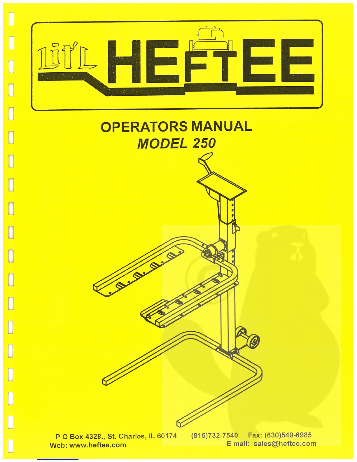
OPERATORS
MANUAL
ODEL
250
P
0
Box
4328.,
St.
Charles,
IL
60174
[j
Web:
www.heftee.com
(815)732-7540
Fax:
(630)549-6985
E
mail:

1
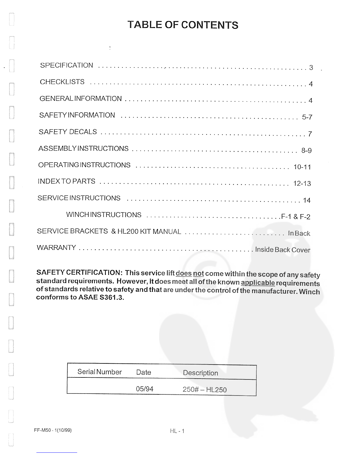
TABLE
OF
CONTENTS
SAFETY
CERTIFICATJON:
This service
lift
does
~
come
within
the
scope
of
any
safety
standard
requirements.
However,
It
does
meet
all
of
the known
~pplicable
requirements
of
standards
relative
to
safety
and
that
are
underthe
control
of
the
manufacturer. Winch
conforms
to
ASAE
S361
.3.
FF-M50
-
1(10/99)
Serial
Number
Date
05/94
Description
250#
—
HL250
SPECIFICATION
3
CHECKLISTS
4
GENERAL
INFORMATION
4
SAFETYINFORMATION
5-7
SAFETYDECALS
ASSEMBLYINSTRUCTIONS
8-9
OPERATINGINSTRUCTIONS
io-ii
INDEXTOPARTS
12-13
SERVICE
JNSTRUCTIONS
14
WINCHINSTRUCTIONS
F-1&F-2
SERVICE
BRACKETS
&
HL200
KIT
MANUAL
In
Back
WARRANTY
Inside
Back
Cover
HL-1


SPECIFICATIONS
Lit1~.
HEFTEE
RATEDLIFTCAPACITY
250#
91
Kg
OVERALLWIDTH
maximum:
37”
86
cm
OVERALL
HEIGHT(MANUALWINCH)
6111
55CM
DEPTH
-
FRONT
TO
BACK (APPROX)
48”
122CM
TREADWIDTHTOOUTSIDEQFWHEELS
maximum:
34”
86cm
TREAD
WIDTHTO
INSIDEOFWHEELS
minimum:
13”
33
cm
LIFT FRAME
WIDTH
ADJUSTABLE
BY
PINS
maximum:
37”
86
cm
LIFT
FRAME
WIDTH ADJUSTABLE
BYPINS miminum:
20”
51
cm
LIFT
FRAME
FORK
LENGTH
39”
86CM
LIFT
HEIGHTTO
BOTTOM
OFWHEELS
maximum:
49”
125
cm
TREAD
LENGTH
(BETWEEN
AXLECENTER
LINE)
maximum:
30”
76
cm
LIFTCABLE:
1!8”AIRCRAFT
32cm
DROP
SAFETY
CONTROL
SAFETY
LOCK:
each
1
Y2”
down
to
21”
height
2
TRANSPORT
WHEELS
-
USABLE
WHEN
UNIT
IS
TIPPED BACK 4”
10
cm
dia
SHIPPINGWEIGHT(BASIC
MACHINE)
155#
64
Kg
SHIPPINGBOXSIZE
1
BOX
53Y2X32X5Y2”
135X81
X
14cm
LOADTESTEDAT~
1000
Ibs
364Kg
INSTALLATION:
NONE
REQUIRED
FOR
STANDARD FLOOR
MODEL.
USES
SUPPORT
LEGS.
WINCHRATIO(EFFECTIVE)
.
APPROX.
1:10
WINCH
ACTION:
10
TURNS
TO
FULL
UP
(APPROXIMATELY).
WINCH
TYPE:
AUTOMATIC
BRAKE—HANDLE STOPS
WHEN
RELEASED,
EITHER
UPOR
DOWN.
NO
CHANGE
REQUIRED.JUSTCRANKUP,C’RANKDOWN.MEETSASAESAFETySTANDARDFORSAFETyWINCH
ASAE
S361,3
SAFETY
FOR PORTABLE
AGRICULTURAL
AUGER
CONVEYING
EQUIPMENT
WHICH
INCLUDESWINCH
REQUIREMENTS:
Patent
Pend
Ing
-
Subject
to
charige
without
notice.
FF-M50
-2
(Rev.
12/97;
3/04)
HL
-
3

Lît’L
HEFTEE
A
NEW
GENERATION
IN
SERWCE
SAFETY
AND
CONVENIENCE.
CHECK
LISTS
PRE-USE
CHECK
LIST
GENERAL
CHECK
LIST
BEFORE
EACH
USE
lnspect
the
Lit’L
HEF
TEEthoroughly
after
assembly
to
be
certain
that
it
is
set
up
properly. The following
~
Measure
and
be
sure
wheels
of
machine
are
checklist
is
a
reminder
of
points
to
inspect.
Check
centered
in
wheel cups before raising.
off
each
item
as
it
is
found
satisfactory
or
after
proper adjustment
is
made.
L1
On
heavy
loads,
be
sure
weight
is
centered
on
EJCheck
all
boits
to
make sure
that they
are
tight.
lift
as
much
as
practical.
NOTE:
See
assembly
instructions.
LJAlways
tie
machine
to
an
arm
on
EACH
side
LII
8e
sure
safety
lock
operates freely
and
snaps
before performing
any
work, rotating,
raising,
etc.
into
place
and
hooks
and
locks properly.
8e
sure
rotational
safety
lock
swings
into
lock
Check
all
bolts
to
make sure
that
they
are tight.
position
freely.
r::i
Be
sure winch cable
is
wrapped
evenly
and
secured
to
the
lift lug.
Also
be
sure
the
cable
is
free
of
kinks or
frayed
areas.
GENERAL
INFORMATION
The
purpose
ofthis
manual
is
to
assistthe
operator
in
MAl
NTE
NANCE
maintaining
and
operating
the
Lift
HEFTEE.
Read
it
carefully.
It
furnishes
information
and
instructions
Keep tie
downs
and
safety
locks
in
good
condition
that
will
help
you
achieve
years
of
dependable
and and
working
properly.
safe
performance.
These
operating
and
maintenance
instructions
have
been
compiled
from extensive
expe
rience
and
engineering
data.
The
illustrations
and
data used
in
this manual
were
current
at
the
time
of
printing.
But
due
to
possible
in-
line
production
changes
your
lift
may
vary slightly
in
detail.
HEFTEE
Industries
LLC
reserves
the
right
to
re-design
and
change
the
lift as
may
be
necessary
without
notification.
FF-M50
-4
(3/99)
HL-
4

TO
THE
OWNER:
Read
this
manual before
using
your
Lit’L
HEFTEE.
The
information
presented
will
prepare
you
to do
a
better,
safer
job.
Keep this
manual
handy
for
ready reference
and
training
of
future
users.
The
Lit’L
HEFTEE
you
have purchased
has
been
carefully
engineered
and
manufactured
to
provide
dependable
and
satisfactory
use.
Like
all
mechanical
products,
t
will
require
cleaning
and
upkeep.
Service
the
Lift
HEFTEE
as
specified. Observe
all
safety
information
in
this manual
and
safety decals
on
the
Lit’L
HEFTEE.
Use
onlygenuine
HEFTEE
service
parts.
Substitute
parts
will
void
the
warranty
and
may
not
meetstandards
required
for
safe
and
satisfactory
operation.
Record
the model
and
serial
number
of
your
Lift
HEFTEE.
Model:
_______________
Serial
Number:
(Located
on
the
slider
asy
of
Lift
HEFTEE
frame)
Throughout
this
manual, the
term
IMPORTANT
is
used
to
indicate
that failure
to
observe
can
cause
damage
to
equipment.
The terms
CAUTION,
WARN
ING,
and
DANGER
are
used
in
conjunction
with
the
Safety-Alert
Symbol,
(a
triangle
with
an
exclamation
mark),
to
indicate
the
degree
of
hazard
for
items
of
personal
safety.
SAFETY
TAKE
NOTE! THIS
SAFETYALERTSYMBOL
FOUNDTHROUGHOUTTHIS
MANUAL
IS
USED
TO
CALL
YOUR
ATTENTION
TO
THE
INSTRUCTIONS
INVOLVING YOUR
PERSONAL
SAFETYAND
THE
SAFETY
OF
OTHERS.
FAILURE
TO
FOLLOWTHESE
INSTRUCTIONS
CAN
RESULT
IN
INJURY
OR
DEATH.
THIS
SYMBOL MEANS
-ATTENTION!
-BECOME
ALERT!
-YOUR
SAFETY
IS
INVOLVED!
CAUTION
lndicates
a
potentially hazardous situation
that,
if
not
avoided,
may
result
in
minor
or
moderate
injury.
It
may
also
be
used
to alert
against
unsafe
practices.
WARN
ING
Indicates
a
potentially hazardous situation
that,
1f
not
avoided,
could
result
in
death
or
serious
injury,
and
includes hazards that
are
exposed
when
guards
are
removed.
It
may
also
be
used to
alert
against
unsafe practices.
DANGER
Indicates
an
imminently hazardous situation
that,
1f
not
avoided,
will
result
in
death
or
serious
injury.
This signal
word
is
to
be
limited
to
the
most
extreme situations
typically for
machine
components
which,
for
functional
purposes, cannot
be
guarded.
5/94(REVISED
11/96)
PATENTS
PENDING
HL-5

SAFETY
INFORMATION
The
Lît’L
HEFTEE
has
been
designed with every
possible
safety
provision
known,
except
a
careful
opera
tor,
but only
you
can
assure
proper
and safe
use.
TRAINING
OPERATIONALSAFETY
~
READ
this
manual
especially
the
safety
and
operating
instructions
before
using.
CAUTION
c~’
Do
not
allow
children
to
operate
or
play
on
In
addition
to
the
design
and
the
configuration
machine
and
do
not
allow
anyone
to
operate
without
of
equipment,
Hazard
control
and
accident
pre
proper instruction.
vention
are
dependent
upon
the
awareness,
con
cern,
prudence
and
proper
training
of
personnel
Ç~’
Allow
no
one
to be
on
or
under machine
while
involveci
in
the
operation,
transport,
mainte
raising
or
lowering or
operating
the
controls.
nance
and
storage
of
equipment.
~
Always
wear
safety glasses, safety
shoes
and
proper
clothing
for
the
job.
c~’
Never
use
drugs or
alcoholic beverages
when
operating
any mechanical
equipment
especially
the
HEFTEE.
~~‘Replace
any
decals
immediately
if
damaged.
Clean
area
for
decal
with
soap
and
water.
Remove
any
dirt,
grease
or
remnants
of
old
decal.
Re-apply
pressure
sensitive
decal
in
same
location.
~
Position
machine
carefully
with
all
wheels
cen
tered
in
wheel
cups before
raising.
On
heavy
loads
keep
weight
centered
as
much
as
feasible
and
close
in
to
mast.
cZ
Do
not
try
to
lift
over
250#
on
HL250.
1f
it
will not
easily
raise
the
bad,
it
is
too
heavy.
Do
not
try
to
lift
full
bad
on
end
of
arms.
Read
and
observe
all
safety
decals
on
the
Lift
HEFTEE.
ç~
Never
albow
anyone
on
the
equipment
or
under
equipment
when
raising,
bowering,
or
in
any
way
operating
control.
~
Always
bower
lift
onto
safety
locks
before
at
tempting
any
work
and
bower
to
fboor
before leaving.
c~’Tie
machine
securely
to
the
lift
arms
or
wheel
cups
on
both
sides before
attempting
any
repairs.
Use
straps
provided.
ç~’
Do
not
run
machine
engine
while
on
lift.
Discon
nect
spark
plug
wire before doing
any
service
work.
FF-M50-6
HL-6

SAFETY
INFORMATION
REMEMBER
“ONLY
YOU
CANASSUREA
SAFE OPERATOR”
DO
NOT EVER
run
engine
while
on
the
lift
be
sure
~
Take
all
possible precautions when
leaving
Lift
attachments
are
disengaged,
and
machine
is
tied
HEFTEE
unattended, lower
to
ground.
securely
to
the
arms
so
it
cannot
move.
~
Periodically
check
the
entire
Lift
HEFTEE
care
DANGER
fully
for
cracks,
bent
or
worn
parts,
proper
cable
adjustment,
loose
bolts,
etc.
Do
not
use
until
prob
Remove
spark
plug
wire
before
doing
any
ser-
lems
have
been
corrected. Retorque
bolts
periodi
vice
work.
cally.
ç~’
Keep
fire
away
from
fuel.
c~
Be
sure
cable
is
in
good
condition
with
no
kinks
ç~’
Do
not
use
as
a
man
lift.
or
frayed
areas.
c~’
Hold
the
arms
and
bad
securely when
rotating
to
CAUTIO
N
maintain
safe
control.
c~’
1f
t
is
used
for
boading
or
as
a
work
table,
etc.,
Do
not
try
to
lift
heavy
bad
on
the
END
of
just
fasten securely
to
lift
arms
to
avoid
tipping
or
sliding
one
arm
as
this
could
cause
failure of
arm
or
off.
pivot lock
and
possibly
a
falling
bad.
KEEP
LOAD
CENTERED.
ç~
Keep
all
locking
devices
in
place
and
in
good
cond
ition.
SAFETY DECALS
Replace
lmmediately
1f
Damaged
Order
By
Individual
Decal
~Â
WARNING
Â
WARNING
To
Avoid
Injury
Or
Death
To
Avoid
Injury
Or
Death
*
Lower
Loads Before
Leaving.
*
Read
Operator~s
Manual
First.
*
NOT
A
MAN
LIFT,
DO
NOT
*
DON’T
LIFT
OVER
250#.
ALLOW
ANYONE
ON
LIFT.
*
Keep
All
Locking
Devices
In
Place
and
In
Good
Condition.
*
Avoid
Spilling
Gas,
Etc.
*
Use
Only
By
Qualified
Persons,
*
Keep Feet
Away
From
Lift
Legs
NO
CHILDREN.
NOT
A
TOY.
While
Lowering.
*
Strap
Securely
With
2
Straps
*
REMOVE
SPARK
PLUG
WIRE
Before
Working
0fl
Or
Tipping.
WHILE
ON
LIFT.
*
NEVER
OPERATE
WITH
A
*
Do
Not
Use
As A
Hand
Truck.
PERSON
ON
OR
UN
DER
LIFT.
*
Keep
Load
Close
To
Column
*
Don’t
Run
Engine
While
On
Lift.
and
Centered.
*
No
Smoking
Or
Fire
Near
Fuel.
ANYTHING
USED
CARELESSLY
ANYTHING
USED
CARELESSLY
CANCAUSE
AN
ACCIDENT,
CAN
CAUSE
AN
ACCIDENT,
EVEN
A
ROCK.
EVEN
A
ROCK.
__~~
HL1
07
FF-M50-7(REV.
1/95)
HL-7
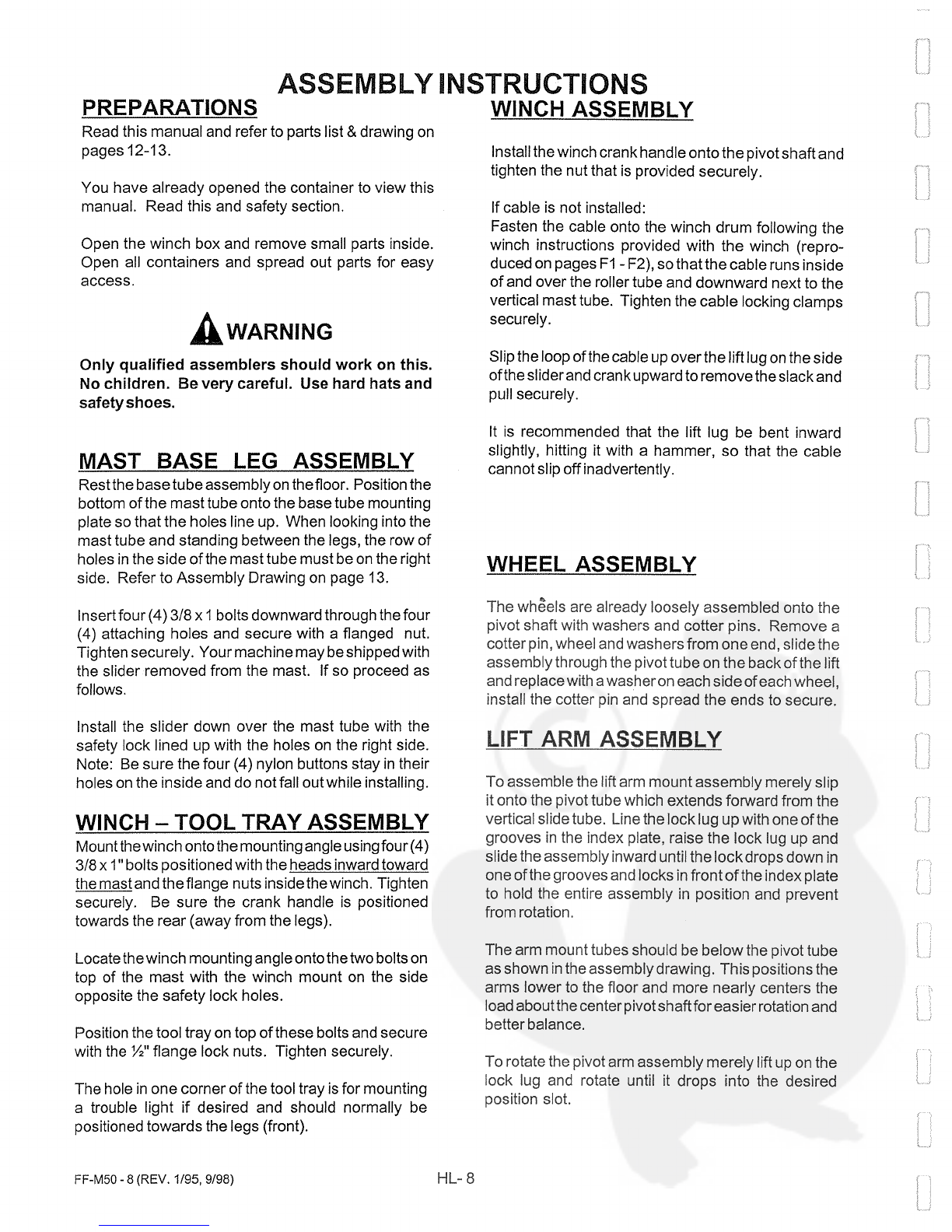
PREPARATIONS
Read
this
manual
and
refer
to
parts
list
&
drawing
on
pages
12-13.
You
have
already
opened
the
container
to
view
this
manual.
Read
this
and
safety
section.
Open
the
winch
box
and
remove
small parts inside.
Open
all
containers
and
spread
out parts
for easy
access.
WARNING
Only
qualified
assembiers
should
work
on
this.
No
children.
Be
very
careful.
Use
hard
hats
and
safetyshoes.
MAST
BASE
LEG
ASSEMBLY
Restthe
base
tubeassembly
on
thefloor.
Position
the
bottom
ofthe mast
tube onto
the
base
tube
mounting
plate
so
that
the
holes
line
up.
When
looking
into
the
mast
tube
and
standing
between
the
legs,
the
row
of
holes
in
the
side
of
the
mast
tube
must
be
on
the right
side.
Refer
to
Assembly
Drawing
on
page
13.
Insert
four
(4)3/8
x
1
boits
downward
through
the
four
(4)
attaching
holes
and
secure
with
a
flanged
nut.
Tighten
securely.
Your machine
may
be
shipped
with
the
slider
removed
from
the
mast.
1f
so
proceed
as
follows
Instali
the
slider
down
over
the
mast
tube with the
safety
lock lined
up
with
the
holes
on
the right
side.
Note:
Be
sure the
four
(4)
nylon
buttons
stay
in
their
holes
onthe
inside
and
do
not
fall
outwhile
installing.
WINCH
-
TOOL TRAY
ASSEMBLY
Mount
the
winch
ontothe
mounting
angle
using
four
(4)
3/8
xl”
boits
pos
itioned with the
heads
inward
toward
the
mast
and
theflange
nuts
inside
the
winch. Tighten
securely.
Be
sure
the
crank
handle
is
positioned
towards
the
rear
(away from
the legs).
Locate
thewinch
mounting angle
onto
thetwo
boits
0fl
top
of
the
mast
with
the
winch
mount
on
the
side
opposite
the
safety
lock holes.
Position
the
tool
tray
on
top
of
these
bolts
and
secure
with
the
Y2”
flange
lock nuts.
Tighten securely.
The
hole
in
one
corner
of
the
tool
tray
is
for mounting
a
trouble
light
if
desired
and
should
normally
be
positioned
towards
the
legs (front).
Instail
the
winch crank handle
ontothe
pivot
shaft
and
tighten the
nut
that
is
provided
securely.
1f
cable
is
not
installed:
Fasten
the cable
onto
the
winch
drum
following
the
winch
instructions
provided
with
the
winch
(repro
duced
on
pages
F1
-F2),
so
thatthe cable
runs
inside
of
and
over
the
roller tube
and
downward
next
to
the
vertical mast
tube.
Tighten
the
cable
locking
clamps
securely.
Slip the loop
of
the
cable
up
over
the
lift
lug
on
the
side
ofthe sliderand
crank
upward
to
remove
the
slack
and
pull
securely.
It
is
recommended that
the
lift lug
be
bent
ifiward
slightly,
hitting
it
with
a
hammer,
so
that
the
cable
cannot
slip
off inadvertently.
WHEEL
ASSEMBLY
The
wh~els
are
already loosely
assembied
onto
the
pivot
shaft
with
washers
and
cotter
pins.
Remove
a
cotter
pin,
wheel
and
washers
from one
end,
slide
the
assembly
through
the
pivot
tube
on
the
back
of
the
lift
afid replace
with
a
washeron
each
side
of
each
wheel,
install the
cotter
pin
afid
spread
the
ends
to
secure.
LIFT ARM
ASSEMBLY
To
assemble
the
lift
arm
moufit assembly
merely
slip
it
onto the
pivot
tube which
extends
forward
from
the
vertical
slide
tube.
Line
the
lock
lug
up
with
one
ofthe
grooves
in
the
index
plate,
raise the
lock
lug
up
and
slide
the
assembly
inward
until
the
lock
drops
down
in
one
ofthe
grooves
and
locks
in
front
of
the
index plate
to
hold
the
entire
assembly
in
position
and
prevent
from
rotation.
The
arm
mounttubes
should
be
below
the
pivot
tube
as
shown
in
the
assembly
drawing. This positions the
arms
lower
to
the
floor
and
more
nearly
centers the
bad
about
the
center
pivot
shaftfor
easier
rotation
and
better
balance.
To
rotate
the
pivot
arm
assembly merely
lift
up on
the
bock
lug and
rotate
until
it
drops
into the
desired
position
slot.
ASSEMBLY
ONSTRUCTIONS
WINCH
ASSEMBLY
FF-M50
-8
(REV. 1/95,
9/98)
HL-8

ASSEMBLY
INSTRUCTIONS
NOTE:
It
is
not
necessary
to
lubricate
the
pivot
assembly,
it
will
rotate
rather
hard with
a
heavy
bad
but
this
is
an
advantage
in
holding
it
in
position
as
one
rotates.
Lubricant
may
be
used
if
desired.
Now slide the
lift
arms
into
the
square sleeves
on
the
arm
mount
assembly.
NOTE:
8e
surethelongerliftarm
is
on
the
leftside
as
facing
the vertical mast
tube
and
the
shorter
one
is
on
the
right.
This
will put
the ends
of
the
arms
approxi
mately
even. Slide
them
into
desired
position
and
secure
with
the
%~‘
balI
lock
pins
in
the
desired
hole.
When preparing
to
lift
a
bad,
it
is
desirable
to
keep
the
lift
arms
approximately equally
spaced
from the
center
pivot
so
that
the
bad
will
be
centered.
~WARNJNG
Tie
any
bad
securely
on
both
sides
before
raising
and
remove
the
spark plug
wire
before
servicing.
DO
NOT
RUN
ENGINE
ON
LIFT.
Be
careful
of fuel,
oil
or
acid
spillage
when
rotating
and
hold
securely.
Do
not
allow
fire
cbose
to
an
eng
me.
Keep
all
safety
Iocks
in
place,
secure
and
operat
ing
properly
Lower
bad
(keeping
feet
away
from
the
lift
area)
before
leaving.
Add
on
wheel
cup.
The
wheel
cup
extension
is
a
loose
piece which
may
be
positioned
any
place along
either
side
to
accommodate
a
wheel
of
a
machine
that
has
an
odd
(not
evenly
spaced)
wheel
positioning.
This
is
particularly
notable
on
the Lawn
Boy,
in
which oase
the
wheel
cup
should
be
positioned
to
the
outer
set
of
holes
on
the right
side
to
accommodate
the
right inner
rearwheel
of
the
push
mower.
Bolt
it
in
place with
two
(2) 3/8
x
1”
bolts
and
flange
nuts.
CHECK
OUT
The
vertical
slidershould
now
slidefreely
up
and
down
the
column
using
the
winch
handle.
It
takes ten
(10)
turns
to
fully
raise or
lower.
NOTE:
It
is
necessary
to hold
the
safety
lock
away
from
the
tube
while
bowering
as
itwill
stop
in
each
hobe
as
t
bowers
past
it.
The lower
area
has
no
holes
to
ease
bowering
once the
bad
is
out
of
the
normal
work
range.
No bubrication
is
required
on
the
vertical slider
column.
The
rollers should
roll
freely
and
there
will
be
no
significant
bad
on
the
slider washers
except when
a
bad
is
offset
considerabby
to
one side.
Machine
should now
be
ready
for
use.
CAUTION
Check
to
make
sure
that
all
parts
are
installed
and
positioned
the
same
as
shown
on
the
parts
drawing.
Do
not
exceed
250#
bad
and
don’t
lift
it
all
on
one
(1)
arm.
CHECK
0FF
Check
the
machine against
the
drawings
and
com
plete
the
pre-use check
list
on
page
4.
Read
the
operating
instructions
and
check
Lit’L
HEFTEEto
be
sure
all
functions operate
properby
and
safeby.
CAUTION
Do
not
albow
anyone
on
or
under
lift
when
operating.
Use
Lit’L
HEFTEEonIy
on
a
level
firm
floor.
FF-M50
-9
(REV.
1/95,
9/98)
HL-9
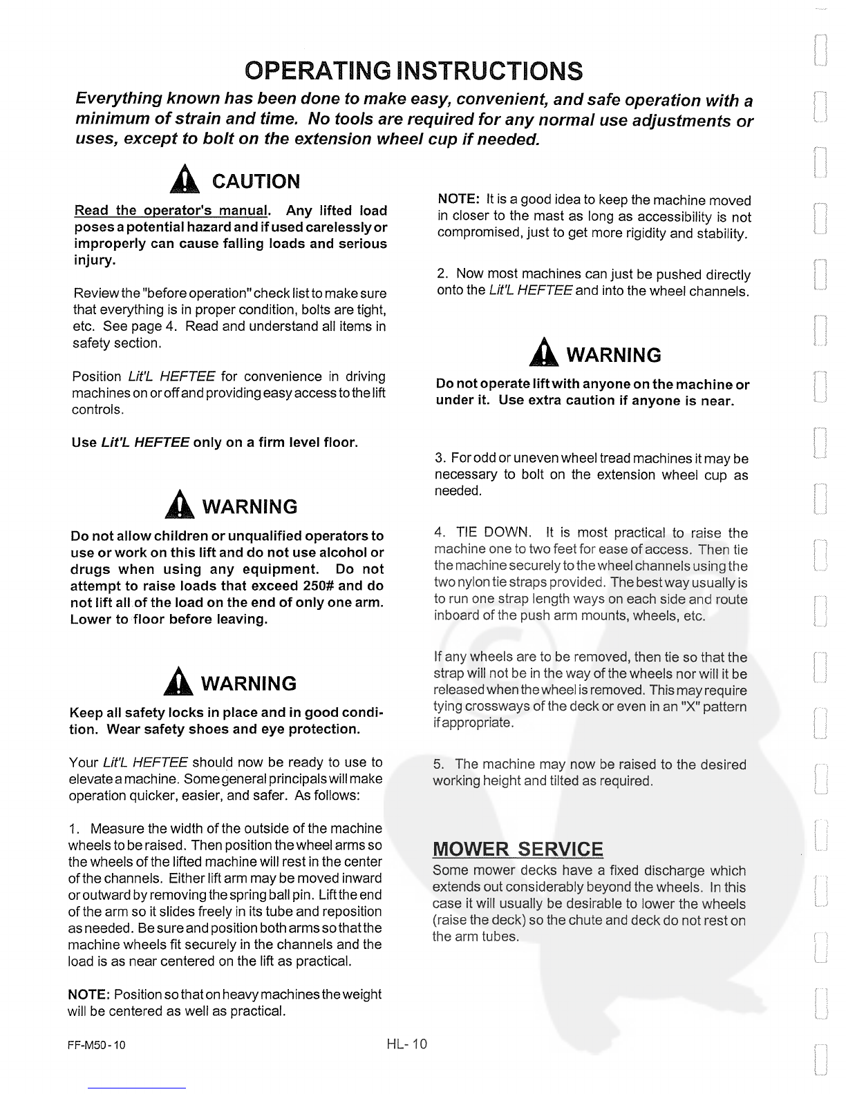
CAUTION
Read
the
operator’s
manual.
Any
lifted
bad
poses
a
potential
hazard and
if
used
carelessiyor
improperly
can
cause
falling
loads
and
serious
1
nj
u
ry.
Review
the
“before operation”
check
list
to
make
sure
that everything
is in
proper
condition,
bolts
are tight,
etc.
See page
4.
Read
and
understand
all
items
in
safety
section.
Position
Lit’L
HEFTEE
for convenience
in
driving
machines
on
oroif
and
providing easy access
to
the
lift
controls.
Use
Lit~L.
HEFTEE
only
on
a
firm
level
floor.
WARMNG
Do
not
albow
children
or unqualified
operators
to
use
or
work
on
this
lift
and
do
not
use
alcohol
or
drugs
when
using
any
equipment.
Do
not
attempt
to
raise
loads
that
exceed
250# and
do
not
lift
allof
the
bad
on
the
end
of
only
one
arm.
Lower
to
fboor
before
leaving.
WARNING
Keep
all
safety
locks
in
place and
in
good
condi
tion.
Wear
safety
shoes
and
eye
protection.
Your
Lit’L
HEFTEE
should now
be
ready
to use
to
elevatea
machine.
Somegeneral principalswill
make
operation
quicker, easier,
and
safer.
As
follows:
1.
Measure
the
width
of
the
outside
of
the
machine
wheels
to
be
raised.
Then
position
thewheel
arms
so
the
wheels
of
the
lifted
machine
will
rest
in
the
center
of
the
channels. Either
lift
arm
may
be
moved
inward
or
outward
by
removing
the
spring
balI
pin.
Liftthe
end
of
the
arm
so
itslides
freely
in
its
tube
and
reposition
as
needed.
8e
sure
and
position
both
arms
so
thatthe
machine
wheels fit securely
in
the
channels
and
the
bad
is
as
near
centered
on
the
lift as
practical.
NOTE: Position
so
that
on
heavy
machines
theweight
will
be
centered
as
well
as
practical.
NOTE:
It
is
a
good
idea
to
keep
the
machine moved
in
closer
to
the
mast
as
long as
accessibility
is
not
compromised,
just
to
get
more
rigidity
and
stabibity.
2.
Now
most machines
can
just
be
pushed
directly
onto the
Lit’L
HEFTEE
and
into
the
wheel
channels.
WARNING
Do
not
operate
lift
with
anyone
on
the
machine
or
under
it.
Use
extra
caution
if
anyone
is
near.
3.
For
odd
or
uneven
wheel
tread
machines
it
may
be
necessary
to
bolt
on
the
extension
wheel
cup
as
needed.
4.
TIE
DOWN.
It
is
most
practicab
to
raise
the
machine
one
to
two
feet
for
ease
of access.
Then
tie
the
machine
securely
to
the
wheel
channels
using
the
two
nylon tie
straps
provided.
The
bestway
usually
is
to
run
one
strap length
ways
on
each
side
and
route
inboard
of
the
push
arm
mounts,
wheels,
etc.
1f
any
wheels
are
to
be
removed,
then
tie
so
that
the
strap
will
not
be
in
the
way
of
the
wheels
nor
will
t
be
released
when
the
wheel
is
removed.
This
may
require
tying
crossways
of
the deck
or
even
in
an
DX”
pattern
ifappropriate.
5.
The
machine may now
be
raised to
the
desired
working
height
and
tilted
as
required.
MOWER
SERVICE
Some
mower
decks
have
a
fixed
discharge which
extends
out
considerably
beyond
the
wheels.
In
this
case
t
will
usually
be
desirable
to
lower
the
wheels
(raise the
deck)
so
the
chute
and
deck
do
not
rest
on
the
arm
tubes.
OPERATIING
INSTRUCTIONS
Everything known
has
been
done
to
make
easy,
convenient,
and
safe
opera
tion with
a
minimum
of
strain
and
time.
No
tools
are
required
for
any
forma!
use
adjustments
or
uses,
except
to
bolt
on
the
extension wheel
cup
ifneeded.
FF-M50-
10
HL-
10

OPERATING INSTRUCTIONS
DANGER
Always
tie
down
the
machine
securely
on
both
sides
before
working
on
it.
Operate and/or
rotate
carefully
and
use
the
standard
tie downs
always.
When
rotating
be
careful
of
spilling
gasoline, oil,
battery
acid,
etc.
Do
not smoke
or
allow
fire
near
machine.
1f
oh
and/or
gas
is
to
be
drained
from
the
machine
by
rotating
or
tipping,
be
very careful
in
placing
the
containerto
avoid
spillage.
Rotating
a
heavy
machine
should
only
be
attempted
with
two
(2)
persons
to
provide
control.
Be
certain
the
tie
straps
are
tight
before
attempting
any
tipping.
WARNING
Remove
the
spark
plug
wire
from
the
engine
beforeattemptinganyservice.
AN
ENGINE
COULD
START
merely
by
pulling
a
blade around
in
the
removal
or
installation
process.
Never
attempt
to run
any
engine
while
on
the
lift.
The
opportunities
for
injury
are
SEVERE
AND
OBVIOUS.
When positioning
the
mowerfor properworking
height,
raise
to
desired
level, then
Iowerenough
sothe
safety
lock
is
engaged
in
the
hole.
Leave the
handle
in
this
position
so
that
the
winch
is
also
supporting
the
bad.
NOTE: When
operating
the
winch
KEEP
CABLE
TIGHT. Any
boose
cable
will
cross
and
twist
on
the
drum.
Then when
tightened,
it
may
have
slack areas
which,
as
the
bad
is
lowered,
will
albow
a
short
dropping
of
the
bad
as
the
slack
is
taken
up.
To
bower,
raise
the
winch
high
enough
so the
safety
lock
may
be
swung
out
of
the
tube, then,
holding the
bock
raised
with
the
left
hand,
lower
the
winch
by
cranking
It
countercbockwise with
the
right hand.
There
are
no
batches
to
reverse
or any other
action
required.
The
handbe
will
stop
wherever
released,
eithergoing
up
ordown.
CAUTION
Nevertry
to
use
the
lift
as
a
hand
truck.
1f
a
mower
must
be
moved
on
the
lift,
lower
it
down
near
the
floor
level
before
tippirig
backwards
on
thewheels.
Also, operate
carefully
so
it
does not
roll
off
sideways.
Keep
feet
away
from
the
base
tube
and
out from
under
the
lift
arms
while
lowering.
Wear
safety
shoes
and
other
protective
clothing
as
appropriate.
OTHER
USES
The Lit’L
HEFTEE
makes
a
very
convenient
lifting
platform
for
raising
a
bad
to
work
on
it.
CAUTION
Do
not
raise
or
lower
the
lift
arms
with
anyone
on
or
under
it. Use
it
for
a
work
table
only
when
the
lift
has
been
lowered
into the
safety
locks.
Always
use
a
pallet
or
other platform that
is
locked
to
the arms
and
under
them
so
that
it
cannot
tip
or
slip
off
of
the
forks.
Asimplework
platformwith
stirrupsthat
go
around
the
arms
can
make
a
real
contribution
to
safety
and
productivity
by
raising
such
things
as
engines, tooling,
or
other
hard
to
handbe
difficult
objects
to
a
level
most
convenientforworking
on
etc.
OTHER
ATTACHMENTS
The
entire
lift
arm
and
mountassembly
may
be
slid
off
of
the
vertical
slider
mereby
by
raising
the
pivot lock
in
one
of
the
grooves
and
sbiding
the
assembly
offthe
end
of
the
tube.
To
use
the
engine
mount,
chain saw,
or
string
trimmer
brackets,
just
remove
the two
(2)
lift
arms
and
insert
the
desired
service
bracket.
The
most
convenient
positions
are
shown
in
the
brackets
draw
ing.
As
can
be
seen
by the
great
extent
to
which
safety
has
been
considered
on
this
machine,
we sincerely
hope
that
no
one will
ever
be
injured
or
hurt.
We
cannot
guarantee
that,
as
anything
can
cause
harm
if
used
improperly, even
a
rock.
Any
raised
heavy object
is
a
potential
hazard
if
it
shoubd
fabb
with
someone
under
neath.
PLEASE
USE
WITH
CAUTION
AND
RESTRAINT.
CAU11ON
Before
leaving
Lft’L
HEFTEE
always
lower
it
to
the
ground to
discourage
uriauthorized
use
by
the careless, the
unqualified,
or
children.
FF-M50
11
(REV.
1/95,
4/95)
HL-
11

PARTS
LIST
FOR
Lît’L
HEFTEE
MAIN
ASSEMBLY
2....
3....
4....
5....
6....
7....
8....
9....
10
11
.
12
DR
USE
12*.
13A
14
15
16
16A...
18
19
20
21
22
23
24
1
1
1
1
1
1
1
1
1
1
1
2
2
1
1
1
2
O/L*
-
OBTAIN
LOCALLY
A/R**
-
AS
REQUIRED
HARDWARE
O/L*
8
3/8’
FLAT
WASHER
(used
on
early
machines)
10
3/8’
NC
FLANGE
HEX
LOCK
NUT
2
3/32
X 1-1/4”
COTTER
PIN
10
3/8NCXI”HEXHEADCAPSCREW
2
1/16
X
3/4”
COTTER
PIN
2
3/8X4-1/2”HEXHEADCAPSCREWG5
2
1/2”FLANGEHEXLOCKNUT
2
1/2”SAE
FLAT
WASHERS
6
3/8”FLANGENONLOCKNUT
2
3/8”
TOP LOCK NUT
FF-M50-
12
(Rev.
5/95, 6/95,
9/95.11/96,12/97,1/98,4/98,
HL-
12
9/98,
3/99,
9/99)
1
REF.
NO.
PART
#
NO.
REQ.
DESCRIPTION
1
....
HL129
HF265
4
HL147
1
HL146
1
HL165
1
HLI5O
1
HLII3
2
HL139
1
HL132
1
HL155
1
MF658
1
HLI2I
4
12*
BELOW
FOR
MODELS
AFTER
SH2693
2
+
2-HLI2I
13....
HL218
1
HL123
1
HLI2O
1
HL1I9
1
‘HL163
HL162
HL116
HL137
HL143
HL126
MF659
HL138
HL153
BASE
LEG
TUBE
ASSEMBLY
PLASTIC
END
PLUG
LONG
LEFT
LIFT
ARM
ASSEMBLY
SHORT RIGHT
LIFT
ARM
ASSEMBLY
EXTENSION
ADD-ON WHEEL
CUP
ARM
MOUNT
ASSEMBLY
14”
X
2”
BALL
SPRING
PIN
WITH
RING
SWIVEL
LOCK
LATCH
SLIDER
TUBE
ASY w/
ROLLERS
&
BUSH1NGS,
ETC.
COMPLETE
SWIVEL
LOCK
COMPRESSION
SPRING
14
X
3,4
DRILLED PIVOT
PIN
1-1/8”
OD
X
1/16
THICK
NYLN FLANGE BEARING
(SLIDER
BUTTON)
5-1-95
—
these
are
included
in
HL123
3/4”
OD
NYLON
BEARING
W/
1/8
THICK
FLANGE
(used
after
5/1/95)
1-1/8”
OD
X
2-7/8”
LONG
STEEL
ROLLER
W/BEARINGS
(changed
5/98)
SET
OF
2
ROLLERS
WITH
BEARINGS
&
NYLON
SIDE
SPACERS
WINCH
CABLE
1/8
X
62”
LONG
1
TON
SAFETY
LOCK
WINCH
WITH
HANDLE
AND
CABLE ROLLER
(NO
CABLE)
5/8
OD
X
3-5/8”
STEEL
PIPE
CABLE
ROLLER
Always order
7/16
x
3-3/4” FRAME
SPACER
SLEEVE
in
pairs
WINCH
HANDLE
TOOL
TRAY
WINCH
MOUNT
ANGLE
VERTICAL MAST TUBE
ASSEMBLY
5/16
X
1-1/4”
DRILLED
LOCK
PIN
SAFETY
LOCK
DOG
SAFETY LOCK
TORSION
SPRING
SAFETY DECAL
SAFETY DECAL
LIT’L
HEFTEE
DECAL
4”
DIA.
WHEEL
WHEELAXLE
ROD
-WELD
ON
NOW-WAS
SEPARATE
ON
PRIOR
MODELS
PATENT DECAL
DECALSET
NYLON
TIE
DOWN
STRAPS
25
....
HLIO7
26
....
HL1O8
27
....
HLII4
28
....
HL154
29
....
HL159
30
....
STI5I
31
.
...
HL168
32
....
HF235
40
(early
models)
41
Oi’L~
42
O/L*
43
O/L*
44
O/L*
45
O/L*
46
O/L*
47
O/L*
48
O/L*
49
O/L*

L1rL HEFTEE
MAIN
ASSEMBLY
FF-M50
-13
(REV.
7/94,
1/95,
5/95,
6/95,
9/95,
1/98,
4/98,
9/98,
9/99)
\49
NOT
SHOWN
~—DECAL
SET
~—TIE
DOWN
STRAPS
HL-13
SERVOCE
ONSTRUCTIONS
CAU11ON
Read
the
operator’s
manual before
trying
to
operate or
service.
Any
lifted
bad
poses
a
potential
hazardarid
if
used
carelessly
or
im
properly
can
cause
falling
loads
and
serlous
i
njury.
WARNING
Do
not
allow children or unqualified
operators
to
use
or
work
on
this
lift
and do
not
use
alcohol
or
drugs
when
using
any
equipment.
Do
not
attempt
to
raise
loads greater
than
it
will
easily
lift.
Do
not
exceed
250#.
Lower
to
floor
before
leaving.
The
Lit’L
HEFTEE
has
been
designed
to
minimize
service
as
much
as
possible.
Refer
to
parts
drawings
and
safety
pages
before
working
on
Lift
HEFTEE.
INSPECTION
Periodically
check
your
Lit’L
HEFTEE
carefully
for
loose bolts,
proper
cable
lay
and
any
sign
of
cracks,
kinks
or
frayed
areas.
Replace
if
found.
DO
NOT
USE
if
any
problems
are
found. Your
safety
depends
on
it.
LUBRICATJON
1.
The rollers
used
after
4-98
in
the
slider
are solid
steel with
bronze
busings.
These
need
to
be
removed
orjust
remove
the bolt and
squirt
grease
into
the
base.
2.
The
rollers,
referto
#1
6,
page
13,
on
which
the
cable
rods
must
be
removed
and
insert
grease
to
prevent
wear
and
drag.
3.
The
arm holder,
refer
to
#6,
page
13,
will
rotate
easily
if
grease
is
added
to
the bore.
MAINTENANCE AND
REPAIRS
Proceed
as
follows.
SLIDER
ROLLER
BEARINGS.
1f
any
portion
of
the
slidertube
comes
within
1/32
of
an
inch,
underload,
oftheverticalmasttube,
itmeansthe
rollers
or
slider washers
are
worn
or
damaged
and
should
be
replaced.
Repair
as
follows.
First,
remove
the
arm
assembly
from
the
slider
tube
pivot
shaft
by
lifting
the rotation
lock
in
one
of
the
grooves
and
just
pulling
the
assembly
off
the
pivot
shaft.
It
is
easier
to
hand
le
if
the
lift
arms
are
removed
from this
assembly
first,
but
may
be
done
eitherway.
To
replace,
unhook
the
cable
from
the
slider
tube, this
may
require bending
thetab out
slightly
as
it
may have
been
bent
in
after installation.
Remove the
tool
tray
and
winchfrom
the
top
ofthe
mast
by
removing
the
two
(2)
Y2”
nuts.
Now
slide
the
slider
tube
assembly
off
the
top
of
the
mast,
being
careful
not
to
loose the nylon
wear
buttons
or
allow them
to
drop
inside
the
tube.
Check
the
rollers
and
pivot
boltfor
clearance.
1f
loose,
floppy,
worn,
etc.,
replace these
rollers.
Merely
remove
the nut
and
slide the
bolt
out,
insert new
part.
Grease
the
roller
and
slide
the
bolt
back
in
and
tighten
the nut
securely.
Do
not
try
to
tighten
it
up
solid
against
the
rollers.
See
p.
13
for
proper
assembly,
To
replace,
the
butttons
hold
them
in
place
so
they
do
not
fall out.
You
may
use
silicone
glue
or
grease
to
help hold
in
place.
Next,
lower
the
slider
assembly
back
onto
the
vertical masttube
and
replace
the
winch
and
tool tray,
re-attach
cable,
and
lower
the
slider
tube
till
the
cable
is
tight.
CAUTION
Alwayswear
safety
shoes
and
safety
glasses
and
proper
clothing
when
doing
service
work
on
the
LîtL
HEFTEE
or
anything
else.
Lower
into
safety
locks
before
working
on
L1t7..
HEFTEE.
WARNING
Do
not
operate
lift
with
anyone
on
the
machine
or
under
it.
Use
extra
caution
if
anyone
is
near.
CAUTION
Keep
all
safety
locks
in
place
and
in
good
condi
tion.
SAFETY
LOCKS
Check
both
safety
lock
pivot
pins,
springs
and
mounts
to
be
sure
they
are
in
good
condition
and
snap
securely
into
locked
position. Repair
or
replace
as
needed.
Replace
any
decals
immediately
if
damaged.
Clean
area
for
decal
with
soap
and
water.
Re
move any
dirt,
grease
or remnants
of
old
decal.
Reapply
pressure
serisitive
decal
in
same
loca
tion.
WINCH REPAIR
See Fulton page
1-2
for
instructions
and
parts.
Order
parts
from
McCanse Engineering
using Fulton
Part
Numbers
shown.
FF-M50
-
14
(5/98)
HL-
14
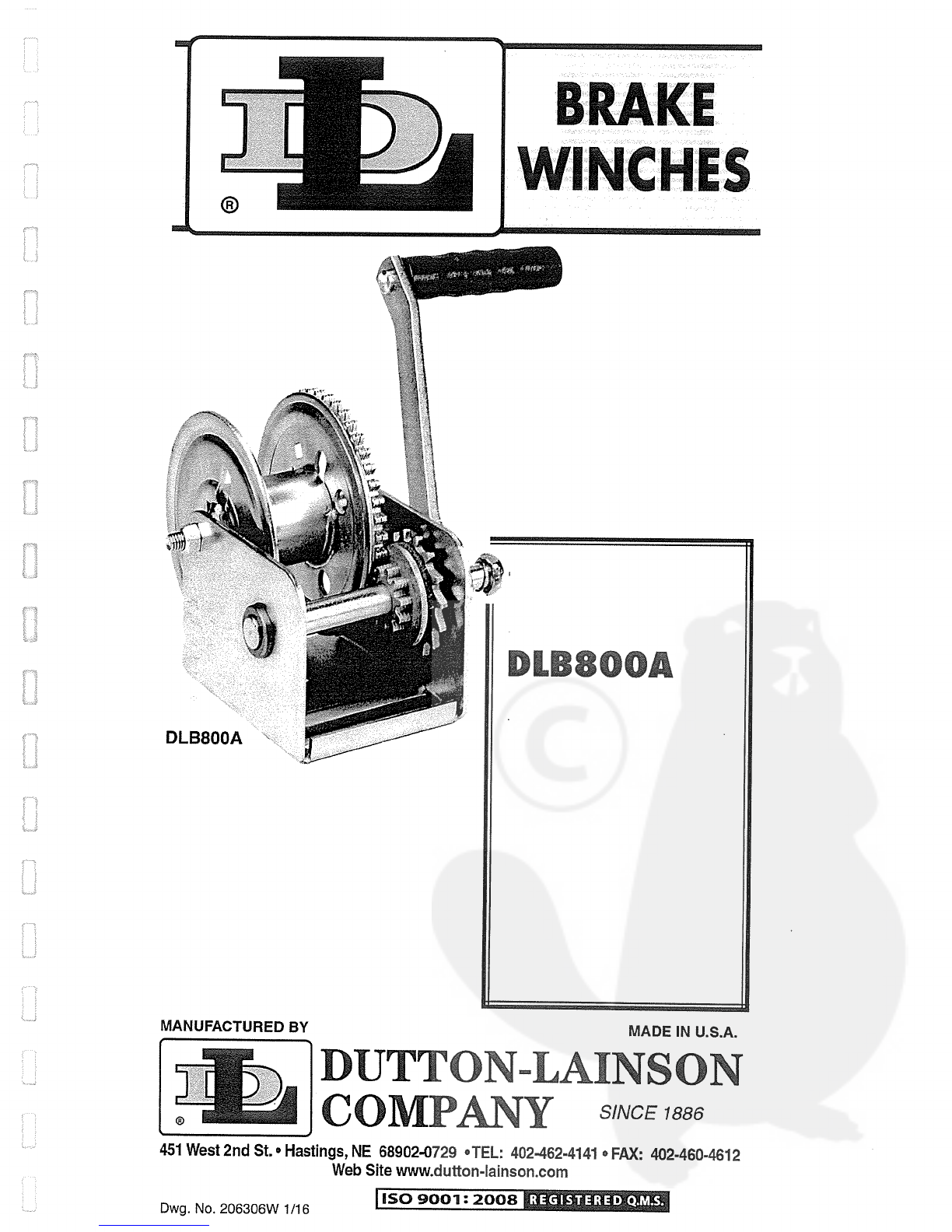
BRAKE
WINCHES
~
DLBBOOA
_______________
MADE
IN
U.S.A.
DUTTON~LAINSON
____
COMPANY
SINCE
1886
451
West
2nd
St.
Hastings,
NE
68902-0729
OTEL:
402-462-4141
e
FAX:
402-460-4612
Web
Site
www.dutton-Iainson.com
i~j
DLB800A
MANUFACTURED
BY
Dwg.
No.
206306W
1/16
1
ISO
9001:
2008

Original
lnstructions
ENGLISH
IMPORTANT SAFETY INFORMATION
o
This
brake
winch
is
built
for
multi-purpose
hauling
and
lifting operations. It
is
not
to
be
used
as
a
hoist
for
lifting,
supporting
or
transporting
people,
or
for
loads
over
areas
where people
could
be
present.
•
Respect
this
winch.
High
forces
are
created when using
a
winch, creating potential
safety
hazards.
It
should
be
operated
and
maintained
in
accordance
with
instructions.
Never
allow
children
or
any
one
who
is
not
familiar
wiih
the operation
of
the
winch
to
use
it.
A
winch
accident
could
result
in
personal injury.
•
Check
winch
for
proper
operation
on
each use.
Do
not
use
if
damaged.
Seek
immediate
repairs.
• Never
exceed rated
capacity.
Excess
bad
may
cause
premature
fallure
and
could result
in
serious
personal injury.
This
winch
is
rated
on
first
layer of
cable
on
the
hub.
Using
more
layers
of cable
increases
the
bad
on
the
winch.
•
Never
apply
bad
on
winch
with
cable
fully
extended.
Keep
at
least
three
full turns
of
cable
on
the
reel. Check
cable
on
every
use. Replace
at
the
first
sign
of
kinks,
broken wires,
deformation or
any
other
damage.
•
Secure
bad
properly.
When
winching
operation
is
complete,
do
not
depend
on
winch
to
support
bad.
•
Operate
with
hand
power
only.
This
winch
should
not
be
operated
with
a
motor
of
any
kind.
1f
the
winch
cannot
be
cranked easily
with
one
hand,
it
is
probably over-loaded.
•
1f
winch
will
be
used
in
freezing,
icy
conditions,
apply
silicone spray
to
ratchet
pawl
and
spacer
items,
V,
W,
X,
or
Y.
Do
n~f
spray
other
brake
mechanism
parts.
WINCH
MOUNTING AND
CABLE
ATTACHMENT
—
For
maximum
strength
and
safe
ty,
this
winch should
be
mounted with
three
3/8
bolts
(Ml0),
washers
and
lock
washers,
Usa
Grade
8
for
1500
lb/680
kg
or
greater
capacity.
(Sea
parts
drawing).
Using
fewer
bolts
or
alternate
locations
will
result
in
damage
to
the
winch
base
and
the
winch
may
malfunction.
Attach
cable
or
rope
by
method shown
in
sketch.
OPERATING
INSTRUCTIONS
—
Wind
cable
on
winch
real
by
turning
winch
handle
in
clockwise
direc
tion.
This should
produce
a
loud,
sharp,
clicking
noise.
The
bad
will
remain
in
position
when the
han
dle
is released.
Wind
cable
off
the
winch
reel
by
turn
ing
winch
handle
counterclockwise
(no noise
will
be
produced).
The
bad
will
remain
in
position
when
the
handle
is
released,
but
for
extra
security
it
is
recom
mended
that the
handle
be
turned clockwise
until
at
east
two
clicks
are
heard.
This
will
add
extra
tightness
to the
brake
mechanism.
Always satisfy
yourself that
the
winch
is
holding the
bad
before
releasing the
winch
handle.
4~kIMP0RTANT:
Sufficient
laad
must
ho
applied
to
the
cahbe
to
overcome
internal
resistance
and
oper
ate the
brake
properly,
otherwise turning
the
crank
handle
countercbockwise
will
only
remove the
han
WINCH
MAINTENANCE
—
In
order
to
insure
maximum performance,
a
periodic
inspection
for
any necessary
preventive
maintenance
should
be
made.
Check
at east
once
annually
and
more
fre
quentby
when
the
winch
is
exposed to
an
environ
ment which
is
particularly
dirty
or
wet,
For
continued
smooth performance
and
increased
life,
occasional
ly
grease
gears,
real
shaft and
handle
threads.
An
dle
from
the
shaft
—
the
real
will
not
turn.
The
mini
mum
operating
bad
requirement
is
50
1h
(23
kg)
for
Models
DLB35OA,
DLB35OAG,
DLB800A,
DLB800AG,
DLB1200A
and
DL.B1200AG,
75
1h
(34
kg)
for
DLB1500A and
Db..B1500AG,
175
1h
(80
kg)
for
Dl..B2000AG
and OLB2500A.
Models
DLB8O5A,
DLB12O5A,
DLB15O5A
&
DLB25O5A
are
equipped
with
a
lockout
lever
for
the
purpose
of ‘freewheeling’
cable
out
when
there
is
no
bad
on
the
winch.
To
‘freewheel’
cabbe
out,
simply
turn
the
handle
countercbockwise
until
bockout lever
can
be
engaged
behind
handle
hub.
In
this
condition
cable
can
be
easily
pulled
from
the
winch drum.
A~h..
WARNING:
Never
put
winch
in
freewheel
mode
if
any
potential
for
a
bad
on
the
cabbe
exists. Engaging
the
bockout
lever
keeps
the
winch
from
stopping
in
the
event
that
a
bad
is
accidentally
applied.
occasionab
drop
of
oib
on
the
drive
shaft bearings
is
also
recommended.
1f
winch
will
be
used
in
freezing,
icy
conditions,
apply
silicone spray to
ratchet
pawl
and
spacer
items
V,
W, X
or
Y~
Note:
Do
not
oib
or
grease
brake
mechanism items
H
and
J.
Keep
winch
in
good
working
order.
Damaged
or
severely-worn
parts
create
unnecessary dangers
and
could
resubt
in
personal
injury
or
property
damage.
4~
WARN
ING
READ
INSTRUCTIONS
CAREFULLY BEFORE
ATrEMPTING
To
INSTALL,
OPERATE
OR
SERVICE
THIS WINCH.
FAILURE
TO
COMPLY
WITH
INSTRUCTIONS COULD RESULT
IN
SERJOUS
OR
FATAL INJURY. RETAIN
THESE
INSTRUCTIONS
FOR
FUTURE REFERENCE.
ASSEMBLY
—
Thread
the
handbe
onto
the
winch
drive
shaif
and
be
certain
that
a
clicking
noise
is
pro
duced when
the
handle
is
turned
cbockwise.
Install
the
spring
and bocknut
(Items
E
and
G)
on
the
end
of
the
drive
shaft
as
shown
on
parts
drawing.
These
parts
may
appear
to
serve
no
function,
but
they
pro
vide
several
important
faib-safe
features,
and
should
not
be
altered
or
removed.
NOT
FOR
THE
MOVEMENT
OF
HUMAN BEINGS

Hef
Descrlptlon
Part
No.
A
Base
404900*
A
Base
—
DLB
SSOAG
404945*
8
Bushing
204012
C
‘E”
Ring
205116
D
Drive
Shaft
306061
E
Spring
204364
F
Handle
—
7”
5703061
Handle
—9-3/8” 5703103
G
Nut
205033
H
Pressure
Plato
204362
H
Pressure
Plate
“3”
SerIes
206620
To
order
replacement
parts
contact:
Dutton-Lainson
Company
Www.dlco.com
Tel:
800-569-6577
Fax:
402-460-4612
e-mail:
DLsales@dutton-lajnson.com
DLB800A
&
DLB800AG
Winch
AE
w
AK
D
H
‘J.
L
PARTS
liST
Rot
Descrlptlon
Part
No.
AH
Lockout
Lever
(optional)
404579
AJ
Spacer
(optlonal)
406160
AK Gear
Cover
(optional)
Painted Bronze
5240346
Plated
5240361
AL
Base
404896*
Base
—
DLB
1
200AG
404897*
AM
Bushing
204009
AN
Gear
Cover—
“G”
Series
406115
J
Ratchet
Wheel
404164
ALl
(3ear
Cover
(optlonal)
Painted Bronze
Plated
5240122
5240221
1<
PressureWasher
404163
AR
SpacerWasher
205120
L
Bushing
206328
AS
Real
304754*
M
Nut
205316
AS
Real —
1-7/8” (optlonal)
304768*
N
Bolt
205332
AT
Base
404891*
P
Rope
Clamp
Kit
5243506
—
Base
—
DLB
1500AG
404892*
Q
Gear Cover
—
“G”
Series 406114
AU
Drive
Shaft
304760
S
Reel
306075*
AV
Hancile
—
9-3/8” 5703103
Real
-
DLB35OAG
306167
—
Handle
—
12”
5703111
T
Locknut
204803
AW
Bolt
204804
U
Bolt
205167
AX
Reel
Spacer 204808
V
Flat
Washer
205055
AY
Gear Cover
(optional)
W
PawI
404409
Painted Bronze
5240387
PawI
—
‘G”
Series
404190
—
Plated
5240403
X
Spacer 404166
AZ
Reel
304755*
Spacer —
‘G”
Series
404191
BA
Base
—
DLB2500A
406047*
Y
Spring
204363
Base
—
DLB
2000AG
404899*
Spring
—
‘G”
Series
204460
BB
Spacer
404434
Z
RoeI
Spacer
207183
BC
Bolt
205006
AB
Bolt 203161
BD
Flat
Washer
205139
AC
Real
Spacer
204807
85
Intermed.
Drive
Shaft
306035
AE
Reel
306062*
BF Nut
205014
AF
Base
Base
—
DLB
aOoAG
404893*
404895*
BH
Real
304756*
BJ
Drive
Hub
(Optional)
304562
BM
Handle
w/Lock
Fin
(Opt)
5703426
BN
Handle
Hub
(Optional)
304630
BP
Special
Nut
(Optional)
404970
BQ
“5”
Ring
206162
8H
Bushing
206163
88
Bolt
205335

Table of contents
Popular Lifting System manuals by other brands


Magliner
Magliner LiftPlus Lite owner's manual

Schmalz
Schmalz JumboPicker-Flex Operating and maintenance instructions

EZ-ACCESS
EZ-ACCESS Pathway MSTAIR2839 Assembly manual

jost
jost Modul B 01 01 Installation and operating instructions

Ravaglioli
Ravaglioli RAV241-RAV242 manual

ShoreDocker
ShoreDocker SD1200 Assembly and operating instructions
Beacon
Beacon BSSK-1 owner's manual

MoJack
MoJack MoJackPRO Instructions for assembly and operation

Southworth
Southworth ZLS Series owner's manual

Enhance Mobility
Enhance Mobility Hercules instructions

Granberg
Granberg Centerlift 960 installation instructions

Braun Corporation
Braun Corporation UVL Series Service manual