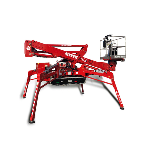
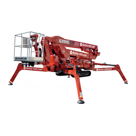
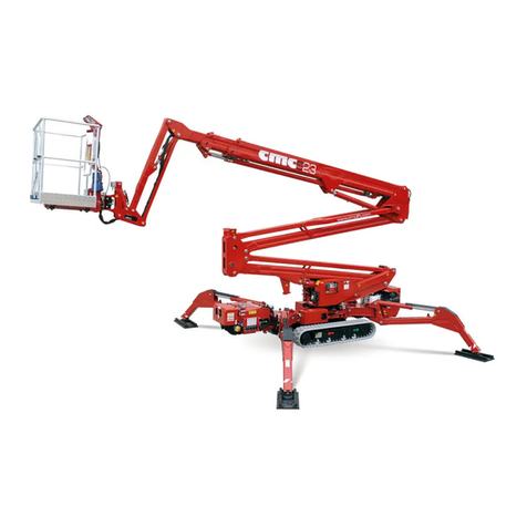
CMC SUP15 User manual

MAN. 161 rev. 5 Use and maintenance manual Sup15
1ª
page of
77
0 Introduction
hank you for choosing to purchase a MEWP (aerial work platform)
CMC, we are sure you will be pleased with your choice.
0.1
Use and maintenance manual
This manual is added to the sold machine and contains the instructions for
its transfer, use and maintenance. While drawing up this manual, we took
into consideration all the operations that are part of a normal use and regu-
lar maintenance of the machine. So for a correct and optimum use, you
have to follow the described instructions carefully.
This manual has been drawn up in order to
:
Describe the use of the machine
Show the main technical specifications of the machine
Provide with the instructions for the placement and use of
the machine
Describe the safety devices
Point out the potential risks and/or possible dangerous sit-
uations
Provide with the necessary instructions for the ordinary
maintenance operations
Provide with the instructions for the filling of the check reg-
ister.
THE USE AND MAINTENANCE MANUAL IS INTEGRAL
PART OF THE MACHINE. In case of sale of the MEWP,
please give this manual to the new owner.
KEY FOR THE SYMBOLS USED IN THIS MANUAL
( CAUTION)
= warns the user about the risk of serious damages to people or to
part of the equipment or the vehicle, if you do not obey the safety
regulations.
(WARNING)
= notifies the possibility of minor injuries to people or little damag-
es to the platform or vehicle PARTS..
( FORBIDDEN) = prohibition signal
(
OBLIGATION ) = obligation signal
(CAUTION)
=warns the user about the risk of environmental
pollution.
*
(OPTIONAL)
=indicates an optional outfit.
( IMPORTANT NOTE)
This instruction manual is addressed to:
Operators
Ground assistants
Staff in charge of the platform (MEWP) guard
Security manager
Maintenance manager
T

MAN. 161 rev. 5 Use and maintenance manual Sup15
2ª
page of
77
0.2
Disclaimer
CMC declines all responsibility in case of partial or total non-
observance of the following instructions
1.
Before proceeding with any operation of installation and
use of the machine, the user is obliged to read carefully the
text of this manual, with particular reference to all the laws
and indications concerning the safety of its use; and he is
obliged to observe carefully these laws and indications dur-
ing all the operations carried out with the MEWP.
2.
This manual cannot replace in any way a suitable experi-
ence that the persons in charge must have gained previously
on similar machines or that they will able to get on this ma-
chine, under the guidance of an already trained staff.
3.
The operator shall carefully observe the safety standards
foreseen by national legislations.
4.
The use of the machine must be entrusted only to trained
and authorized staff.
The non-observance of the aforesaid items automati-
cally invalidates the guarantee.
0.3
Where and how to store the manual
This manual (or its copy) must always be kept on the machine
(in a box mounted on the turret) for any immediate consultation
by the operator and must be kept in good conditions, sheltered
from sunbeams.
0.4
Normative references
This manual has been drawn up according to the following
laws and directives:
EC directive 2006/42/CE UNI-EN 12100 1
a
and 2
a
EN 280:2009
EC directive 91/368 UNI-EN 294 EN 60204-1
EC directive 93/44 UNI-EN 349 CEI-EN 60947-5-1
EC directive 93/68 UNI-EN 418 CEI-EN 60529

MAN. 161 rev. 5 Use and maintenance manual Sup15
3ª
page of
77
0.5
Amendments and integrations
The information and references present in this manual are those in force at
the moment of printing.
Due to the constant and continuous improvement of their product by the
manufacturers, the supplied machine could present some technical specifi-
cations different from those described on this manual. Any change will be
however accompanied with particular attached explaining functional char-
acteristics. In case of difference in comparison with the basic contents of
this manual, the user is kindly asked to contact CMC and ask for supple-
mentary technical specifications
As this manual includes both current and optional components, you could
find information not applicable to your equipment.
CMC reserves the right to update its production and its relation instruction
manuals (without prior notice) according to the development of the tech-
nique, to the acquisition of new experiences and/or to the change of law
provisions, without being anyway obliged to intervene on the previously sold
machines and on their manuals.
No part of this publication can be translated, modified or reproduced (even
partially) without the express authorization of CMC s.r.l.
CMC reserves the right to modify - totally or partially - any datum or specifi-
cation of this publication (without prior notice).
Data and references indicated in it are those in force at the moment of
printing.
Year 2013
CMC s.r.l.

MAN. 161 rev. 5 Use and maintenance manual Sup15
4ª
page of
77
1 Specifications
1.1
Technical sheet and performances
Platform brand
CMC s.r.l.
Platform model
SUP15
Max basket load capacity
200 Kg
(incl: n° 2 people +equipment)
Max height from the ground
of the basket
12,9 m
Max horizontal outreach with
200Kg
6,0 m (at the edge of the basket)
Turret rotation
+/- 180°
Basket size
Basket rotation
0° (the basket is fixed)
Max lifting and descending speed of the MEWP 0,4 m/s
max arm extension and withdrawal speed 0,4 m/s
Max rotation speed 0,7 m/s
MAX TRANSLATION SPEED 0,3 m/s
Max manual force allowed in the basket with 1 operator
400N
Tightening torque
Bolts of the bearing M16 cl 10.9 28 daNm
Max load under the stabilizers 1200 daN
Max specific pressure under the stabilizers 5 daN/cm2
Transversal moving on slope 10°
Max slope allowed surmountable in translation 25% (13°)
Max inclination allowed by the frame 1° (+/- 0.5°)
Crawler length
Crawler width
1207 mm
770 mm
Fuel endothermic engine 8,2 KW / 3600 R M
(REFER TO THE USER MANUAL
DELIVERED)
Batteries
type
voltage / capacity
Lead-acid
12/44 V / Ah
Battery charger supply output
220 V 60 Hz
Electric system voltage 12 V
Electric engine power 2.2 kW
Min and max pressure 70 / 210 bar

MAN. 161 rev. 5 Use and maintenance manual Sup15
5ª
page of
77
1.2
Identification plate
On the turret there is a plate with all the identification data of the machine:
TYPE Sup MANUFACT. CMC
MODEL S15 YEAR 2013
SERIAL NO.
S13A1037 TOT. WEIGHT 1950 K
CAPACITY 200 K INCLUDING 2 PERS.
MAX MANUAL FORCE ALLOWED 40 daN
MAX WIND SPEED ALLOWED 12,5 m/s
MAX FRAME INCLINATION ALLOWED 1 °
EXTERNAL FEEDING 220V 50Hz
C.M.C. s.r.l.
CARATTERISTICHE
S.P. 231 Km1+900
70026 Modugno (BA) - ITALY
Tel./Fax 080.53.26.606/557
http://www.cmclift.com
E-mail: info@cmclift.com
Picture 1: identification plate - facsimile

MAN. 161 rev. 5 Use and maintenance manual Sup15
6ª
page of
77
1.3
MEWP in rest position
Picture 2: Overall drawing with basket connected

MAN. 161 rev. 5 Use and maintenance manual Sup15
7ª
page of
77
1.4 Working diagram and stabilization area
Picture 3: working diagram

MAN. 161 rev. 5 Use and maintenance manual Sup15
8ª
page of
77
Picture 4 - stabilization area (mm)

MAN. 161 rev. 5 Use and maintenance manual Sup15
9ª
page of
77
1.5
Classification
The aerial work platform Sup15 belongs to the group B: during the working
phases, the vertical projection of the load gravity centre can be out of the
turnover lines (EN 280:2009 par. 1.4).
As to the movement, it belongs to the type No 1: the movement is allowed
only when the work platform is in transport position (EN 280:2009 par. 1.4).
1.6
Loading cycles
The machine is expected to live for 40.000 working cycles
1
(i.e. 10 years,
40 weeks per year, 20 hours per week, 5 cycles per hour).
Within this term, the machine must undergo at least 2 (two) in-depth
checks (structural, mechanical, electric, elements, etc.), in case of par-
ticular heavy uses (frequent use at the performance limit, particular unfa-
vourable environmental conditions such as steel systems, paper mills and
so on) it is better to increase the checks. Anyway it is advisable to
have the state of the machine checked by the manufacturer factory or
by an authorized assistance point, at least every 1500 – 2000 working
hours or once a year.
1
Loading cycle: cycle starting from the access position, performing the work and
returning to the access position.
1.7
CE Certification
CMC s.r.l. states under its own responsibility that the MEWP Sup15 was de-
signed and produced in compliance with national and European standards,
and that the machine is identical to the model submitted to control and test
for the “CE” certification by the Notified Institute n° 1878 VERICERT srl Via
Cavina 19 – 48100 Ravenna - Italy

MAN. 161 rev. 5 Use and maintenance manual Sup15
10ª
page of
77
2 Description and purpose
2.1
Definition
The machine is called Sup15 and it is a mobile elevating work platform
(MEWP):
mobile machine designed to take people to the work positions, where they
carry out duties from the work platform, with the understanding that people
get on or off the work platform through a defined access position and that it
is made of at least one work platform with controls, an extendible structure
and a frame. It is forbidden to access or to get off the work platform at
different levels.
2.2
Machine purpose
The aerial work platform Sup15 is an equipment which enables the opera-
tors to reach the working place when this is high-positioned.
The machine has been designed for an essentially vertical development. It
must be carried with the machinery set on the stop position.
The only professional use of the machine is allowed only to
specialized or trained staff.

MAN. 161 rev. 5 Use and maintenance manual Sup15
11ª
page of
77
2.3
Description of the main components
5
8
6
Picture 5: MEWP main components

MAN. 161 rev. 5 Use and maintenance manual Sup15
12ª
page of
77
2.3.1
Frame
1
(
Picture 5
)
Quality steel structure able to equally divide the equipment’s weight when
the MEWP is in transport position. The frame has 4 oil-pressure jack arms
for stabilization [2 front stabilizer cylinders 2 (Picture 5), 2 rear stabilizer
cylinders 3 (Picture 5)]. The basis for the bearing is placed on the frame 4
(Picture 5), it enables the swinging of the equipment through the rotation
group.
2.3.2
Turret
5 (Picture 5)
The turret, in quality steel, is fixed on the bearing. It is started by a hydraulic
engine (whose brake is normally closed), placed inside the turret. It enables
the rotation of the superstructure.
2.3.3
Double Pantograph
6 (Picture 5)
The pantograph is composed by two couples of parallel arms (Picture 5)
and by the pantograph connecting rod 7. The arms (tubular with rectangu-
lar section, press-formed and electro welded) and the connecting rod are in
quality steel sheets. The movement of the pantograph (pantograph lifting
and descent) is realized by the pantograph lifting oil-pressure cylinder. This
cylinder is hinged to the turret (rod side) and to the pantograph upper crank
(stem side) and it has a double effect balancing valve This cylinder is
hinged to the turret.
2.3.4
Telescopic arm
8 (Picture 5)
The telescopic arm is hinged to the turret 8 (Picture 5). The telescopic arm
is composed by two elements: 1 fixed arm, hinged to the pantograph con-
necting rod, and 1 sliding arm.
The sliding or re-entry movement of the telescopic arm is activated by op-
erating the “telescopic arm sliding cylinder device”.
The lifting or descend movement of the telescopic arm is activated by op-
erating the “telescopic arm lifting cylinder device”.
2.3.5
Jib
9 (Picture 5)
At the end of the telescopic arm is hinged an arm named Jib. The lifting or
descent of the Jib is done by operating the “Jib lifting cylinder” 10 (Picture
5).
2.3.6
Basket
11 (Picture 5)
In aluminium tubular, it has a lateral opening to allow the entrance of the
operators. The lateral opening is an auto-shutter and built to avoid acci-
dental openings. The basket has strong points for safety belts, a guard-rail
1,1m high from the basket floor, an intermediate guard-rail and a foot pro-
tecting band along all sides of the platform. The floor is in antiskid and au-
to-draining aluminium. The basket is removable: it is connected to a sup-
port through which it is possible to couple it with the jib.

MAN. 161 rev. 5 Use and maintenance manual Sup15
13ª
page of
77
3
Control positions
3.1
Stabilizers control station
Picture 6: stabilizers control station
The stabilizers control station (Picture 6) is placed close to the turret when
the MEWP is set in the transport configuration and it is formed by:
-right rear stabilizer lever1(Picture 6)
-pushing the lever forward the stabilizer lowers.
-pushing the lever backwards, the stabilizer withdraws.
-right front stabilizer lever2(Picture 6)
-pushing the lever forward the stabilizer lowers.
-Pushing the lever backwards, the stabilizer withdraws.
-left front stabilizer lever3(Picture 6)
-pushing the lever forward the stabilizer lowers.
-pushing the lever backwards, the stabilizer withdraws.
-left rear stabilizer lever4(Picture 6)
-pushing the lever forward the stabilizer lowers.
-pushing the lever backwards, the stabilizer withdraws.
-OPTIONAL: on the hard right of the levers, you can find another lever
which carries out the crawlers extraction/withdrawal.
- "translation / stabilization" selector 5(Picture 6)
-key lock for the door opening of the translation cabled remote con-
trol 6(Picture 6).
- Crawlers extraction/retraction red lever7(Picture 6)
1
4
3
2
5
6
7

MAN. 161 rev. 5 Use and maintenance manual Sup15
14ª
page of
77
3.2
Translation station / parking operations
Picture 7 – MEWP travel (wired remote control) station
-left crawler activation joystick 5(Picture 7)
-pushing the green button the left crawler rotates forward;
-pushing the red button the left crawler rotates backwards;
-right crawler activation buttons 6(Picture 7)
-pushing the green button the right crawler rotates forward;
-pushing the red button the right crawler rotates backwards;
-travel light 7(Picture 7)
-orange light: the light ON indicates the consent to the travel operations.
Emergency mushroom-shaped button 8(Picture 7): blocks the machine
unfeeding the control circuits; being mechanically self holding, to reset the
machine function it is necessary to unlock it rotating it CW this switch has
the priority on any other control; it is only possible to use the emergency
lowering to the ground.
Picture 8 – left and right side of the wired remote control
-Dead man switch for parking operations 9(Picture 8): hold the button
pressed during parking operations;
-Selector use of remote control for parking operations or for travel
operations 10 (Picture 8).
On the MEWP frame you will find some coloured arrows which
will show the directions set on the radio control.
LF
5
6
7
8
9
10
R

MAN. 161 rev. 5 Use and maintenance manual Sup15
15ª
page of
77
3.3
Platform control positions
There are two platform control stations: the first (operation) is placed on the
basket (Picture 9), the second (emergency) placed on the turret (Picture
10).
Through connecting the emergency station (opening padlock and
door emergency station protection) the exercise station controls are
disabled.
3.3.1
Platform control (exercise) position
Picture 9: Platform control (exercise) position
The platform control (exercise) station (Picture 9) is located inside the bas-
ket, and it is formed by:
1
2
3
4
5
6
7
8
9
10
11
12

MAN. 161 rev. 5 Use and maintenance manual Sup15
16ª
page of
77
- Start button 1(Picture 9): pushing this button (green) the ther-
mic (or electrical) motor starts.
- Emergency stop switch 2(Picture 9) it blocks the machine un-
feeding the control circuits; the machine has a mechanical block-
ing device, therefore, to reset its operability, it is necessary to un-
block the switch turning it clockwise. This switch has the priority
on any other control; it is only allowed to manually descend on the
ground.
- platform control station - consent led light 3(Picture 9):
green light: the green light on indicates the consent to the use of
the station controls;
- "load sensing" led light 4(Picture 9): red light : the light on in-
dicates that the platform is locked because is overloaded (>200
Kg): OPTIONAL;
-”Dead man” switch – levelling operation consent 5
(Picture 9): for the levelling operation it is necessary to push
this button together with the lever 6(Picture 9);
- Joystick lever for jib lifting control /basket levelling 6
(Picture 9): it carries out the aforementioned operations; pushed
together with the “dead man” switch 5 (Picture 9) it carries out the
levelling;
Perform the basket levelling operation only when the MEWP
aerial part is in the transport configuration.
It is strictly forbidden to carry out the basket levelling opera-
tion when the machine is open.
- Joystick lever for turret rotation control 7(Picture 9)
- Joystick lever for extension control 8(Picture 9)
- Arm lifting control lever 9(Picture 9)
- Joystick lever for pantograph lifting control 10 (Picture 9)
- stabilization control station - led light 11 (Picture 9): green
light: the green light on, indicates that the stabilization is ok;
-220V socket 12 (Picture 9) (For England: 110 V)
Overload signal spy light could be supplied/mounted
as an OPTIONAL.

MAN. 161 rev. 5 Use and maintenance manual Sup15
17ª
page of
77
3.3.2
Platform control (emergency) station
The control panel of the emergency station is placed on the right side of the
turret and it is composed by:
Picture 10: platform control (emergency) station
-Key selector for the use of the station 1 (Picture 10): in hori-
zontal position, it enables the emergency station; rotated
clockwise, it enables the basket control station;
-Proportional lever 2 (Picture 10): it is operated together with the
operations;
- Pantograph lift-descent 5 (Picture 10): it operates the lifting
(lever upwards) and the lowering (lever downwards); the movement
stops at its release.
- Arm lift-descent 6 (Picture 10): it operates the lifting (lever up-
wards) and the lowering (lever downwards) ; the movement stops at
its release.
- Arm extension-withdrawal 3 (Picture 10): it activates the exten-
sion (lever upwards) and withdrawal (lever downwards) movement;
the movement stops at its release .
- Turret rotation 4 (Picture 10): it operates the MEWP clockwise
(lever upwards) and counter clockwise (lever downwards) rotation of
the turret; the movement stops at its release .
- Jib lift-descent 7 (Picture 10): it operates the lifting (lever up-
wards) and the lowering (lever downwards) ; the movement stops at
its release .
Under the lever 2 there is an adjustable bolt. This bolt has to be
completely unscrewed when you utilise the emergency operation with the
manual pump.
7
6
5
4
3
2
1

MAN. 161 rev. 5 Use and maintenance manual Sup15
18ª
page of
77
4 Use procedures
4.1
Environmental exercise conditions
The equipment can work normally in the following environmental conditions
(for uses in different conditions, a special equipment is required):
•temperature from –20° C (-4 °F) to + 55° C (131 °F)
(even +70°C (158 °F) for short periods which do not ex-
ceed 24 h)
•humidity from 30% to 90% (at 20° C)
•max wind speed 12,5 m/s (45 Km/h) (27,96 mph)
Do not cover the equipment with cloths in order to avoid condensation in-
side the electrical boards.
.
After storage in closed and very wet places for a long period, the ma-
chine could have some problems due to condensation in the electrical
boards: in this case, should this occur, please contact the Technical Assis-
tance Service before use.
Do not operate in areas with dangerous environmental condi-
tions: poor visibility, storms, lightning risk, etc..
Do not to operate inside refrigerating rooms.
Do not operate when the wind speed exceeds a 12,5 m/s (45
Km/h). We hereby enclose (Schedule 1) Beaufort wind scale (Table
1: Beaufort wind scale):
Table 1: Beaufort wind scale
Wind power Wind speed Land conditions
Beaufort
number description m/s Km/h
0 Calm 0-0,2 1 Calm. Smoke rises vertically
1 Light air 0,3-1,5 1-5 Wind motion visible in smoke.
2 Light breeze 1,6-3,3 6-11 Wind felt on exposed skin. Leaves
rustle
3 Gentle breeze 3,4-5,4 12-19 Leaves and smaller twigs in con-
stant motion.
4 Moderate breeze 5,5-7,9 10-28
Dust and loose paper raised. Small
branches begin to move. Dust and
loose paper raised. Small branch-
es begin to move.
5 Fresh breeze 8-10,7 29-38 Branches of a moderate size
move. Small trees begin to sway.
6 Strong breeze 10,8-13,8
39-49 Large branches in motion. Umbrel-
la use becomes difficult.
7 Near gale 13,9-17,1
50-61 Whole trees in motion. Effort
needed to walk against the wind
8 Gale 17,2-20,2
62-74 Twigs broken from trees. It is diffi-
cult to move
9 Severe gale 20,3-24,4
75-88 Light damages to buildings, tiles
removed
10 Storm 24,5-28,4
>89 Trees are broken off or uprooted,
heavy damages to buildings

MAN. 161 rev. 5 Use and maintenance manual Sup15
19ª
page of
77
4.2
Approach distances for qualified employees – Al-
ternating current
Voltage range (phase to phase) / Minimum approach dis-
tance
300 V and less / Avoid Contact
Over 300 V, not over 750 V / 1 ft. 0 in. (30.5cm),
Over 750 V, not over 2 kV / 1 ft. 6 in. (46 cm),
Over 2 kV, not over 15 kV / 2 ft. 0 in. (61 cm),
Over 15 kV, not over 37 kV / 3 ft. 0 in. (91 cm),
Over 37 kV, not over 87.5 kV / 3 ft. 6 in. (107 cm),
Over 87.5 kV, not over 121 kV / 4 ft. 0 in. (122 cm),
Over 121 kV, not over 140 kV / 4 ft. 6 in. (137 cm).

MAN. 161 rev. 5 Use and maintenance manual Sup15
20ª
page of
77
4.3
Transport, storage and package
To load/unload the platform, it is possible to use a travelling crane of ade-
quate capacity. For this operation, sling the MEWP as in Picture by the
coupling at the foot of the stabilizers.
Picture 11: harness
Lifting operations are to be carried out when the machine is closed.
Be careful not to damage the railings.
Always use the personal protection equipments; do not handle
ropes or chains without gloves.
The presence of persons in proximity during the operations is for-
bidden.
Alternatively, the load/unload can be done through ramp, exploiting the mo-
tricity of the machine as well as its ability to overcome slopes not > 25%
(13°). If you choose this option, please proceed with the following proce-
dure, and carefully reading the danger notes suggested.
Comply with the rules in force relevant to the width, height, weight
and transport speed allowed.
Check that the limit gauge is compatible with the features of the
route to travel (i.e. galleries, bridges, electrical and phone lines
etc.).
WARNING: in both cases, i.e. choosing one of the two meth-
ods, the user shall remove the basket: this to help the operations and
reduce the encumbrances.
Table of contents
Other CMC Lifting System manuals