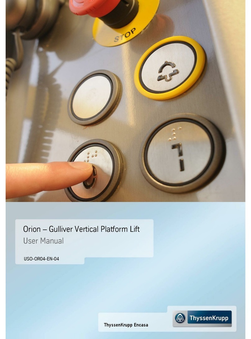
ThyssenKrupp orion User manual

ThyssenKrupp Encasa
Orion - Gulliver Vertical Platform Lift
Optional Installation Manual
INS-OPT-EN-07


01/09/2014 Orion Optional Installation Manual
1
Contents
1.'EVO' door-opener ___________________________________________________________ 2
1.1.Preliminary inspection ____________________________________________________ 2
1.2.Assembly of the mechanical components _____________________________________ 2
1.3.Electrical connections_____________________________________________________ 4
1.4.Setting the boards _______________________________________________________ 4
1.5.Final checks ____________________________________________________________ 4
1.6.Operating anomalies _____________________________________________________ 5
1.7.Connection _____________________________________________________________ 5
2.Seat ______________________________________________________________________ 6
3.Oil-heat resistance ___________________________________________________________ 6
3.1.Return to low floor procedure_______________________________________________ 7
4.Alarm system HELPY _________________________________________________________ 8
4.1.Connections ___________________________________________________________ 10
4.1.1.Verifying installation and speed programming ___________________________________ 11
4.1.2.Verifying alarm procedure __________________________________________________ 11
4.2."Autodialer" telephone combiner - Programming ______________________________ 12
4.2.1.Accessing and exiting programming __________________________________________ 12
4.2.2.Basic programming _______________________________________________________ 13
4.2.3.Advanced programming ____________________________________________________ 16

01/09/2014 Orion Optional Installation Manual
2
1. 'EVO' door-opener
1.1. Preliminary inspection
Check that the door is in
g
ood condition.
Check that the door movement is uniform and that the hinges are not
too loose.
Check that the door is plumb and in line with the horizontal upright to
which the sliding guide must be fixed.
Dismantle and remove the door suspension (figure 1A).
Disconnect and remove the return spring to close the door (figure 1B).
Figure 1 - Removal of the spring (A)
and the suspension (B) from the
door
1.2. Assembly of the mechanical components
Remove the protective cover and fix the automation to the wall, in
accordance with the measurements given in figure: refer to the hinge
axis using M6x40 screws with relative nuts and washers to fix the door-
opener.
Pierce the guide [C] and fix to the door using M5x10 screws.
In the event of an aluminium door, pierce and thread M5 the door.
Figure 2 - Fixing the door-opener
Figure 3 - Fixing the guide above the
door
A
A
B

01/09/2014 Orion Optional Installation Manual
3
If the elevator is with casin
g
to be installed internally, pierce the beam
above the door and use the spacer as shown in figure 4.
If the elevator is with casing to be installed externally, attach the three
adhesive thicknesses behind the roof covering.
Position the door-opener (to the side of the door hinges) with the upper
holes coinciding with those of the roof covering, and mark the door
structure and casing beam with a pen, at the level of the lower holes.
Drill Ø6.5 at each of the 6 marks.
Fix the door-opener with 6 M6x40 screws, 6 M6 nuts and 6 washers.
At the same time, fix the casing roof covering over the holes that remain
outside the door-opener, with 2 M6x35-TS-PEI screws.
Insert the slide [D] of the sliding arm into the guide [C]. Fix the arm to
the automation, ensuring that it inserts into the housing of the arm
supports.
Figure 4 - Spacer assembly
Figure 5 - Spacer assembly
Rest the roof coverin
g
on the door beam.
Position the door-opener (to the side of the door hinges) with the upper
holes coinciding with those of the roof covering, and mark the door
structure and casing beam with a pen, at the level of the lower holes.
Figure 6 - Fixing the roof covering
Figure 7 - Fixing the roof covering
Drill Ø6.5 at each of the 6 marks.
Figure 8 - Fixing the roof covering
Spacer

01/09/2014 Orion Optional Installation Manual
4
Fix the door-opener with 6 M6x40 screws, 6 M6 nuts and 6 washers.
At the same time, fix the casing roof covering over the holes that remain
outside the door-opener, with 2 M6x35-TS-PEI screws.
Figure 9 - Fixing the roof covering
Insert the slide [D] of the slidin
g
arm into the
g
uide [C]. Fix the arm to
the automation, ensuring that it inserts into the housing of the arm
supports.
Insert the cover [E] and the two heads [F].
Figure 10 - Accessory assembly
1.3. Electrical connections
See the electrical diagram in the Installation Manual pertaining to each system. Please remember that the packaging
also includes the manufacturer's DITEC SPRINT installation manual.
Warning! The trimmers and DIPs affect the force limiting safety function. They must be set as instructed. If not,
the modifications will not be accepted and the IN LED will flash.
-Press the OPEN key for 4 seconds (IN LED flashes);
-Set the trimmers and select the DIPs within a 5 minute time limit;
-To complete the procedure, press the OPEN key for 2 seconds or wait for the time limit to expire.
1.4. Setting the boards
Board on the actuato
r
Position the switches as shown below:
DIP1=OFF
DIP2=OFF
DIP3=OFF
DIP4=OFF (open to left)/ON (open to right)
DIP5=ON
DIP6=OFF
Bridge the safeties (G1-8, 1-9).
The TC trimmer located on the actuator is no used (and therefore should
not be adjusted).
Figure 11 - Actuator board
N.B.: each time it is turned on, the first opening or closing movement is carried out at low
speed and allows for the detection of stop levels (acquisition).
1.5. Final checks
Check that:
The switch on the actuator board is set to ON.
If the automation encounters an obstacle during closing, it detects this and re-opens.
If it encounters an obstacle during opening, it detects this and stops. In subsequent manoeuvres, the obstacle
is considered as a new stop until it is removed.
M6x40
M6x35
B
A

01/09/2014 Orion Optional Installation Manual
5
1.6. Operating anomalies
In the event of anomalies, test the door-opener installed on the door behaving in an anomalous fashion separately, as
follows:
1. Bridge pins 1 and 2 on the actuator board and check door closure.
2. Bridge pins 1 and 3 on the actuator board and check door opening.
If these tests fail, there may be an anomaly involving the actuator board. Alternatively, the anomaly is due to the EVO
panel (installed near the main electrical panel).
Warning! During system maintenance work, ALWAYS disconnect the actuator of each door,
by setting the switch to OFF. In this way, you can open the door manually without risking
damage to the actuator.
1.7. Connection
Refer to the machine wiring diagram.
The following is purely an example:
System with 2 automatic door openers, one at floor 0 and one at floor 1.
Connect the following electrical panel terminals:
Electrical panel terminal 1 -> terminal “+” on both door openers
Electrical panel terminal 2 -> terminal “-” on both door openers
Electrical panel terminal SOV -> terminal “3” on floor O door opener
Electrical panel terminal S1V -> terminal “3” on floor 1 door opener
Electrical panel terminal CL -> terminal “2” on both door openers

01/09/2014 Orion Optional Installation Manual
6
2. Seat
Position the seat in the position shown in fi
g
ure 13
and create
two 8 mm diameter holes using the frame as a template.
Figure 13
Connect the seat support corners (see fi
g
ure 14).
Figure 14
3. Oil-heat resistance
The oil heat resistance is inserted within the tank of the oil hydraulic
control panel, by removing the 1" stopper to the side of the discharge
stopper. Insert Teflon on the thread of the resistance to guarantee a
better seal.
Figure 15 - Oil-heat resistance
Warning! Insertion must be carried out with the tank empty.
Open the resistance cover by actin
g
on the 4 cross-head screws to
adjust the thermostat in order to programme the intervention
temperature desired.
Connect the 3x1.5 resistance cable to the main clamps of the electrical
panel as shown in the diagram below.
Warning: power supply 220 V.

01/09/2014 Orion Optional Installation Manual
7
When on, the red LED positioned above the resistance si
g
nals device
functioning.
Warning! Before enabling, ensure that you have filled the tank with hydraulic oil. Do not
enable the resistance dry.
Warning! The resistance remains powered if the differential switch QF1 (see electrical
diagram) is not opened.
3.1. Return to low floor procedure
To make the oil-heating resistance efficient, automatic ground floor return has been included. The
time set to enable the automatic descent is 10 minutes. Once this time has elapsed, the display will
begin to flash and emit a buzzer to warn clients that automatic down movement is about to begin.
Warning! If necessary, the manoeuvre can be interrupted by pressing the emergency STOP
or any control button.
All the systems equipped with oil-heat resistance are also equipped with sensitive edge for fit-outs
with protection, and with photocells for systems with cabins. These devices, if enabled, interrupt the
automatic descent movement. (See relative instructions and diagrams).
ELECTRICAL CONNECTION DIAGRAM RP -
NP

01/09/2014 Orion Optional Installation Manual
8
4. Alarm system HELPY
Press the button on the telephone keypad corresponding to
the symbol shown.
It indicates any phone digit: this symbol is used in the
programming description generally to indicate entries by the
operator.
Raise the inside micro telephone. You must have enabled
programming.
Raise the inside micro telephone.
Hang up the inside micro telephone.
Brackets indicate portions of code that are optional and
therefore may be omitted.
Fi
g
ure 16 - Combiner terminal board

01/09/2014 Orion Optional Installation Manual
9
A Terminal board
B JP8 Jumper (not to be removed or moved)
C Internal power connector
D Connectors for optional relay board
E Serial socket for connection to lift CPU
F Reset button
G RJ11 connector for local telephone
H RJ45 connector for module GSM200
I Battery
L Landline telephone board (optional)
M
Jumpers to be used in place of landline telephone board in
the case of connection to GSM module
N
Terminal boards for landline telephone connection or
universal GSM interface
O Connector for FlashKey and VoiceKey
P Device status and GSM field intensity indicator LED
Q Alarm end button (reset button)

01/09/2014 Orion Optional Installation Manual
10
4.1. Connections
Ensure that the jumper JP8 (see Fig.17) is in position 1-2 or
towards the outside (manufacturer's settings).
Figure 17 – Jumper JP8 position
Connect the telephone line to the LTI terminal board on the
optional board (See Fig.16 detail N).
Connect the telephone supplied (to be used for programming
of the Helpy Star module and as an entry phone) to the RG11
terminals (local telephone) (see fig 16 detail G).
Connect the power cable plug to the Schuko outlet inside the
electrical panel or cut the plug and connect it to the R N
terminal board block.
In addition, connect the battery cable inside the combiner
(red cable). Upon turning on, check that the 'Helpy Activity'
LED (see fig.16 detail P) stays on for approximately 5
seconds, before starting to flash.

01/09/2014 Orion Optional Installation Manual
11
4.1.1. Verifying installation and speed programming
Programming the telephone line
Raise the local telephone.
Key in 0# from the local telephone to enter into
programming.
After having heard 3 short tones, key in 6 6 0 .
Hang up and key in 0# from the local telephone to
exit from programming.
Programme a telephone number to request assistance:
Raise the local telephone.
Key in 0# from the local telephone to enter into
programming.
Key in 2 1 0 1 1 2 <telephone number to which the call
for assistance arrives> #
Hang up and key in 0# from the local telephone to
exit from programming.
Record the elevator identification message (max. 22
seconds). This must include all information on the
system location.
Key in 7 1 0 1 and read out the message (max 22
seconds). At the end of the message, hang up.
To hear it again: 7 2 0 1
Hang up and key in 0# from the local telephone to
exit from programming.
Make an outside call to verify that the phone line is
working
Key in 0# from the local telephone to enter into
programming.
Key in 0and comprise the telephone number to test.
To interrupt the call, hang up and key in 0# from the
local telephone to exit from programming.
Note: when you raise the local telephone, if you hear a whistle from the hands free, adjust
speaker sensitivity.“Errore. L'origine riferimento non è stata trovata.”.
Note: It is possible to carry out the programming described above without having to exit
and re-enter into programming each time
4.1.2. Verifying alarm procedure
Causing alarm procedure
Press the aid request button in the cabin and hold for
more than 2 seconds. Wait for the alarm to turn on.
Answering and resetting the alarm
Answer from the number called and:
Press 5to listen to the message or wait a few
seconds.

01/09/2014 Orion Optional Installation Manual
12
Press 0to go to hands free or wait 30 seconds.
Press 1. After approximately 2 seconds, press 9to
definitively cancel the call.
ATTENTION! If the alarm procedure cannot be interrupted (e.g. the programmed
telephone number is wrong), you will need to raise the local telephone.
and within 20 seconds, key in 0#. The key code set by the manufacturers is 0.
4.2. "Autodialer" telephone combiner - Programming
4.2.1. Accessing and exiting programming
To programme the device, you will need to enter the
programming system. To establish whether or not you
are in programming status, simply raise the micro
telephone in the telephone area:
if you have a SIGNAL INVITING YOU TO MAKE A
SELECTION (1 long tone followed by a short tone),
you are already in programming status and can
enter the desired programming codes;
if you have automatic connection to HANDS FREE,
you are not in programming status.
Accessing programming from the local phone.
Raise the local telephone. Establish connection with
HANDS FREE directly.
Key in <installer or operator key word> #. For
example, if the key word set by the manufacturer (0)
has not been changed, key in 0#.
You will hear the signal inviting you to make a
selection (1 long tone followed by a short tone).
At this point, without needing to hand the micro
telephone up again, you can enter the various
programming codes one by one (for codes, please refer
to the sections 'Basic programming' and 'Advanced
programming”'). You do not need to replace the micro
telephone between one code and another, no re-enter
the key word.
If you replace the micro telephone, by raising it once
again, you will again hear the signal inviting you to
make a selection, and will not need to re-enter the key
word in order to continue programming.
If the code programmed is correct, you obtain the
confirmation signal (3 short tones); if not, you will hear
the error signal (long, repeated tones).In this case, you
will need to replace and re-raise the micro telephone to
continue.
Exiting programming from the local phone.

01/09/2014 Orion Optional Installation Manual
13
After programming, to make the settings effective, you
will need to exit the programming status. To this end,
use the same procedure as to access programming:
Raise the local telephone. You will hear the signal
inviting you to make a selection.
Key in <installer or operator key word> #. For
example, if the key word set by the manufacturer (0)
has not been changed, key in 0#.
Establish connection with HANDS FREE directly.
4.2.2. Basic programming
The basic programming to be carried out on the device,
is as follows:
choice of telephone line type used (landline)
programming of telephone numbers for each type of
alarm
recording of identification message
clock programming
enabling the flat battery warning alarm
adjusting hands free and message volume
(optional).
Type of telephone line
Allows you to programme the type of line used.
Key in 0# from the local telephone to enter into
programming.
Key in 660
Hang up and key in 0# from the local telephone
to exit from programming.
ATTENTION! Ensure jumper JP8 is positioned towards the outside.
Programming of telephone numbers
Up to a maximum of 12 telephone numbers can be
programmed in.
To programme a telephone number to request
assistance:
Raise the micro telephone;
Key in 0# from the local telephone to enter into
programming.
Press 2 1.
Enter the position of the telephone number in the
table of 12 numbers available, from 01 to 12;
Enter a figure relative to the event:
-“1” Assistance request button;
-“2” Technological and diagnostic alarm (flat
battery)
-“3” Periodic Automatic Test call
Enter a figure relative to the type of receiver:

01/09/2014 Orion Optional Installation Manual
14
-“1” Call Centre with Ademco Contact ID
protocol;
-“2” Normal telephone utility;
-“3” Call Centre with Esse-ti protocol;
-“4” Call Centre with CLI mode.
Enter the telephone number to be called (maximum
20 digits).
Press #.
Hang up and key in 0# from the local telephone
to exit from programming.
To enter more telephone numbers, repeat the
procedure changing the position in the table. The
numbers will be called according to the position of
entry.
To delete a telephone no., key in #directly after having
keyed in the type of receiver at the point above.
E.g.:
Position Source Receiver
Number
01 Req. Assistance = 1
Normal Telephone Us. = 2
0718754213
Key in:
2 1 0 1 1 2 0 7 1 8 7 5 4 2 1 3 #
Recording / re-listening to identification message
The identification message must contain information
with regards to the location of the system, in order to
identify it unequivocally, during an alarm (this is the
message that the person answering the request for
assistance will hear).
To record the message
Raise the micro telephone;
Key in 0# from the local telephone to enter into
programming.
Press 7 1 0 1.
Record the message after the beep (max. 22 seconds);
At the end of the message, hang up.
Key in 0# from the local telephone to exit from
programming.
Note: you do not need to use all the time available. A beep will indicate that the time
available has expired.
Recording / re-listening to identification message
The identification message must contain information
with regards to the location of the system, in order to
identify it unequivocally, during an alarm (this is the
message that the person answering the request for
assistance will hear).

01/09/2014 Orion Optional Installation Manual
15
To listen to the message
Raise the micro telephone
Key in 0# from the local telephone to enter into
programming.
Press 7 2 0 1. You will hear the message.
Hang up and key in 0# from the local telephone
to exit from programming.
Clock programming
The system includes an internal clock. The date must
be programmed first, followed by the time.
Furthermore, should you re-programme the date, you
will also need to re-programme the time.
DATE
Raise the micro telephone;
Key in 0# from the local telephone to enter into
programming;
Press 3 6 ;
Enter a figure relative to the day of the week:
0=Sunday
1=Monday
2=Tuesday
3=Wednesday
4=Thursday
5=Friday
6=Saturday
Enter the date in the format day / month / year.
Example: to programme the date Tuesday 13/12/2011,
key in: 3 6 2 1 3 1 2 11
Hang up the micro telephone
TIME
Raise the micro telephone;
Press 3 5 ;
Enter the hours and minutes (from 00:00 to 23:59).
Example: to programme the time 14:50, key in 3 5 1 4
5 0
Hang up and key in 0# from the local telephone
to exit from programming.
Note: the system will automatically change with daylight saving time and vice versa.
Enabling the flat battery alarm
The system will send an alarm to the number/s
programmed when the battery is flat.
Raise the micro telephone;
Key in 0# from the local telephone to enter into
programming.
Press 5 2.

01/09/2014 Orion Optional Installation Manual
16
Enter:
0 to disable the flat battery alarm.
1 to enable the flat battery alarm.
Example: to enable the flat battery alarm, key in 5 2 1.
Hang up and key in 0# from the local telephone
to exit from programming.
Hands free
The hands free volume and microphone sensitivity of
the hands free system can be adjusted.
Raise the micro telephone;
Key in 0# from the local telephone to enter into
programming.
Key in 8 0 1.
Enter a figure relative to the speaker volume (from 1
to 4);
Enter a figure relative to the microphone sensitivity
(from 8 to 9);
Press hash #
Hang up and key in 0# from the local telephone
to exit from programming.
Note: when programming the hands free, it is turned on to allow
you to listen to the
volume and adjust accordingly.
Note: within the same programming, you can later enter more than one volume or
sensitivity value, until reaching the desired level.
Example: to set speaker volume and microphone sensitivity of the hands free system to
maximum, key in 8 0 1 4 9#
Messages
You can adjust the volume of messages:
Raise the micro telephone;
Key in 0# from the local telephone to enter into
programming.
Press 8 0 4.
Enter a figure relative to the volume level (from 1 to
4);
Press hash #
Hang up and key in 0# from the local telephone
to exit from programming.
Note: to listen to a message with the volume level set, simply press 7during
programming, after entering a figure relative to the volume level.
4.2.3. Advanced programming
The following list is of certain programming functions
that are not necessary to the use of the basic device
functions, or which may only be necessary to customise
certain features>
Recording the courtesy message.

01/09/2014 Orion Optional Installation Manual
17
Connection in the event of switchboard telephone
rather than directly to the landline.
Enabling the 'Diagnostics' technological alarm.
Recording / re-listening to the courtesy message
The courtesy message is that re-produced by the hands
free system when the corresponding button to request
assistance is pressed, in order to reassure the person
who has remained blocked in the elevator. The device
has a pre-recorded courtesy message (Italian + English)
that, if required, can be changed.
Note: should you wish to change the courtesy message, the pre-recorded manufacturer's
message cannot be recovered.
To record the courtesy message
Raise the micro telephone;
Key in 0# from the local telephone to enter into
programming.
Press 7 1 0 2.
Record the message after the beep (max. 22
seconds);
At the end of the message, hang up.
Key in 0# from the local telephone to exit from
programming.
Note: you do not need to use all the time available. A beep will indicate that the recording
time available has expired.
To listen to the courtesy message
Raise the micro telephone;
Key in 0# from the local telephone to enter into
programming.
Press 7 2 0 2.
Hang up and key in 0# from the local telephone
to exit from programming.
Connection to telephone switchboard
This allows you to indicate if the device is connected to
a telephone switchboard or directly to the landline (as
per manufacturer settings). This is necessary for the
device to properly decode the tones from the LTI
landline
Raise the micro telephone.
Key in 0# from the local telephone to enter into
programming.
Press 6 7.
Enter:
-0if the system is connected to an internal
number of a telephone switchboard
-1 if the system is connected directly to the
landline
Raise the micro telephone.

01/09/2014 Orion Optional Installation Manual
18
Hang up and key in 0# from the local telephone to
exit from programming
Note: when connected to a telephone switchboard, you will need to enter the prefix for the
switchboard landline, prior to the programmed numbers.
Technological diagnostics alarm
This allows you to enable the diagnostics procedure
and relative alarm in the event that the procedure
malfunctions.
Raise the micro telephone;
Key in 0# from the local telephone to enter into
programming.
Press 5 4.
Enter:
-0to disable the diagnostics procedure
-1to enable the diagnostics procedure
Hang up and key in 0# from the local telephone
to exit from programming.
Note: when the diagnostics alarm is enabled, upon switching the device on, it will always
carry out the diagnostics procedure.
To programme the time for the diagnostics procedure
Once enabled, the diagnostics procedure is carried out
every day at the time defined by this programming.
Raise the micro telephone
Key in 0# from the local telephone to enter into
programming.
Press 3 2.
Enter the time, in the format hours minutes, at which
the diagnostics procedure is to be carried out.
Example: to programme the diagnostics procedure for
the time of 15:20, enter: 3 2 1 5 2 0.
Hang up and key in 0# from the local telephone
to exit from programming.
Note: you must have programmed the internal clock for this to function correctly.
ATTENTION! Once programming is complete, you can exit the procedure by entering 0
# .
Other manuals for orion
1
This manual suits for next models
1
Table of contents
Other ThyssenKrupp Lifting System manuals
Popular Lifting System manuals by other brands

EKKO
EKKO EB18E Service manual

WPG
WPG MRTALP4625DC3 operating instructions

The Handy
The Handy 16007G INSTRUCTIONS, PARTS DRAWING, PART LIST

Anthony Liftgates
Anthony Liftgates ETU-20-44 Operation manual

Oshkosh Corporation
Oshkosh Corporation JLG 15BD Illustrated parts manual

Braun Corporation
Braun Corporation UVL Series NUVL604XA Service manual