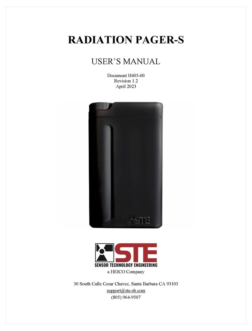
Heico STE Radiation Pager User manual

Radiation Pager User’s Manual
Copyright 2023 Sensor Technology Engineering, LLC. All rights reserved.
1
1OVERVIEW
The Radiation Pager is a compact Personal Radiation Detector (PRD) for use in the interdiction and location
of nuclear materials. It was specifically designed to be used by Customs and Border Protection agents, Law
Enforcement personnel, and First Responders. Employing a large cesium iodide crystal scintillator and a
quality photomultiplier tube for gamma radiation sensing, coupled with electronics that have been tuned
for performance and optimized for low power, the Radiation Pager is a very sensitive device with a fast
response time.Designed to be worn in a belt holster or in a
pocket, the Radiation Pager is the smallest PRD available on
the market today.
When the Radiation Pager detects radiation at levels above the
natural background, it quickly alerts the operator by flashing
a daylight-viewable LED and by either sounding an alarm or
vibrating. The operator can easily locate the radiation source
using the single digit display, the flashing indicator, or the
audible tone.
Designed from the ground up for connectivity, the Radiation
Pager employs the latest Bluetooth standards for encryption
and communication. This capability allows for real-time
streaming of radiological data to mobile device applications
and to centralized command and control networks.
The Radiation Pager is designed to withstand the rigors of
daily operation, and can be worn in an available belt holster,
or carried in a pocket. It will operate continuously for at least
3,500 hours on a single AA Lithium battery.
Table 1: Radiation Pager Specifications
Specification Description
Radiation Type
Gamma
Detector Type
Cesium Iodide Scintillator
Detector Size
5 cc
Sensitivity
2.2 cps per µR/h at Cs-137 (662keV)
Low Energy Cutoff
45keV
Integration Time
Multiple (<1, 2 Seconds)
Size
9.3 cm x 5.6 cm x 2.3 cm
Weight
150g with battery
Battery
1x AA Lithium (Li-FeS2)
Battery Life
3,500 Hours
Environmental Protection
Per ANSI N42.32 2016
Ingress Protection
IP65
Temperature Range
-25º to 50ºC
Indicators
Visible, Audible, Vibration
Compliance
ANSI N42.32 2016
Communications
Bluetooth 5.0
Figure 1: Radiation Pager Detector
Location and Center
+
Figure 2: Radiation Pager Detector
Location and Center

Radiation Pager User’s Manual
Copyright 2023 Sensor Technology Engineering, LLC. All rights reserved.
2
2OPERATION
The user interface of the Radiation Pager consists of a multicolor Indicator LED and a single digit numerical
Level Display. Together, these two indicators show the status of the instrument and communicate the
intensity of any detected gamma radiation (see Figure 2).
Figure 3: Radiation Pager User Interface
The Radiation Pager is activated by a three-position rotary Mode Switch. The middle position turns the
instrument off. By rotating the knob right, the instrument is turned on and enables the audible alarm mode.
Conversely, by rotating the knob left, the instrument is turned on and the silent (vibration) alarm mode is
enabled.
When the Radiation Pager is turned on, the middle segment of the Level Display flashes while a self-test is
conducted. At the successful conclusion of the self-test the outer segments of the Level Display will light
in a clockwise rotation for 30 seconds while the instrument measures the ambient gamma radiation
background. After the background radiation level has been measured, the Radiation Pager calculates and
briefly displays the alarm threshold value.The instrument is now ready for use. The Radiation Pager is
now measuring ambient gamma radiation and will alarm if the detected radiation exceeds the alarm
threshold.
When the Radiation Pager alarms, it flashes the Indicator LED and either vibrates or sounds an audible
tone, depending on the setting of the Mode Switch. The instrument will alarm for 14 seconds unless the
Display Button is pressed to acknowledge the alert.Once the alarm has timed out or been acknowledged,
the device enters a (silent) search mode, as described in the following paragraph. Future alarms will not
occur until radiation levels fall below the preset alarm threshold level.
At any time, the Radiation Pager may be used to search for radioactive material by pressing and holding
the Display Button. Depressing the Display Button causes the Indicator LED to flash at a duty-cycle
proportional to the level of gamma radiation detected. At low radiation levels the Indicator LED will flash
green after every 16 radiation counts. If the detected radiation increases to the point that the alarm threshold
is exceeded, the Indicator LED will flash yellow. If the Mode Switch is set to enable audio, a short tone
will also be emitted each time the Indicator LED flashes. At higher radiation levels the Indicator LED will
appear to stay on continuously. While the Display Button is depressed, the Level Display will also be
activated, and the detected radiation will be represented here numerically.
NOTE:
It is important to not turn on the Radiation Pager in the vicinity of a radiation source. This will affect
the alarm threshold calculation and will reduce the device’s sensitivity.

Radiation Pager User’s Manual
Copyright 2023 Sensor Technology Engineering, LLC. All rights reserved.
3
The Level Display provides an indication of the relative intensity of the detected radiation on a scale of
zero through nine. Each number indicates a radiation intensity of roughly twice the previous value (i.e. a
level 4 is about twice the radiation intensity of a level 3).
Table 2 shows the Level Display values and their corresponding exposure rates in micro-Roentgen per hour
(µR/h). Above the exposure rates shown here, the unit will continue to display a 9.
At approximately 6,000 µR/hr. the Indicator LED will be illuminated red, which indicates that the device
is reading gamma radiation above its normal operating range, and that radiation levels may have reached a
level hazardous to the operator.
3MOBILE APPLICATION
The Radiation Pager is equipped with a Bluetooth communication capability allowing the user to connect
with either an iOS (Apple) or Android-based mobile device to:
1. Register alarms for Gamma radiation
2. View exposure and dose equivalent estimates
3. View the historical data collected
4. View live data streaming from the Pager
5. View map location with path trace
6. Download/transfer data files
Bluetooth operation can be used in parallel with the Radiation Pager display.
1Exposure rates listed here are indicative of the average rate represented by level reading shown.
Level Exposure Rate1
µR/h at Cs-137 (662keV)
1
10
2
25
3
60
4
140
5
300
6
600
7
1,400
8
3,000
9
6,000 +
Table 2: Exposure Rate Table

Radiation Pager User’s Manual
Copyright 2023 Sensor Technology Engineering, LLC. All rights reserved.
4
The application can be found on the Apple store and Google Play store (Android) – search for Sensor
Technology Engineering
STE
When opening the application, the following notices (or similar) will appear:
Message on Mobile Device
Recommended Action
“STE” would like to send you notifications
Click “Allow”
Allow “STE” to use your location
Click “Allow While Using App”
“STE” would like to use Bluetooth
Click “OK”
This will enable full functionality.
CONNECTION AND USAGE
Open the application and you will see the devices screen (Screen 1). Bright or Dark mode selection is
performed from the hamburger menu shown in Screen 2. Bright Mode and Dark Mode options are shown
in Screen 1 and Screen 4.
Screen1 Screen 2 Screen 3 Screen 4

Radiation Pager User’s Manual
Copyright 2023 Sensor Technology Engineering, LLC. All rights reserved.
5
Turn on the Radiation Pager (if already on, turn off for 5 seconds and then on again). In the two-minute
period immediately after the Radiation Pager is turned on, it will be available to connect with the mobile
device. The Radiation Pager Bluetooth module will emit a signal that will be detected by the mobile app.
This signal will terminate after two minutes if a mobile device is not connected with the Radiation Pager.
For EOD (Explosive Ordinance Disposal) units it is often preferred to NOT have Bluetooth signals active
in the environment, so do not connect a mobile device in the first two minutes and the Radiation Pager will
not emit a signal until turned off and on again. Note that only one mobile device can be paired with a
detector at any given time.
Click “Add a Device”. Once the Radiation Pager is “ON” the app will recognize it and will show the device
image and approximate distance from the mobile device. In an environment where there may be more than
one Radiation Pager being activated this allows the user to select the closest device. There may also be
other STE detectors in the area as shown in Screen 5.
Screen 5 Screen 6

Radiation Pager User’s Manual
Copyright 2023 Sensor Technology Engineering, LLC. All rights reserved.
6
Once the Radiation Pager is selected the gamma screen will display. Please remember that the Radiation
Pager is still in its warmup mode, performing the background calculation and has yet to calculate the alarm
trip point. This can take up to 30 seconds.
When complete, the display should be similar to Screen 6. The green line is the alarm trip point. The
graph is 2 minutes in duration (waterfall from right to left) updating twice per second. If a radiation source
is brought close, the system will alarm as shown in Screen 7. The user can also select the units desired in
terms of dose equivalent or in CPS (counts per second) – Screen 8.
Screen 7 Screen 8

Radiation Pager User’s Manual
Copyright 2023 Sensor Technology Engineering, LLC. All rights reserved.
7
The next menu item is “Dosage” shown in Screen 9. This measures the cumulative dose measured by the
detector during a given period (as measured by the horizontal axis). For higher exposure rates the graph
can be seen to have a steeper gradient as the user experiences more radiation per unit time. This graph will
always continue to read and accumulate dose even from background radiation alone.
Screen 9

Radiation Pager User’s Manual
Copyright 2023 Sensor Technology Engineering, LLC. All rights reserved.
8
DATA EXPORT
Click on “Alarms” and you will see Screen 10. This details every alarm “event” that has occurred.
An event is defined as beginning the instant the detector measures radiation above threshold trip
point until the time that it drops below threshold. The resulting dataset will appear as shown on the
screen including, date, start time, end time, detector serial number, maximum exposure rate, exact
location and physical address. Each “event” will be numbered in sequence as shown in the screen
with the most recent event at the top
To export all of the event data, click “Export All Data” and you will see the typical selection of
options as shown in Screen 11. The data is formatted in a CSV file and can be transmitted as
preferred.
Screen 10 Screen 11

Radiation Pager User’s Manual
Copyright 2023 Sensor Technology Engineering, LLC. All rights reserved.
9
In the “Settings” menu the user has the ability to delete all the data on the mobile device from a
given detector as shown in Screen 12 and Screen 13.
Screen 12 Screen 13

Radiation Pager User’s Manual
Copyright 2023 Sensor Technology Engineering, LLC. All rights reserved.
10
Map
The user also has the ability to see a map of current location (Screen 14) as well as a “trace history”
of where the detector has been carried (Screen 15). Click on the globe icon on the top right of the
screen and the map will open and zoom into the current location. When the detector is moved it will
appear as a trace on the map. If the user zooms into the map the trace will resolve into a series of
dots (Screen 16). If the dot (and trace) is green, the radiation level is below the trip point. If the
detector measures radiation and sounds an alarm then the dots/trace will appear yellow/orange/red
depending on the alarm level (yellow low alarm level, red high alarm level). The exact location
(address and map coordinates) will be recorded in the Alarms data.
Screen 14 Screen 15 Screen 16

Radiation Pager User’s Manual
Copyright 2023 Sensor Technology Engineering, LLC. All rights reserved.
11
On the map, the “document stack” icon (Screen 17marked with a red arrow) allows the user to
access different map views (Screen 18) as desired (e.g., topology, google satellite etc.). As with
most mobile devices, the user can screenshot maps to send directly to others for rapid coordination.
Screen 17 Screen 18

Radiation Pager User’s Manual
Copyright 2023 Sensor Technology Engineering, LLC. All rights reserved.
12
4BATTERIES
The Radiation Pager uses one AA Lithium (Li-FeS2) battery. In routine operation with few alarms and low
Bluetooth usage, one such battery will power the unit continuously for 3,500 hours.
A low battery condition is indicated when the Level Display briefly flashes an ‘L’ every 20 seconds. This
indication will be accompanied by a brief ‘chirp’ when the instrument is in audible alarm mode.
To change the battery on the Radiation Pager, remove the battery cover using a coin as a tool. The old
battery can then be removed, and a new AA Lithium battery can be installed. Care should be taken to
ensure that the new battery is installed in the correct orientation (positive terminal first – see Figure 4).
Ensure that the battery cover O-ring and the mating surface on the Radiation Pager enclosure are clean,
insert the battery cover, and use a coin as a tool to screw it in place – do not overtighten.
Figure 4: Unscrewing (left) and Removing the Battery Cover (center), and Replacing the Battery (right)
5MAINTENANCE AND CALIBRATION
The Radiation Pager does not require periodic maintenance or factory calibration. It is good practice,
however, to occasionally verify the functionality of the instrument against a small, low energy gamma
check source. The preferred source is one µCi of Americium (Am-241). This source will be detectable at
about three inches from the sensor. The alarm level will be in the range of 3-6 when the instrument is placed
in contact with the check source.
If the Radiation Pager doesn’t power up, shows a solid middle element on the Level Display, or false alarms
frequently, then it needs to be sent back to Sensor Technology Engineering for service.
WARNING - HIGH VOLTAGE:
Do not open the Radiation Pager enclosure - there are no user serviceable parts inside.
NOTE:
Alkaline batteries should not be used in the Radiation Pager due to the risk of leakage over long periods
of time. Alkaline battery leakage has historically been a leading cause of Radiation Pager failure, and
damage from the use of Alkaline batteries is not covered by the Radiation Pager limited warranty.

Radiation Pager User’s Manual
Copyright 2023 Sensor Technology Engineering, LLC. All rights reserved.
13
6REFERENCE
Tables 3 and 4, below provide a quick guide as to the various Radiation Pager states and indications.
Table 3: Radiation Pager Indicator LED States
Indication Color Description Explanation
Blue
Flashing (Single) Bluetooth communications ready to pair
Flashing (Double) Bluetooth is paired
Green Flashing (With Display Button Pressed) Relative indication of gamma radiation
level, below alarm threshold
Yellow
Flashing (With Display Button Pressed) Relative indication of gamma radiation
level, above alarm threshold
Flashing with Audible or Vibration
Alarm
Alarm. Indicates that a gamma radiation
source is present.
Red Solid, Accompanied by a ‘9’ on the
Level Display
Over-r
ange indication. Indicates a
gamma radiation exposure rate of 6,000
µR/hr or greater. Follow departmental
procedures for operating in elevated
gamma radiation environments.
Table 4: Radiation Pager Level Display States
Indication Description Explanation Action
Rotating Measuring radiation and
calculating background level None
Flashing Power up system tests being
performed None
Solid2System tests failed
Try replacing the battery; if
that
fails, return the unit for
factory service
Flashing (Every 20
Seconds) Low battery Replace the battery
Solid Indication of the relative gamma
radiation level Locate the radiation source
2The middle element of the Level Display will be briefly illuminated solid at the completion of a successful self-test. This should
not be cause for concern. If the unit fails self-test, the middle element will be displayed solid indefinitely.
Table of contents
Other Heico Security Sensor manuals
Popular Security Sensor manuals by other brands

Mier products
Mier products DA-600 manual

Pilz
Pilz PSEN opII mirror column Series operating manual

Honeywell
Honeywell MeshGuard LEL IR user guide

Honeywell
Honeywell C7061A1020 Product handbook

Bosch
Bosch TriTech+ ISC-PDL1-WA18G installation instructions

Teledyne
Teledyne 340CF ELSD Installation and operation guide