HEIDENHAIN IK 215 User manual

Betriebsanleitung
Operating Instructions
IK 215
8/2009

2
Allgemeine Informationen
Die Interfacekarte IK 215 ist eine PCI-Bus-Einsteckkarte für IBM-PCs und 100% Kompatible. An die IK 215
kann ein HEIDENHAIN-Messgerät mit EnDat 2.1 oder EnDat 2.2 Schnittstelle angeschlossen werden.
Für den Betrieb der IK 215 mit Messgeräten anderer Hersteller trägt der Anwender jegliches Risiko.
Das EnDat-Interface bietet die Möglichkeit, im Speicherbereich des Kunden maschinen- oder
anlagenspezifische Daten zu hinterlegen. Diese Daten können sicherheitsrelevante Informationen
beinhalten. Bitte achten Sie daher im Servicefall darauf, dass dieser Speicherbereich angeglichen wird.
Wird dies nicht beachtet, können Maschinen- oder Personenschäden die Folge sein.
Gefahr für interne Bauteile!
Die Vorsichtsmaßnahmen bei der Handhabung elektrostatisch entladungsgefährdeter Bauelemente
(ESD) nach DIN EN 100015 beachten. Als Transport-Verpackung nur antistatisches Material verwenden.
Beim Einbau ausreichende Erdung des Arbeitsplatzes und der Person sicherstellen.
Spannungsversorgung des PC
Die IK 215 darf nur in PCs betrieben werden, die für die +12 V Spannungsversorgungsleitung einen
Mindeststrom von 1,5 A garantieren, da sonst bei einem Kurzschluss am Messgeräteingang der PC
beschädigt werden kann.
Systemvoraussetzungen:
¬Windows XP/2000
¬50 MB freier Speicher auf der Festplatte (bei Verwendung der ATS-Software)
¬PCI Local Bus gemäß Spezifikation Rev 2.1
Allgemeine Informationen Deutsch

3
Steckerbelegungen der IK 215 Anschluss für das Messgerät
Der Anschluss des Messgeräts erfolgt über den Messgeräteingang X1.
Die 15-polige Sub-D-Buchse ist wie folgt belegt:
Spannungsversorgung Inkrementalsignale absolute Positionswerte
4 12 2 10 6 1 9 3 11 14 7 5 13 8 15
UPSensor
UP0 V Sensor
0 V Innen-
schirm A+ A– B+ B– R+ R– DATA DATA CLOCK CLOCK
Schirm liegt auf Gehäuse; UP= Spannungsversorgung
Sensor: Die Sensorleitung ist im Messgerät mit der jeweiligen Spannungsversorgung verbunden. Die am Messgerät anliegende Spannung lässt
sich über die Sensorleitungen prüfen und ggf. nachregeln.
Nichtverwendete Pins oder Litzen dürfen nicht belegt werden!
Die Spannungsversorgung des Messgeräts (Pin 4) ist per Software einstellbar und schaltbar. Es ist
darauf zu achten, dass die korrekte Versorgungsspannung für das Messgerät eingestellt wird, da
ansonsten das Messgerät beschädigt werden kann. Desweiteren ist zu beachten, dass das Messgerät
nur bei abgeschalteter Versorgungsspannung ein- und ausgesteckt werden darf.
Deutsch IK 215

4
Anschluss für externe Funktionen
Für externe Funktionen ist eine 4-polige Buchse vorhanden, über die die Messwertaufzeichnung
von außen gesteuert werden kann. Der dafür benötigte Stecker kann bei HEIDENHAIN unter der
Ident-Nr. 282 168-01 bestellt werden.
Die Signale sind wie folgt zugeordnet (Sicht von außen auf die Buchse):
1
4
3
2
Pin Belegung
1 Eingang: Einspeicherimpuls
2 Ausgang: Synchronisationsimpuls
3 Ausgang: MSB des Positionswertes (Singleturn) (nur bei EnDat)
4 GND
Spezifikation des PCI-Bus
Spezifikation PCI Local Bus Specification Rev. 2.1
Spannungsversorgung +5 V ± 5%
+12 V ± 5%
–12 V ± 5%
Leistungsaufnahme ca. 4 Watt, ohne Messgeräte
Abmessungen ca. 100 x 190 mm
IK 215 Deutsch

5
Spezifikation der 1-VSS-Inkrementalsignale
Signalamplituden A, B (0°, 90°) 0,6 VSS bis 1,2 VSS
Signalpegel für Fehlermeldung †0,22 VSS
Maximale Eingangsfrequenz 400 kHz
Kabellänge zum Messgerät max 150 m
Spezifikation der bidirektionalen Schnittstelle EnDat
Eingangsbaustein Differenzleitungsempfänger (z.B. SN65ALS176D)
Eingangssignale Differenzsignale nach RS 485
Abschlusswiderstand 121 −
Maximale Taktfrequenz 8000 kHz für EnDat-Interface
Kabellänge zum Messgerät max. 150 m
Deutsch EnDat 2.2-Schnittstelle

6
Inbetriebnahme der IK 215
Installation der IK 215
Gefahr durch elektrostatische Aufladung!
Beim Einbau ausreichende Erdung des Arbeitsplatzes und der Person sicherstellen.
Da jegliche Software, die die IK 215 benötigt, ohne IK 215 nur eingeschränkt lauffähig ist, empfiehlt es
sich, die IK 215 in den PC einzubauen, bevor die Software installiert wird. Dazu muss die Spannungs-
versorgung vom PC getrennt werden, anschließend ist das Gehäuse zu öffnen und die Slot-Blende eines
freien PCI-Steckplatzes zu entfernen. Die IK 215 ist nun in den PCI-Steckplatz einzuschieben und die
Blende mit dem PC-Gehäuse zu verschrauben. Abschließend ist das PC-Gehäuse zu schließen, das
Netzkabel wieder zu verbinden und der PC einzuschalten.
Installation der Software Die Installationshinweise sind auf der CD hinterlegt. Bitte lesen die Hinweise vor der Installation genau
durch.
Verbindung zum Messgerät herstellen
Das Anstecken bzw. Abziehen des Verbindungskabels zwischen Messgerät und IK 215 darf nur im
spannungsfreien Zustand erfolgen. Ansonsten können Messgerät und IK 215 beschädigt werden.
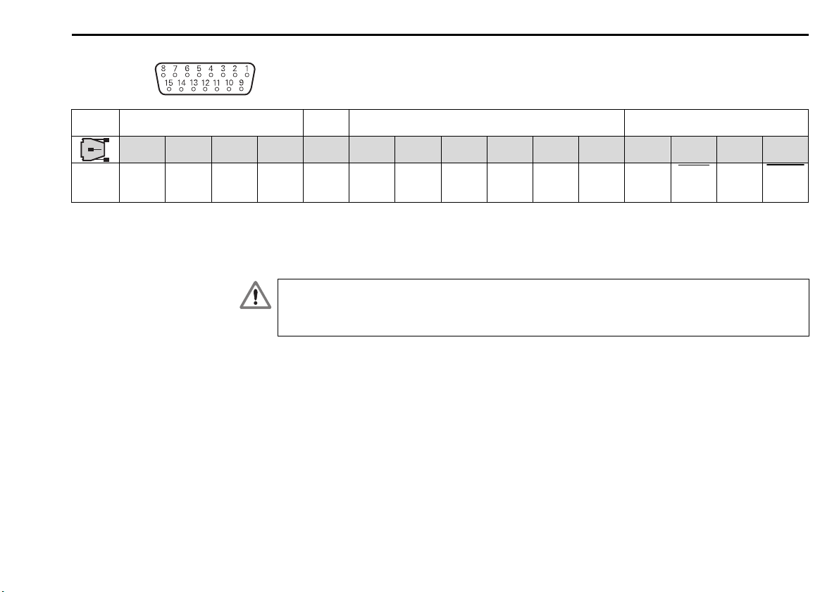
Prüfen Sie, ob das Verbindungskabel zwischen Messgerät und IK 215 korrekt verdrahtet ist. Die
Anschlussbelegung des Messgeräts ist in den Technischen Daten hinterlegt. Die Anschlussbelegungen
der Verbindungskabel sind dem Katalog zu entnehmen. Ein falsch verdrahtetes Verbindungskabel kann
das Messgerät und die IK 215 beschädigen.
Inbetriebnahme der IK 215 Deutsch

7
General Information
The IK 215 interface card is an PCI bus expansion board for IBM and 100% IBM-compatible PCs.
One HEIDENHAIN encoder with EnDat 2.1 or EnDat 2.2 interface can be connected to the IK 215.
Encoders from any other manufacturers are connected with the IK 215 at the user‘s own risk.
The EnDat interface permits the user to save data on his specific machine or system in the memory
area for customers. The data can contain information relevant to machine safety. Therefore, in case of
servicing please ensure that this memory area is updated. Noncompliance with this warning could
result in damage to the machine or in personal injury.
Danger to internal components!
When handling components that can be damaged by electrostatic discharge (ESD), follow the safety
recommendations in EN 100015. Use only antistatic packaging material. Be sure that the work station
and the technician are properly grounded during installation.
Power supply of the PC
The IK 215 may be installed only in PCs that guarantee a minimum current of 1.5 A for the +12 V power
supply line. Otherwise, the PC could be damaged in the event of a short circuit at its encoder input.
System requirements:
¬Windows XP/2000
¬50 MB free memory on the hard disk (when using the ATS software)
¬PCI local bus according to Spec. Rev. 2.1
English General Information

8
Pin layout of the IK 215 Connection for the encoder
The encoder is connected to the input X1.
The pin layout of the 15-pin D-sub female connector is as follows:
Power supply Incremental signals Absolute position values
4 12 2 10 6 1 9 3 11 14 7 5 13 8 15
UPSensor
UP0 V Sensor
0 V Internal
shield A+ A – B+ B – R+ R – DATA DATA CLOCK CLOCK
Shield on housing; UP= Power supply
Sensor: The sensor line is connected in the encoder to the respective the power supply. The voltage at the encoder can be tested over sensor
lines and, if required, adjusted.
Vacant pins or wires must not be used!
The power supply of the encoder (pin 4) is adjustable and switchable per software. To avoid damage to
the encoder, ensure that the correct supply voltage is selected. Remember also that the encoder must
not be connected or disconnected while under power.
IK 215 English

9
Connection for external functions
For external functions, a 4-pin female connection is available through which the recording of measured
values can be externally controlled. The required connector can be ordered from HEIDENHAIN under the
part number 282 168-01.
The signals are arranged as follows (view of the connection from outside):
1
4
3
2
Pin Assignment
1 Input: Latch pulse
2 Output: Synchronization pulse
3 Output: MSB of the position value (singleturn) (only with EnDat)
4 GND
Specification of the PCI bus
Specification PCI local bus Spec. Rev. 2.1
Power supply +5 V ± 5%
+12 V ± 5%
–12 V ± 5%
Power consumption Approx. 4 watts, without encoders
Dimensions Approx. 100 x 190 mm
English IK 215

10
Specification of the 1 VPP incremental signals
Signal amplitudes A, B (0°, 90°) 0.6 VPP to 1.2 VPP
Signal level for error message †0.22 VPP
Maximum input frequency 400 kHz
Cable length to encoder Max. 150 m
Specification of the bidirectional EnDat interface
Input component Differential line receiver (e.g. SN65ALS176D)
Input signals Differential signals to RS 485
Terminating resistor 121 −
Maximum clock frequency 8000 kHz for EnDat interface
Cable length to encoder Max. 150 m
EnDat 2.2 Interface English

11
Initial Operation of the IK 215
Installing the IK 215
Danger of electrostatic discharge!
Be sure that the work station and the technician are properly grounded during installation.
Since any software that requires the IK 215 cannot provide all functions without it, HEIDENHAIN
recommends installing the IK 215 in the PC before the software. To do so, first separate the PC from its
power supply, then open the housing and remove the slot cover in front of a vacant PCI slot. Plug the IK
215 into the PCI socket and then reinstall the slot cover in the PC housing. Finally, reclose the PC
housing, reconnect the power cord, and switch on the PC.
Installing the software The installation instructions are saved on the CD. Please read these instructions carefully before
installation.
Setting up a connection to the encoder
The cable between the encoder and IK 215 must not be connected or disconnected while under power.
Otherwise the encoder and IK 215 might be damaged.
Check whether the cable between the encoder and IK 215 is correctly wired. The pin layout of the
encoder is included in the specifications. The pin connections of the connecting cables are described in
the catalog. An incorrectly wired connecting cable might damage the encoder and IK 215.
English Initial Operation of the IK 215

DR. JOHANNES HEIDENHAIN GmbH
Dr.-Johannes-Heidenhain-Straße 5
83301 Traunreut, Germany
{+49 8669 31-0
|+49 8669 5061
E-mail [email protected]
Techn cal support |+49 8669 32-1000
Measur ng systems {+49 8669 31-3104
E-mail [email protected]
TNC support {+49 8669 31-3101
E-mail [email protected]
NC programm ng {+49 8669 31-3103
E-mail [email protected]
PLC programm ng {+49 8669 31-3102
E-mail [email protected]
Lathe controls {+49 8669 31-3105
E-mail [email protected]
www.he denha n.de
549 369-91 · Ver00 · 5 · 8/2009 · S · Printed in Germany
Table of contents
Languages:
Other HEIDENHAIN Computer Hardware manuals
Popular Computer Hardware manuals by other brands

Avaya
Avaya XM24 Expansion Module installation instructions

OpenVox
OpenVox IPC120 user manual

Huananzhi
Huananzhi Q170 user manual

Cypress Semiconductor
Cypress Semiconductor CY7C0241AV Specification sheet

Maxim Integrated
Maxim Integrated MAX32560 EMV DTE user manual

SeaLevel
SeaLevel Ultra-SIO 3089 user manual