HEIDENHAIN IK 5000 QUADRA-CHEK User manual

IK 5000
QUADRA-CHEK
OEM
Software Version
3.0.x
9/2013
Quick Reference Guide
Guide de Démarrage rapide

IK 5000 QUADRA-CHEK
Card, flyout and connector configurations
IK 5294
X, Y, Z
Axis encoders
and foot switch
44 pin edge
Q Axis
Encoder
30 pin header
+5V, +12V
Ground
4 pin header
E
A
C
H
44 pin
30 pin
G
PC Motherboard
Connections
IK 5294 Card
26 pin
PCI Bus
Slot connector
681041-02
(Foot switch)
J
IK 5294
Metrology Computer
IK 5294 Card
540541-24
540541-05
( 1 Vpp)
( TTL)
( 1 Vpp)
( TTL)
540550-40
540550-10
1 Vpp/ TTL
1 Vpp/ TTL
1 Vpp/ TTL
1 Vpp/ TTL

1
IK 5000 QUADRA-CHEK English
Installation and Setup
For detailed description, see www.heidenhain.de
Before Power up
Caution
• Mounting and commissioning is to be
conducted by a specialist in electrical
equipment and precision mechanics
under compliance with local safety
regulations.
• Do not engage or disengage any
connections while under power.
• The drive must not be put into
operation during installation.
Danger of electrical shock!
• Never work in an open enclosure
when power is connected.
Disconnect the power cable before
opening the enclosure.
• Never use 3-wire to 2-wire adapters
or allow the ground connection to
the IK 5000 PC to be interrupted or
disconnected.
Caution
Do not connect encoders or other
equipment to the IK 5000 when the
power is on.
Safety Considerations
Accepted local safety regulations
must be followed when operating
the IK 5000. Failure to observe these
regulations could result in damage to
the equipment, or injury to personnel.
It is understood that safety rules within
individual companies vary. If a conflict
exists between the material contained
in this guide and the rules of a company
using this system, the more stringent
rules should take precedence.
Using this Guide
This guide includes installation and
setup instructions for all standard
IK 5000 products, therefore only certain
of the instructions will apply to your
specific system. Follow the installation
and setup instructions in the order
presented, and skip steps that do not
apply to your system.
PC cards, Flyouts and
Connectors
Diagrams on the preceding pages
show IK 5000 PC cards, flyouts and
connectors for all standard IK 5000
systems. As shown in the diagrams,
some external connections are made
directly to the IK 5000 PC card, others
are made to the card though flyout
connectors.
While certain PC cards, flyouts and
connectors are common to multiple
IK 5000 products, others are unique
to specific members of the IK 5000
product family.The IK 5494-3D PC card,
flyout for K and M connectors and a
typical PC connector configuration are
shown below as examples.
PC card for IK 5494-3D
K and M flyout for IK 5494-3D
Typical PC card and flyout
connectors at the rear of a PC
IK 5000 connectors are shown in the
diagrams of preceding pages. Connector
pin wiring is shown at the end of this
guide.
Connector Description
AX,Y and Z Encoder and foot
switch inputs
BX,Y and Z axis CNC control
outputs
CIK 5000 card connection to
Flyout connectors H and J
DIK 5000 card connection to
Flyout connector K
EIK 5000 card power connector
FIK 5000 card connection to
Flyout connector N
GIK 5000 card PCI connector to
PC motherboard
HQ axis encoder input
JQ axis CNC control output
KVideo light outputs
MTouch probe input
NCamera zoom control output
PComparator light source input
for optical edge detection
RComparator screen sensor
input for optical edge detection
TOptical daughter board optical
cables through connectors P and
R to the comparator light source
and screen sensor
VTP200 daughter board
connection to flyout
connector M
WRS-232 PC motherboard
connector
Note
The instructions in this Quick Reference
Guide are intensionally brief. Refer
to the IK 5000 OEM Setup Guide
at www.heidenhain.de for detailed
instructions.
Very important
Please note
For your information

2
Software Setup
Certain essential operating parameters
of the IK 5000 must be configured prior
to using the system for the first time.
Many additional factory default
parameters can be changed later to
accommodate specific application
requirements, however, the essential
settings discussed in subsequent pages,
combined with the factory defaults
will be adequate to begin operating
standard IK 5000 systems. Please refer
to the IK 5000 OEM Setup Guide
at www.heidenhain.de for details
regarding all setup parameters for the
standard IK 5000 product family.
Additional software drivers will need to
be installed for systems that utilize USB
cameras for video edge detection.
Follow the installation and setup
instructions in the order presented,
and skip steps that do not apply to
your system. Instructions will be found
under headings that indicate the target
systems:
• All Systems indicates instructions for
all IK 5000 systems
• CNC Included indicates instructions
for systems that include CNC control
• Optical Edge Included indicates
instructions for systems that include
optical edge detection
• Video Edge Included indicates
instructions for systems that include
video edge detection
• Touch Probe Included indicates
instructions for systems that include a
touch probe
All Systems
1. Turn the PC power on
Launch the PC operating system.
2. Install the video camera driver
If your system utilizes a digital video
camera, follow the manufacturer’s
instructions to install and test the video
camera. Restart your system after the
installation.
3. Install the IK 5000 software
Insert the IK 5000 CD into the CD ROM
drive and follow the instructions shown
on the screen to install the IK 5000
software.The PC will restart after the
installation.
Note
Plug the cables into IK 5000 connectors
C, D and F at the top of the card with
the cable connector flanges facing
down.
Flyout cable connection to IK 5000
PC card
Flyouts connected to IK 5000 PC
card connectors C, D and F
7. Close the PC enclosure
Confirm that all cards, cable connections
and flyouts are securely fastened and
then replace the PC covers or panels.
8. Connect all other system hardware
Refer to the Card, Flyout and
Connector Configuration diagram
for your specific system shown earlier
and connect all other system hardware
to the IK 5000 card, flyouts and PC
motherboard connectors.
9. Connect the PC power cable
Confirm that the PC power switch is in
the OFF position and then connect the
PC power cable to the PC and then to
the power source.
Caution
Attach to the power source through a
high-quality electrical surge suppressor
to prevent damage to the PC and
IK 5000 card due to power line
transients.
PC Card and Flyout installation
The installation of the IK 5000 PC card
and associated flyouts requires only
a screwdriver and personal antistatic
protection.
Danger of electrical shock!
Never work in an open enclosure
when power is connected. Disconnect
the power cable before opening the
enclosure.
Caution
Attach antistatic protection such as a
foot strap or wristband before installing
IK 5000 hardware into your PC to
prevent damage to circuit devices.
1. Disconnect power from the PC
2. Open the PC enclosure
Remove any covers or panels to
gain access to the motherboard PCI
expansion slots.
3. Remove flyout blanks
Refer to the Suggested PC Card and
Flyout Placement diagram near the end
of this guide and remove flyout blanks
to accommodate the IK 5000 card and
flyouts provided for your system.
Note
The card and flyout locations apply to
most PCs with multiple expansion slots.
Your PC might require different card or
flyout positioning.
4. Install the IK 5000 card
Carefully plug the IK 5000 card into a
PCI slot location. Limit card handling to
the card edges as much as possible and
secure the card with a bracket screw.
5. Install flyouts
Install the flyouts for your system into
the appropriate locations and secure
with bracket screws.
6. Connect flyout cables to the card
Plug the internal flyout cables and power
cable for your IK 5000 application into
the appropriate card connectors. Refer
to the Card, Flyout and Connector
Configuration diagrams on earlier
pages for the correct cable connections.
Installation and Setup

3
• When a few full limit-to-limit motions
have been completed without scale
errors, click the OK BUTTON to return
to the Custom Encoder Setup screen.
• Click the PHASE DISPLAY TYPE
BUTTON to display the combined
encoder output phases as an
ellipsoidal pattern.
Encoder phase output
• Move an encoder slowly between
its limits of travel and evaluate the
resulting pattern. A circle will be
shown when the encoder phase
amplitudes are equal. If the pattern
displayed is not circular, the reader
head will need to be realigned and
the encoder recalibrated from the
beginning.
• The brightness of the pattern can
be changed for better evaluation.
Click the PERSISTENCE BUTTON to
display a data field. Enter a value from
1 to 1000. Higher numbers result in
brighter patterns.
• Close the Encoder Setup program and
center the stage axes.
7. Launch the IK 5000 software
Click START/PROGRAMS/QC5000/
QC5000 to launch the IK 5000 software.
You will be asked if you wish the
program to create:
• A Supervisor settings file
• A user settings file
AnswerYES to both questions.
Installation and Setup
• To limit stage travel, click the LIMIT
SWITCH SETUP BUTTON. The
Limit Switch Setup screen will be
displayed.
• Enter limit switch active levels into
the ACTIVE fields for each axis
(0=low, 1=high).
• Check the ENABLE BOX for each axis
and then click the APPLY and CLOSE
BUTTONS.
All systems with analog encoders
Encoder calibration is identical for
current and voltage devices.To calibrate
an analog encoder:
• Select the desired axis, confirm
that the correct Axis Scale Type
is selected and click the WAVE
DISPLAY TYPE BUTTON.
• Click the CALIBRATE BUTTON. You
will be instructed to move the axis.
• Begin moving the axis in slow, gradual
back and forth or up and down
motions, and click the OK BUTTON.
The sine wave output of the analog
encoder will be displayed. After a
moment the changing encoder output
count value and number of count
errors will be shown.
Encoder wave output
• Continue moving the encoder slowly
between the limits of motion until a
few full limit-to-limit motions have
been completed.
Note
Wave imperfections won’t necessarily
affect the accuracy of measurements.
However, erratic frequency or amplitude
variations or high noise can cause
inaccuracies. If any erratic output is
noted, or if scale errors appear, check
the encoder head mounting, alignment
and wiring for problems.
4. Launch IK 5000 Encoder Setup
Click START/PROGRAMS/QC5000/
ENCODER SETUP.The Custom Encoder
Setup screen will be displayed.
Encoder Setup screen
5. Select axis encoder types
Click an AXIS RADIO BUTTON and then
click an AXIS SCALE TYPE BUTTON to
select an axis encoder type. Continue
until all axis encoder types are identified.
Note
TTL encoders do not require calibration.
Skip the encoder calibration instructions
for axes utilizing TTL encoders and
proceed to step 7.
6. Calibrate analog encoders
• Analog encoder calibration must
be performed for manual and CNC
systems.
CNC systems with analog encoders
If your system includes CNC, click the
JOYSTICK SETUP BUTTON.The Joystick
Setup screen will be displayed.
Caution
You must limit stage motion before
calibrating analog encoders in CNC
systems to prevent personal injury or
damage to the equipment.
• To limit stage velocity, enter low
values for each axis into the SPEED
fields:
• Normal Speed
• Fine Speed
• Check the ENABLE BOX for each axis.
• Move the joystick through its entire
range of motion for all axes, click the
APPLY CAL, APPLY SETTINGS and
CLOSE BUTTONS.

4
Option check box selections for standard systems include:
System Option Description
All Systems NLEC Nonlinear error correction - Optional
3DErrorComp Volumetric error correction - Optional
Profile Measurements compared to drawing
profiles - Optional
Temperature Temperature compensation - Optional
MultipleRefFrames Multiple reference frames - Optional
CNC CNC CNC control - Required
Rotary Q-axis CNC - Optional
Zoom Camera zoom control - Optional with VED
AutoFocus Camera autofocus - Optional with VED
XYManualZCNC CNC for only Z axis - Optional
XYCNCManualZ CNC for only X andY axes - Optional
SeparateJoystickSetup PID for X,Y and Z axis joysticks - Optional
Crosshairs StandAloneCrosshair Systems with only crosshairs - Required
DisplayQ Display Q-axis values - Optional
DisplayZ Display Z-axis values - Optional
Optical Edge OE Optical edge detection - Required
DisplayQ Display Q-axis values - Optional
Video Edge VED Video edge detection - Required
Light Video light control - Optional
DX9 Digital camera input - Optional
DisplayQ Display Q-axis values - Optional
DisplayZ Display Z-axis values - Optional
Touch Probe Full3D Measure X,Y and Z values - Required
ContactProbes Touch probe input - Required
ProbeRack Probe selection control - Optional with CNC
DisplayQ Display Q-axis values - Optional
DisplayZ Display Z-axis values - Optional
8. Enable options for your system
Caution
Setup parameters control the operation
of the IK 5000 and are password-
protected. Only qualified personnel
should be given password access to
setup screens.
• Click the TOOLS/OPTIONS/
SUPERVISOR TAB to display the
supervisor Password field.
Options screen and Supervisor
password field
• Enter OPTIONS into the Password
field to display Factory Options.
Factory Options screen
• Check the FACTORY OPTIONS
BOXES required for your system.
Leave boxes that do not apply to your
system unchecked. Check box items
for standard systems are shown at
the right.
Factory options are required or optional
and most can be enabled without
additional charge. However, certain
options require licensing. In these cases
you will be prompted for an activation
password upon restarting the
IK 5000.
• If you are prompted, call Heidenhain
customer support with the System
ID number and you will be given an
activation password.
• Click OK to save settings.The IK 5000
program will shut down.
• Launch the IK 5000 program again,
clickTOOLS/OPTIONS and then enter
the supervisor PASSWORD.
Installation and Setup
9. Set machine zero
A machine zero is established by the
system each time power is applied.
Note
A repeatable machine zero can be set
utilizing encoder reference marks or
hard stops for SLEC, NLEC and 3D
error compensation. Reference marks
are required for measurements across
power cycles.
To set machine zero:
• Click the TOOLS/OPTIONS/GENERAL
TAB to display the General screen.
• Choose a machine zero type and then
click SET NOW.
10. Configure encoders
ClickTOOLS/OPTIONS/ENCODERS to
set your encoder parameters.
11. Set radix type
ClickTOOLS/OPTIONS/
PASSWORD=oem to set the radix to a
period or comma.
12. Set displayed value formats
ClickTOOLS/OPTIONS/DISPLAY to set
linear, angular, time and date display
formats.

5
13. Set linear unit screen display
Click the INCH/MM FIELD at the bottom
left in the status bar to set inches or
millimeters.
CNC Included
Optical, video and touch probe systems
can include CNC control of axis motion.
Skip these instructions if you have a
manual system.
1. Configure limit switches
• If your system includes switches
to limit stage travel, click START/
PROGRAMS/QC5000/ENCODER
SETUP to launch the Encoder Setup
program.
• Click the LIMIT SWITCH SETUP
BUTTON to display the Limit switch
Setup screen.
• Enter the limit switch parameters for
your system.
2. Calibrate the joystick
• Launch the IK 5000 program and click
the TOOLS/CNC/JOYSTICK TAB to
display joystick settings.
• Click the TEACH BUTTON and follow
the displayed instructions.
• Enable joystick axes by clicking the
desired ENABLE check boxes.
3. Configure axis CNC parameters
• Click the TOOLS/CNC/AXIS X, Y, Z, or
Q tab to display the CNC parameter
settings for an axis.
• Adjust the parameters for the desired
axis motion for each axis.
Caution
The configuration of axis CNC
parameters is complex and potentially
dangerous. Begin the setup process
for each axis by entering a very low
PROPORTIONAL value to prevent
motor runaway, and any resulting
equipment damage or personal injury.
Refer to the IK 5000 OEM Setup Guide
at www.heidenhain.de for detailed
explanations and instructions.
4. Configure joystick CNC parameters
• If you chose to perform separate
joystick setup earlier when enabling
options for your system, click the
TOOLS/CNC/JOYSTICK X, Y, Z, or Q
tab to display joystick settings for an
axis.
• Adjust the parameters for the desired
joystick motion on each axis.
5. Configure digital positioner
• If your system includes a positioner,
click the TOOLS/CNC/DIGITAL
POSITIONER tab to display digital
positioner settings.
• Adjust the parameters for the desired
positioner speed and direction.
• Enable positioner axes by clicking the
desired ENABLE check boxes.
6. Assign button functions
• Click the TOOLS/OPTIONS/BUTTONS
tab to display joystick and optional
foot switch button assignments.
• Joystick buttons are numbered
starting at 1, from left to right. Use
the drop down lists to select button
assignments.
Note
If your system includes a TP200 touch
probe, assign DAMPTP 200 to one
of the buttons to prevent false point
entry when moving the probe between
targets.
7. Configure software fence
• If you would like to limit motion
in your system using software
travel limits, click the TOOLS/CNC/
SOFTWARE FENCE tab to display
Machine and User fence parameters.
The user fence space is included
within the machine fence space.
• Enter the desired limit values and
enable the axes.
8. Set auto home machine zero
• If desired, a machine zero can be set
automatically when the IK 5000 is
launched by finding reference marks
or limit switches. Click TOOLS/CNC/
AUTO HOME to display auto home
parameters.
• Enter the desired parameters and
click the ENABLED check box.
Optical Edge Included
Follow these instructions if your system
includes optical edge detection.
1. Confirm acceptable light levels
• Click TOOLS/OPTIONS/OPTICAL
PROBES/LIGHT LEVELS to display
the light level bar graph. Both bars
should be somewhere between
extreme values and be green.
• If either bar is red, adjust the source
end of the optical cable to achieve
green.
2. Add optical magnifications
• If your system includes multiple
magnifications, click TOOLS/
OPTIONS/OPTICAL PROBES to show
the Magnifications panel.
• Click the NEW BUTTON to add a
magnification.
3. Calibrate optical magnifications
• If your system includes multiple
magnifications, click PROBE/
MAGNIFICATIONS and select the
highest magnification. If your system
only has one, select it.
• Click PROBE/PROBE PROPERTIES/
OFFSET PROPERTIES to display the
TEACH BUTTON.
• Click the TEACH BUTTON and follow
displayed instructions to calibrate the
magnification.
• Continue with other magnifications
in descending order of magnification
until all magnifications are calibrated.
Video Edge Included
Follow these instructions if your system
includes video edge detection.
1. Configure video zoom
• Click TOOLS/OPTIONS/
PASSWORD=oem to display the
OEM Setup screen.
OEM Setup screen
• Enter a character into the Password
field, and then press the Backspace
key on your keyboard to enable the
setup buttons.
• Click the ZOOM BUTTON to display
the Zoom Configuration screen, set
the desired camera zoom parameters
and then click the APPLY and OK
BUTTONS.
Installation and Setup

6
2. Configure video lights
• Click the LIGHT BUTTON to display
the Light Control Configuration
screen, set the desired video light
parameters and then click the APPLY
and OK BUTTON.
• Click the OK button on the OEM
Setup screen to return to the IK 5000
screen.
3. Configure video edge detection
• Click TOOLS/OPTIONS/VED to display
the VED Options screen,
• Select an image format and camera
type form the IMAGE TYPE PANEL.
• Set other desired VED parameters
and click OK.
4. Calibrate video edge contrast
• Click PROBE/TEACH VIDEO EDGE
and follow the displayed instructions.
5. Link zoom to magnifications
• Click PROBE/PROBE LIBRARY/MAG
TAB to show magnifications and
zoom positions.
• Select magnifications in the upper
panel and enter the desired zoom
positions into the ZOOM POSITION
FIELD in the MAG TAB.
6. Calibrate auto focus
• If your system includes auto focus,
click PROBE/PROBE LIBRARY/AUTO
FOCUS TAB to display the TEACH
BUTTON.
• Select a magnification in the upper
panel, click the TEACH BUTTON and
follow instructions displayed on the
screen.
• Continue until all magnification auto
focus calibrations are complete.
7. Calibrate resolution (pixel size)
• Click PROBE/PROBE LIBRARY,
expand Ved and click CAMERA
to show magnifications. Click the
highest magnification.
• Click the RESOLUTION TAB to
display the TEACH BUTTON.
• Click the TEACH BUTTON and follow
the displayed instructions.
• Check the REFERENCE CHECK
BOX to set the highest magnification
as the reference. Do not check the
REFERENCE CHECK BOXES of lower
magnifications.
• Click the OFFSET TAB, click the
TEACH BUTTON and follow the
displayed instructions.
• If your system includes multiple
magnifications, click the next
magnification in the upper panel and
perform the resolution and offset
steps again for this magnification.
• Continue until all magnifications are
complete.
• Click OK to save the calibrations.
8. Calibrate camera skew
• Click PROBE/PROBE LIBRARY then
click VED located in the top left of the
Probes panel.
• Click the ORIENTATION TAB to
display the TEACH BUTTON.
• Click the TEACH BUTTON and follow
the displayed instructions.
Touch probe Included
Follow these instructions if your system
includes a touch probe.
1. Configure the touch probe
• Click TOOLS/OPTIONS/PROBE to
show the qualification data and probe
type parameters.
• Select a PROBE TYPE, enter
your QUALIFICATION SPHERE
DIAMETER and enter any other
desired parameters.
2. Qualify probe tip
• If your probe is indexing, click
PROBE/CONTACT PROBES/PROBE
SELECTOR. The probe tip position
screen will be shown. Position the
probe tip straight down. Skip to
the next step if your probe is non-
indexing.
Indexing probe tip positioned
straight down
• Click PROBE/PROBE LIBRARY to
show the probes in your system.
• Click PROBES in the top left panel,
and then click CONTACT PROBES in
the top right panel of the probe library
screen.
• Click the TEACH BUTTON and follow
the displayed instructions.
3. Cross calibrate the touch probe
If your system includes a touch probe
and video edge detection, the touch
probe must be calibrated to show
positions that are identical to the video
probes. If your system does not include
video edge detection, skip this step.
• Click PROBE/PROBE LIBRARY to
show the probes in your system.
• Click CONTACT PROBES in the top
right panel of the probe library screen,
check the REFERENCE CHECK BOX
and then click the TEACH BUTTON.
Follow the displayed instructions.
All Systems
1. Error correction
Error correction such as SLEC, NLEC,
3D error comp and squareness can
be performed if desired. Please refer
to the IK 5000 OEM Setup Guide
at www.heidenhain.de for detailed
instructions.
2. Workspaces
The arrangement of windows in the
IK 5000 desktop can be saved as a
workspace to serve as the default
layout or to be recalled later. Click VIEW/
WORKSPACES/SAVE WORKSPACES
to save the IK 5000 screen layout as a
workspace.
Installation and Setup

1
IK 5000 QUADRA-CHEK Français
Installation et Configuration
Pour une description détaillée, voir www.heidenhain.fr
Avant la mise sous tension
Attention
• Le montage et la mise en service
ne doivent être assurés que par
un personnel qualifié en électricité
et mécanique de précision et en
conformité avec les règles de sécurité
locales.
• Ne jamais procéder à une connexion
ou une déconnexion sous tension.
• L'unité ne doit pas être mis en service
pendant l'installation.
Danger de choc électrique!
• Ne jamais travailler le boitier ouvert
lorsque l'appareil est sous tension
Déconnecter le câble d'alimentation
avant d'ouvrir le boitier.
• Ne jamais utiliser un adaptateur
3 fils/2 fils. Ne pas utiliser avec une
ligne de terre interrompue ou non
raccordée à l'IK 5000 PC.
Attention
Ne pas connecter les encodeurs ou
autres équipements lorsque l'IK 5000
est sous tension.
Consignes de sécurité
Les consignes des sécurité doivent
être respectées lors de l'utilisation de
l'IK 5000. La non observation de ces
consignes peut endommager l'appareil
ou blesser l'opérateur. Bien entendu, les
règles de sécurité varient en fonction
des entreprises. Si l'appareil ne devait
pas correspondre pas aux normes de
sécurité de l'entreprise, il faudrait tenir
compte en priorité des règles les plus
astreignantes.
Utilisation de ce guide
Ce guide contient les instructions
d'installation et de configuration pour
tous les produits standards IK 5000,
sachant que seules certaines instructions
sont applicables à votre propre système.
Respectez les instructions d'installation
et de configuration dans l'ordre indiqué,
et sautez les étapes qui ne concernent
pas votre système.
Cartes PC, plaques de
raccordement et connecteurs
Les diagrammes des pages précéden-
tes montrent les cartes PC IK 5000, les
plaques de raccordement et les connec-
teurs pour tous les systèmes standards
IK 5000. Comme cela est indiqué dans
les diagrammes, certaines connexions
externes se font directement sur la carte
PC IK 5000, d'autres via les plaques de
raccordement.
Alors que certaines cartes, plaques
de raccordement et connecteurs sont
communs à plusieurs produits IK 5000,
d'autres sont uniques et sont spécifi-
ques à certains produits de la famille des
IK 5000. Voici, par exemple, représenté
ci-dessous, la carte PC IK 5494-3D, les
plaques de raccordement K et M et une
configuration typique de connecteur de
PC.
Carte PC pour IK 5494-3D
Plaques de raccordement K et M
pour IK 5494-3D
Carte PC typique et connecteurs
des plaques de raccordement à
l'arrière du PC
Les connecteurs IK 5000 figurent dans
les diagrammes de la page précédente.
Le repérage de la connectique se trouve
à la fin de ce guide.
Description des connecteurs
AEntrées des encodeurs X,Y et Z
et pédale de commande
BSorties de contrôle CNC des
axes X,Y et Z
CConnexion de la carte IK 5000
aux plaques de raccordement
H et J
DConnexion de la carte IK 5000 à
la plaque de raccordement K
EConnecteur d'alimentation de
la carte IK 5000
FConnexion de la carte IK 5000 à
la plaque de raccordement N
GConnecteur PCI de la carte IK
5000 à la carte mère du PC
HEntrée de l'encodeur d'axe Q
JSortie de contrôle CNC de
l'axe Q
KSortiesVidéo, lumière
MEntrée palpeur
NSortie contrôle zoom caméra
PEntrée source lumineuse du
projecteur pour détection d'arête
par fibre optique
REntrée capteur de l'écran du
projecteur pour détection d'arête
par fibre optique
TCâbles optiques de la carte
fille pour les connecteurs P et
R, vers la source lumineuse du
projecteur et le capteur optique
VConnexion de la carte
filleTP200 à la plaque de
raccordement M
WPort série RS-232 de la carte
mère PC
Remarque
Les instructions de ce guide
de démarrage rapide sont
intentionnellement courtes. Reportez
vous au Manuel de configuration
OEM IK 5000 à www.heidenhain.fr
pour des instructions détaillées.
Très important
Remarques
Pour information

2
Attention
Un suppresseur de surtension de haute
qualité doit être installé pour éviter tous
dégâts sur le PC et sur la carte IK 5000
dus aux transitoires du réseau.
Configuration du logiciel
Certains paramètres essentiels de
l'IK 5000 doivent être configurés avant
la première utilisation du système.
De nombreux paramètres additionnels
réglés en usine peuvent être changés
ultérieurement pour s'adapter aux
conditions de l'application requise.
Cependant, la configuration de base
décrite dans les pages suivantes
combinée avec les réglages par défaut
est suffisante pour commencer à utiliser
le système standard IK 5000. Référez
vous au guide de configuration OEM
IK 5000 à www.heidenhain.fr pour des
détails concernant les paramètres de
configuration de la famille des produits
standards IK 5000.
Des pilotes de logiciel additionnels
doivent être installés pour les systèmes
utilisant des caméras USB pour la
détection d'arête vidéo.
Respectez les instructions d'installation
et de configuration dans l'ordre indiqué,
et sautez les étapes qui ne concernent
pas votre système. Les instructions sont
disponibles dans la rubrique indiquant le
système cible :
• Tous systèmes indique des
instructions pour tous les systèmes
IK 5000
• CNC inclus indique des instructions
pour les systèmes avec commande
CNC
• Arête optique inclus indique des
instructions pour les systèmes avec
détection d'arête par fibre optique
• Arête vidéo inclus indique des
instructions pour les systèmes avec
détection d'arête vidéo
• Palpeur inclus indique des
instructions pour les systèmes
incluant un palpeur
Tous systèmes
1. Mettre le PC sous tension
Lancer le système d'exploitation du PC.
2. Installer le pilote de la caméra
vidéo
Si votre système est équipée d'une
caméra vidéo, suivez les instructions
du fabricant pour installer et tester
la caméra vidéo. Redémarrez votre
système après l'installation.
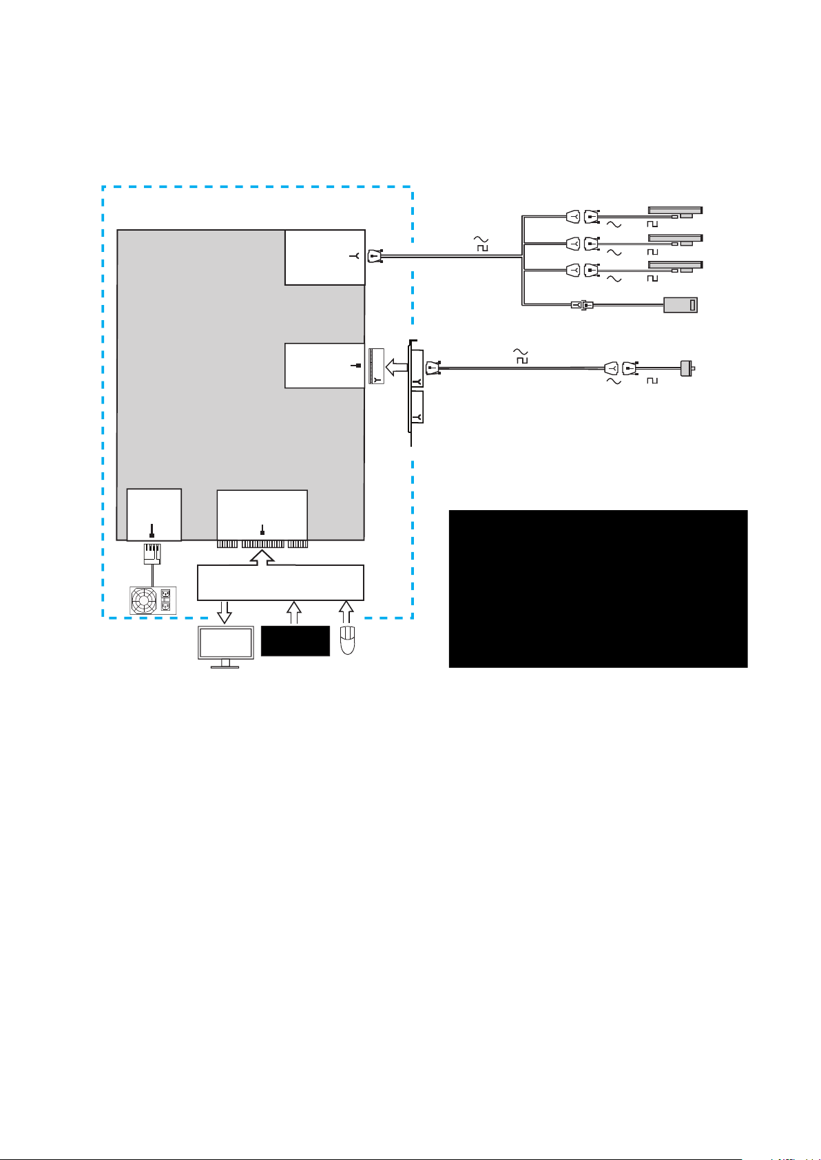
6. Connectez les câbles des plaques
de raccordement à la carte
Enfichez les câbles internes des plaques
de raccordement et le câble d'alimenta-
tion pour votre application IK 5000 dans
les connecteurs appropriés de la carte.
Pour une connexion correcte des câbles,
référez vous dans les pages précéden-
tes aux diagrammes de configuration
des connecteurs de la carte et des
plaques de raccordement.
Remarque
Enfichez les câbles dans les
connecteurs C, D et F de l'IK 5000 de
la partie supérieure de la carte avec
collerette vers le bas.
Connexion des câbles des plaques de
raccordement à la carte PC IK 5000
Plaques de raccordement
connectées aux connecteurs C, D et
F de la carte PC IK 5000
7. Fermez le boitier du PC
Vérifier que toutes les cartes,
les connexions et les plaques de
raccordement soient fixées et remettre
en place les couvercles ou panneaux.
8. Connectez les autres matériels du
système
Pour le système spécifique indiqué pré-
cédemment, référez vous aux diagram-
mes de configuration des connec-
teurs de la carte et des plaques de
raccordement. Connectez ensuite tous
les matériels du système à la carte IK
5000, aux plaques de raccordement et
aux connecteurs de la carte mère.
9. Connecter le câble d'alimentation
du PC
Vérifiez que l'interrupteur d'alimentation
du PC soit sur OFF, connectez d'abord le
câble d'alimentation au PC, puis ensuite
au secteur.
Installation de la carte PC et
des plaques de raccordement
L'installation de la carte PC IK 5000
et de ses plaques de raccordement
nécessite uniquement un tournevis et
un bracelet antistatique.
Danger de choc électrique!
Ne jamais travailler le boitier ouvert
lorsque l'appareil est sous tension
Déconnecter le câble d'alimentation
avant d'ouvrir le boitier.
Attention
Afin d'éviter la détérioration des circuits,
attacher le bracelet antistatique avant
l'installation de la carte IK 5000 dans
votre PC.
1. Déconnecter l'alimentation du PC
2. Ouvrir le boitier du PC
Enlever les couvercles ou panneaux
pour avoir accès aux slots d'extension
PCI de la carte mère.
3. Enlever les plaques de
raccordement vides
Se référer au diagramme des emplace-
ments suggérés de la carte PC et des
plaques de raccordement à la fin de ce
guide. Enlever plaques de raccordement
vides pour adapter la carte IK 5000 et
les plaques de raccordement fournis
pour votre système.
Remarque
Les emplacements de la plupart des
PCs acceptent la carte et les plaques
de raccordement. Votre PC peut avoir
besoin d'emplacement différent de
carte ou de plaques de raccordement.
4. Installation de la carte IK 5000
Insérer avec précaution la carte IK 5000
dans un slot PCI. Limitez la manipulation
de la carte autant que possible et fixez la
carte avec une vis de fixation.
5. Installer les plaques de
raccordement
Installez les plaques de raccordement
pour votre système dans les emplace-
ments appropriés et fixez les avec des
vis de fixation.
Installation et Configuration

3
Remarque
Les imperfections des signaux
n'affectent pas la précision des
mesures. Cependant, une fréquence
erronée ou des variations d'amplitude
peuvent être à l'origine d'imprécisions.
Si une sortie erronée est constatée,
ou si une erreur d'amplitude apparaît,
vérifiez le montage de l'encodeur,
l'alignement et le câblage.
• Lorsque plusieurs déplacements de
limite à limite ont été effectués sans
erreurs d'amplitude, cliquez sur le
BOUTON OK pour retourner dans
l'écran Paramétrage Encodeur.
• Cliquez sur le BOUTON PHASE DE
DISPLAY TYPE pour afficher les
courbes de Lisssajous des signaux de
sortie.
Sortie des phases encodeur
• Déplacer lentement l'encodeur entre
ses limites et évaluez le résultat de
la courbe. Un cercle indique que les
amplitudes des phases de l'encodeur
sont égales. Si la courbe n'est pas
circulaire, l'encodeur doit être réaligné
et recalibré dès le début.
• La luminosité de la courbe peut
être changée pour une meilleure
évaluation. Cliquez sur LE BOUTON
PERSISTENCE pour afficher un
champ de données. Introduire une
valeur de 1 à 1000. Une valeur
importante entraîne une courbe plus
lumineuse.
• Fermez le programme Setup
Encodeurs et centrez les axes.
7. Installation du logiciel IK 5000
Cliquez sur DÉMARRER/
PROGRAMMES/QC5000/QC5000
pour lancer le logiciel IK 5000. Il vous
est demandé le type de programme à
créer :
• Un fichier de configuration
superviseur
• Un fichier de configuration utilisateur
Répondre OUI aux deux questions.
Installation et Configuration
• Pour limiter la vitesse, introduire des
faibles valeurs pour chaque axe dans
les champs SPEED :
• Normal Speed
• Fine Speed
• Cocher la CASE ENABLE pour chaque
axe.
• Déplacez le joystick pour tous les
axes sur toute la course, cliquez sur
APPLY CAL, APPLY SETTINGS et LE
BOUTON CLOSE.
• Pour limiter la course, cliquez sur LE
BOUTON LIMIT SWITCH SETUP.
L'écran Limit Switch Setup s'affiche.
• Introduire les niveaux des fins de
course dans les champs ACTIFS pour
chaque axes (0=low, 1=high).
• Cochez la CASE ENABLE pour
chaque axe, et appuyez ensuite sur
les BOUTONS APPLY et CLOSE.
Tous les systèmes avec encodeurs
analogiques
La calibration est identique pour les
circuits en sortie de courant et de
tension. Pour calibrer un encodeur
analogique.
• Sélectionnez l'axe souhaité, confirmez
que le type correct d'axe a été
sélectionné et cliquez sur le BOUTON
WAVE DE DISPLAY TYPE.
• Cliquez sur le BOUTON CALIBRATE.
Il vous est demandé de déplacer l'axe.
• Commencez à déplacer l'axe avec
un mouvement de va et vient lent
et progressif, et appuyez sur le
BOUTON OK. La sortie du signal
sinusoïdal de l'encodeur analogique
est affichée. Après un certain temps,
la sortie de l'encodeur compte et le
nombre d'erreur compté est affiché.
Sortie des signaux d'encodeur
• Continuer de déplacer l'encodeur
lentement entre les limites jusqu'à ce
que les déplacements totaux de limite
à limite soient terminés
3. Installation du logiciel IK 5000
Insérer le CD IK 5000 dans le lecteur
de CD ROM et suivez les instructions
affichées dans l'écran pour installer le
logiciel IK 5000. Redémarrez votre PC
après l'installation.
4. Lancement de la configuration des
encodeurs IK 5000
Cliquez sur DÉMARRER/
PROGRAMMES/QC5000/ENCODER
SETUP L'écran Setup Encodeurs
utilisateur (Custom Encoder Setup) est
affiché à l'écran.
Ecran Setup Encodeurs
5. Sélectionner le type d'axe
d'encodeur
Cliquez sur le BOUTON D'UN AXE puis
sur un bouton AXIS SCALETYPE pour
sélectionner un type d'axe d'encodeur.
Continuer jusqu'à ce que tous les types
d'encodeurs soient définis.
Remarque
Aucune calibration n'est requise pour les
encodeursTTL. Passer la calibration des
encodeursTTL pour les axes utilisant
des encodeursTTL et exécuter la
phase 7.
6. Calibration des encodeurs
analogiques
• La calibration des encodeurs
analogiques doit être réalisée pour les
systèmes manuels et à CNC.
Systèmes CNC avec encodeurs
analogiques
Si votre système inclut la CNC, cliquer
sur le BOUTON JOYSTICK SETUP.
L'écran joystick Setup s'affiche.
Attention
Vous devez limiter la course avant de
calibrer les encodeurs analogiques
dans les systèmes CNC pour éviter les
dommages corporels ou à l'équipement.

4
La sélection des cases à cocher pour le système standard inclut :
Système Option Description
Tous
systèmes
NLEC Correction d'erreur non linéaire - Option
3DErrorComp Correction d'erreur volumétrique - Option
Profile Mesures comparées aux profils de dessin
- Option
Temperature Compensation de température - Option
MultipleRefFrames Plan multi-références - Option
CNC CNC Contrôle CNC - requis
Rotary Axe Q CNC - Option
Zoom Contrôle de zoom - Option avec VED
AutoFocus Autofocus Caméra - Option avec VED
XYManualZCNC CNC pour axe Z uniquement - Option
XYCNCManualZ CNC pour axes X etY uniquement - Option
SeparateJoystickSetup PID pour les axes joysticks X,Y et Z - Option
Réticules StandAloneCrosshair Système avec réticules uniquement - requis
DisplayQ Affichage des valeurs axe Q - Option
DisplayZ Affichage des valeurs axe Z - Option
Arête
optique
OE Détection d'arête par fibre optique - requis
DisplayQ Affichage des valeurs axe Q - Option
Video Edge VED Détection d'arête par vidéo - requis
Light Contrôle lumière vidéo - Option
DX9 Entrée caméra numérique - option
DisplayQ Affichage des valeurs axe Q - Option
DisplayZ Affichage des valeurs axe Z - Option
Touch Probe Full3D Mesure des valeurs X,Y et Z - requis
ContactProbes Entrée palpeur - requis
ProbeRack Contrôle de sélection de palpeur - Option
avec CNC
DisplayQ Affichage des valeurs axe Q - Option
DisplayZ Affichage des valeurs axe Z - Option
8. Validez les options de votre
système
Attention
Les paramètres de Setup définissent
l'utilisation du IK 5000 et sont protégés
par un mot de passe. Le mot de passe
du menu Setup ne doit être transmis
qu'à des personnes qualifiées.
• Cliquez sur OUTILS/OPTIONS/
ONGLET SUPERVISEUR pour
afficher le champ du mot de passe du
superviseur
Ecran des options et champ du mot
de passe du superviseur
• Introduire OPTIONS dans le champ
du mot de passe pour afficher les
options d'usine
Ecran options d'usine
• Cochez les OPTIONS D'USINE
requises pour votre système Ne pas
cocher les options qui ne concernent
pas votre système. Cocher les options
pour le système standard comme
indiqué à droite.
Les options d'usine sont requises
ou en option, et la plupart d'entre
elles peuvent être validées sans frais
additionnels. Cependant, certaines
options nécessitent une licence. Dans
ces cas, il vous sera demandé un
mot de passe d'activation avant de
redémarrer l' IK 5000.
• Si vous y êtes invités, appelez le
support client HEIDENHAIN avec
votre numéro ID système. Un mot de
passe d'activation vous sera donné.
• Cliquez sur OK pour sauvegarder la
configuration. L'application IK 5000
s'arrêtera.
• Relancez l'application IK 5000, cliquez
sur OUTILS/OPTIONS et introduire
ensuite le MOT DE PASSE du
superviseur.
Installation et Configuration
9. Initialiser zéro machine
Un zéro machine est défini par le
système à chaque mise sous tension.
Remarque
Un zéro machine peut être initialisé en
utilisant les références de l'encodeur ou
les butées fixes pour les compensations
d'erreurs SLEC, NLEC et 3D. Les
marques de référence sont requises
pour les mesures après la mise sous
tension.
Pour initialiser un zéro machine :
• Cliquez sur OUTILS/OPTIONS/
ONGLET GÉNÉRAL pour afficher
l'écran Général.
• Sélectionnez un type de zéro machine
et cliquez ensuite sur RÉGLER
MAINTENANT.
10. Configurer les encodeurs
Cliquez sur OUTILS/OPTIONS/
ENCODEURS pour afficher les
paramètres des encodeurs
11. Initialiser le type de base
Cliquez sur OUTILS/OPTIONS/MOT DE
PASSE=oem pour initialiser la base
12. Initialiser les formats des valeurs
affichées
Cliquez sur OUTILS/OPTIONS/
AFFICHAGE pour initialiser les formats
d'affichage linéaires, angulaires, de date
et d'heure.

5
13. Initialiser l'unité d'affichage écran
Cliquez sur LE CHAMP INCH/MM situé
en bas à gauche dans la barre d'état
pour initialiser inch ou mm.
CNC inclus
Les systèmes de détection optique et
vidéo et les palpeurs peuvent inclure les
commandes CNC de positionnement
des axes. Passez ces instruction si vous
possédez un système manuel
1. Configurer les fins de course
• Si votre système possède des fins de
courses pour limiter les mouvements,
cliquez sur DÉMARRER/PROGRAM-
MES/QC5000/ENCODER SETUP pour
lancer le programme de configuration
des encodeurs.
• Cliquez sur LIMIT SWITCH SETUP
BUTTON pour afficher l'écran de
configuration des fins de course.
• Introduire les paramètres des fins de
course de votre système.
2. Calibration du joystick
• Lancez le programme IK 5000, cliquez
sur OUTILS/OPTIONS CNC/ONGLET
JOYSTICK pour afficher la configura-
tion du joystick.
• Cliquez sur LE BOUTON ETA-
LONNER et suivez les instructions
affichées
• Validez les axes du joystick en co-
chant les cases ACTIVER souhaitées
3. Configurer les paramètres des axes
CNC
• Cliquez sur OUTILS/OPTIONS
CNC/ONGLET AXES X, Y, Z, ou Q
pour afficher la configuration des
paramètres CNC pour un axe.
• Pour chaque axe, régler les
paramètres pour le mouvement de
l'axe souhaité.
Attention
Le paramétrage des axes CNC est
complexe et peut être potentiellement
dangereux. Commencer le processus
de configuration avec des valeurs PRO-
PORTIONNELLEMENT très faibles pour
empêcher l'emballement du moteur et
éviter tous dommages aux équipements
ou dommages corporels. Reportez vous
au Manuel de configuration OEM
IK 5000 à www.heidenhain.fr pour des
instructions détaillées.
4. Configurer les paramètres du
joystick CNC
• Si vous choisissez de paramétrer
le joystick avant la validation des
options de votre système, cliquez
sur OUTILS/OPTIONS CNC/ONGLET
JOYSTICKX, Y, Z, ou Q pour afficher
la configuration du joystick d'un axe.
• Pour chaque axe, régler les
paramètres pour le mouvement du
joystick souhaité.
5. Configurer le positionneur digital
• Si votre système possède un
positionneur, cliquez sur OUTILS/
OPTIONS CNC/ONGLET POSIT.
DIGITAL pour afficher la configuration
du positionneur digital.
• Régler les paramètres pour la vitesse
du positionneur souhaitée et la
direction.
• Validez les axes du positionneur en
cochant les cases ACTIVER.
6. Assigner des fonctions aux
boutons
• Cliquez sur OUTILS/OPTIONS/
ONGLET BOUTONS pour afficher les
assignations aux boutons du joystick
et de la pédale de commutation
optionnelle.
• Les boutons du joystick sont
numérotés à partir de 1, de la
gauche vers la droite. Utilisez la liste
déroulante pour sélectionner les
affectations des boutons.
Remarque
Si un palpeurTP200 est inclus dans
votre système, assignez DAMP TP
200 à l'un des boutons pour prévenir
des introductions erronées pendant le
déplacement du palpeur entre les cibles.
7. Configurer les limites du logiciel
• Si vous souhaitez limiter les déplace-
ments de votre système en utilisant
les butées software, cliquez sur
OUTILS/OPTIONS CNC/ONGLET
BUTÉE SOFTWARE pour afficher les
butées de la machine et de l'utilisa-
teur. L'espace limité de l'utilisateur
est à l'intérieur de l'espace limité de la
machine.
• Introduire les valeurs limites et valider
les axes.
8. Initialiser zéro machine de l'origine
automatique
• Si cela est souhaité, un zéro machine
peut être initialisé automatiquement
lorsque l'IK 5000 est mis en service
en atteignant les marques de réfé-
rence ou les fins de course. Cliquez
sur OUTILS/OPTIONS CNC/ORIGINE
AUTOMATIQUE pour afficher les
paramètres d'origine automatique.
• Introduire les paramètres souhaités et
cocher la case ACTIVÉ.
Détection d'arête optique incluse
Suivez ces instructions si votre système
comprend la détection d'arête par fibre
optique.
1. Confirmer les niveaux acceptables
de lumière
• Cliquez sur OUTILS/OPTIONS/
PALPEURS OPTIQUES/NIVEAU
LUMIÈRE pour afficher le barre-
graphe du niveau de lumière. Les
deux barres doivent être situées entre
les valeurs extrêmes, et de couleur
verte.
• Si l'une ou l'autre barre est rouge,
régler l'extrémité de la fibre optique
pour obtenir le vert.
2. Ajouter des grossissements
• Si votre système inclut des
grossissements multiples, cliquez
sur OUTILS/OPTIONS/PALPEURS
OPTIQUES pour afficher le tableau
des grossissement.
• Cliquez sur le BOUTON NOUVEAU
pour ajouter un grossissement.
3. Calibrer les grossissements
optiques
• Si votre système inclut des
grossissements multiples, cliquez
sur PALPEURS/GROSSISSEMENTS
et sélectionnez le grossissement
maximum. Si votre système n'en
possède qu'un, sélectionnez le.
• Cliquez sur PALPEUR/MAGASIN
PALPEURS/PROPRIÉTÉS
DÉCALAGE pour afficher le BOUTON
ETALONNER.
• Cliquez sur LE BOUTON
ETALONNER et suivez les
instructions affichées pour calibrer le
grossissement.
• Continuer avec d'autres
grossissements en descendant
dans l'ordre jusqu'à ce que tous les
grossissements soient calibrés.
Détection d'arête vidéo incluse
Suivez ces instructions si votre système
comprend la détection d'arête par vidéo.
1. Configurer le zoom vidéo
• Cliquez sur OUTILS/OPTIONS/MOT
DE PASSE=oem pour afficher l'écran
de configuration OEM.
Installation et Configuration

6
Ecran configuration OEM
• Introduire un caractère dans le
champ du mot de passe, et appuyer
sur la touche Backspace de votre
clavier pour valider les boutons de
configuration.
• Cliquez sur le BOUTON ZOOM pour
afficher l'écran de configuration zoom,
initialisez les paramètres zoom de
la caméra et cliquez sur les boutons
APPLIQUER et OK.
2. Configurer la luminosité vidéo
• Cliquez sur le BOUTON LIGHT pour
afficher l'écran de configuration
du contrôle lumière, initialisez les
paramètres luminosité de la vidéo, et
cliquez sur les boutons APPLIQUER
et OK.
• Cliquez sur le bouton OK dans l'écran
de configuration OEM pour retourner
dans l'écran IK 5000.
3. Configurer la détection d'arête
vidéo
• Cliquez sur OUTILS/OPTIONS/VED
pour afficher l'écran des options VED,
• Sélectionnez le format d'image et le
type de caméra dans TABLEAU TYPE
D'IMAGE
• Initialisez d'autres paramètres VED
souhaités et cliquez sur OK.
4. Calibrer le contraste d'arête vidéo
• Cliquez sur PALPEUR/ETALONNER
ARÊTE VED et suivez les instructions
affichées
5. Lien zoom vers grossissements
• Cliquer sur PALPEUR/MAGASIN
PALPEURS/ONGLET GROSS. pour
afficher les grossissements et les
positions de zoom.
• Sélectionner les grossissements dans
le tableau du dessus et introduire les
positions de zoom souhaitées dans le
CHAMP POSITION ZOOM de l'onglet
GROSS.
6. Calibrer l'auto focus
• Si votre système possède l'auto
focus, Cliquez sur PALPEUR/
MAGASIN PALPEURS/ONGLET
AUTO FOCUS pour afficher le
BOUTON ETALONNER.
• Sélectionnez un grossissement dans
le tableau du haut, cliquez sur le
BOUTON ETALONNER et suivez les
instructions affichées à l'écran.
• Continuer jusqu'à ce que toutes
les calibrations auto focus des
grossissements soient terminées.
7. Résolution de calibration (taille
pixel)
• Cliquez sur PALPEUR/MAGASIN
PALPEURS, développer Ved et
cliquez sur CAMERA pour afficher
les grossissements. Cliquez sur
grossissement maximum.
• Cliquez sur L'ONGLET RÉSOLUTION
pour afficher le BOUTON
ETALONNER.
• Cliquez sur LE BOUTON ETALONNER
et suivez les instructions affichées
• Cochez la CASE RÉFÉRENCE pour
initialiser le grossissement maximum
comme référence. Ne pas cochez la
CASE RÉFÉRENCE des plus petits
grossissements.
• Cliquez sur L'ONGLET DÉCALAGE,
cliquez sur le BOUTON ETALONNER
et suivez les instructions affichées.
• Si votre système possède des
grossissements multiples, cliquez
sur le grossissement suivant dans
le tableau du haut et exécutez à
nouveau les étapes de la résolution et
du décalage pour ce grossissement.
• Continuez jusqu'à ce que tous les
grossissements soient terminés.
• Cliquez sur OK pour sauvegarder les
calibrations.
8. Calibration de l'alignement de la
caméra
• Cliquez sur PALPEUR/MAGASIN
PALPEURS et ensuite sur VED situé
en haut à gauche du tableau des
palpeurs.
• Cliquez sur L'ONGLET ORIENTATION
pour afficher le BOUTON
ETALONNER.
• Cliquez sur LE BOUTON
ETALONNER et suivez les
instructions affichées
Palpeur inclus
Suivez ces instructions si votre système
possède un palpeur.
1. Configurer le palpeur
• Cliquez sur OUTILS/OPTIONS/
PALPEURS pour afficher les données
de qualification et les paramètres du
type de palpeur.
• Sélectionnez un TYPE DE PALPEUR,
introduire le DIAMÈTRE DE LA
SPHÈRE DE QUALIFICATION et les
autres paramètres souhaités
2. Embout du palpeur de qualification
• Si votre palpeur est indexable, cliquez
sur PALPEUR/PALPEUR CONTACT/
SÉLECTEUR PALPEUR. L'écran de
la position du bout du palpeur est
affiché. Placez le bout du palpeur
directement vers le bas. Sautez à la
prochaine étape si votre palpeur n'est
pas indexable.
Le bout du palpeur indexable est
positionné vers le bas
• Cliquez sur PALPEUR/MAGASIN
PALPEURS pour afficher les palpeurs
de votre système
• Cliquez sur PALPEURS dans le
tableau en haut à gauche, et cliquez
sur PALPEURS À CONTACT dans le
tableau en haut à droite de l'écran de
la librairie des palpeurs.
• Cliquez sur LE BOUTON
ETALONNER et suivez les
instructions affichées
3. Etalonner le palpeur
Si votre système inclut un palpeur et
une détection vidéo d'arête, le palpeur
doit être calibré pour afficher les
positions qui doivent être identiques
à celles du détecteur vidéo. Si votre
système n'inclut pas la détection vidéo
des arêtes, passez cette étape.
• Cliquez sur PALPEUR/MAGASIN
PALPEURS pour afficher les palpeurs
de votre système
• Cliquez sur PALPEURS CONTACT
dans le tableau en haut à droite de
l'écran de la librairie des palpeurs,
cochez la CASE RÉFÉRENCE et
cliquez ensuite sur le BOUTON
ETALONNER. Suivez les instructions
affichées.
Tous systèmes
1. Correction d'erreur
Si cela est souhaité, des corrections
d'erreurs telles que SLEC, NLEC, et des
corrections comp 3D et d'équerrage
peuvent être appliquées. Reportez vous
au Manuel de configuration OEM
IK 5000 à www.heidenhain.de pour
des instructions détaillées.
2. Espace de travail
Le positionnement des fenêtres
du bureau de l'IK 5000 peut être
sauvegardé comme espace de travail
par défaut ou rappelé ultérieurement.
Cliquez sur VUE/ESPACE DE TRAVAIL/
SAUVEGARDER ESPACE DE TRAVAIL
pour sauvegarder l'écran de l'IK 5000
comme espace de travail.
Installation et Configuration

IK 5293
X, Y, Z
Axis encoders
and foot switch
44 pin edge
+5V, +12V
Ground
4 pin header
E
A
681041-02
(Foot switch)
G
PC Motherboard
Connections
IK 5293 Card
9 pin
PCI Bus
Slot connector
MTouch probe
Touch probe
50 pin header
D
50 pin
IK 5293
Metrology Computer
( 1 Vpp)
( TTL)
540550-40
540550-10
on request
IK 5293 Card
1 Vpp/ TTL
1 Vpp/ TTL
1 Vpp/ TTL
Card, flyout and connector configurations

IK 5394-EG
X, Y, Z
Axis encoders
and foot switch
44 pin edge
Q Axis
Encoder
30 pin header
+5V, +12V
Ground
4 pin header
E
A
C
H
44 pin
30 pin
G
PC Motherboard
Connections
IK 5394-EG Card
26 pin
PCI Bus
Slot connector
Optical light
inputs
2 optical jacks
TLight source
Screen sensor
P
R
681041-02
(Foot switch)
540541-24
540541-05
681049-xx
681049-xx
J
IK 5394-EG
Metrology Computer
IK 5394-EG Card
Comparator
( 1 Vpp)
( TTL)
( 1 Vpp)
( TTL)
540550-40
540550-10
1 Vpp/ TTL
1 Vpp/ TTL
1 Vpp/ TTL
1 Vpp/ TTL
Card, flyout and connector configurations

IK 5394-3D
X, Y, Z
Axis encoders
and foot switch
44 pin edge
Q Axis
Encoder
30 pin header
A
C
681041-02
(Foot switch)
H
44 pin
30 pin
IK 5394-3D Card
25 pin 44 pin
Video light control
50 pin header
D
50 pin
1
2
8
Light
Controller
N
Video camera
zoom control
30 pin header
F
30 pin
Video lamps
Zoom motor
IK 5394-3D
Metrology Computer
+5V, +12V
Ground
4 pin header
EG
PC Motherboard
Connections
PCI Bus
Slot connector
Video
Camera
IK 5394-3D Card
K
540541-24
540541-05
on request
on request
( 1 Vpp)
( TTL)
( 1 Vpp)
( TTL)
540550-40
540550-10
9 pin
MTouch probe
on request
1 Vpp/ TTL
1 Vpp/ TTL
1 Vpp/ TTL
1 Vpp/ TTL
Card, flyout and connector configurations

IK 5493
X, Y
Axis encoders
and foot switch
44 pin edge
Q Axis
Encoder
and CNC
30 pin header
+5V, +12V
Ground
4 pin header
E
A
C
681041-02
(Foot switch)
H
44 pin
30 pin
G
IK 5493 Card
26 pin
Q Axis
CNC
26 pin
Joystick
15 pin
15 pin
Axis
limit
switch
Q
Motor
RS-232C
Stepper
amps
only
X,Y Axis
CNC
26 pin
Joystick
15 pin
15 pin
Axis
limit
switches
X
Motor
Y
Motor
RS-232C
Stepper
amps
only
X, Y Axis
CNC control
26 pin edge
B
PCI Bus
Slot connector
J
Optical light
inputs
2 optical jacks
T
P
R
IK 5493
Metrology Computer
IK 5493 Card
Light source
Screen sensor
Comparator
Servo/Stepper
Servo/Stepper
PC Motherboard
Connections
W
RS-232C
9 pin
540540-24
540540-05
540660-56
540660-53
(Stepper)
(Servo)
681045-01
681046-01
(Stepper)
(Servo)
681045-01
681046-01
540660-56
540660-53
540660-05
540541-24
540541-05
681049-xx
681049-xx
( 1 Vpp)
( TTL)
( 1 Vpp)
( TTL)
1 Vpp/ TTL
1 Vpp/ TTL
1 Vpp/ TTL
681044-xx
681044-xx
Card, flyout and connector configurations

IK 5494-2D
X, Y, Z
Axis encoders
and foot switch
44 pin edge
Q Axis
Encoder
and CNC
30 pin header
+5V, +12V
Ground
4 pin header
E
A
C
681041-02
(Foot switch)
H
44 pin
30 pin
G
IK 5494-2D Card
26 pin
Q Axis
CNC
26 pin
Joystick
15 pin
15 pin
Axis
limit
switch
Q
Motor
RS-232C
Stepper
amps
only
Servo/Stepper
XYZ Axis
CNC
26 pin
Joystick
15 pin
15 pin
Axis
limit
switches
X
Motor
Y
Motor
Z
Motor
RS-232C
Stepper
amps
only
X, Y, Z Axis
CNC control
26 pin edge
B
PCI Bus
Slot connector
J
Video light control
50 pin header
D
IK 5494-2D Card
IK 5494-2D
Metrology Computer
Video
Camera
Servo/Stepper
Video camera
zoom control
30 pin header
F
25 pin 44 pin
50 pin
1
2
8
Light
Controller
N
30 pin
Video lamps
Zoom motor
K
PC Motherboard
Connections
W
RS-232C
9 pin
540660-56
540660-53
(Stepper)
(Servo)
681045-01
681046-01
(Stepper)
(Servo)
681045-02
681046-02
540660-56
on request
on request
540660-53
540660-05
540550-40
540550-10
540541-24
540541-05
( 1 Vpp)
( TTL)
( 1 Vpp)
( TTL)
1 Vpp/ TTL
1 Vpp/ TTL
1 Vpp/ TTL
1 Vpp/ TTL
681044-xx
681044-xx
Card, flyout and connector configurations

IK 5494-3D
X, Y, Z
Axis encoders
and foot switch
44 pin edge
Q Axis
Encoder
and CNC
30 pin header
A
C
681041-02
(Foot switch)
H
44 pin
30 pin
IK 5494-3D Card
26 pin
44 pin
9 pin
Q Axis
CNC
26 pin
Joystick
15 pin
15 pin
Axis
limit
switch
Q
Motor
RS-232C
Stepper
amps
only
XYZ Axis
CNC
26 pin
Joystick
15 pin
15 pin
Axis
limit
switches
X
Motor
Y
Motor
Z
Motor
RS-232C
Stepper
amps
only
X, Y, Z Axis
CNC control
26 pin edge
B
J
K
M
Video light control
and touch probe
50 pin header
D
50 pin
1
2
8
Light
Controller
Video lamps
Touch probe
+5V, +12V
Ground
4 pin header
EG
PCI Bus
Slot connector
IK 5494-3D Card
IK 5494-3D
Metrology Computer
Video
Camera
Servo/Stepper
Video camera
zoom control
30 pin header
F
Servo/Stepper
PC Motherboard
Connections
W
RS-232C
9 pin
25 pin
N
30 pin
Zoom motor
on request
on request
on request
540660-56
540660-53
(Stepper)
(Servo)
681045-02
681046-02
540660-56
540660-53
540660-05
540550-40
540550-10
540541-24
540541-05
( 1 Vpp)
( TTL)
( 1 Vpp)
( TTL)
1 Vpp/ TTL
1 Vpp/ TTL
1 Vpp/ TTL
1 Vpp/ TTL
681044-xx
681044-xx
Card, flyout and connector configurations
Other manuals for IK 5000 QUADRA-CHEK
3
Table of contents
Languages:
Other HEIDENHAIN Computer Hardware manuals
Popular Computer Hardware manuals by other brands

Motorola
Motorola M68HC08 Reference manual

ST
ST X-NUCLEO-OUT07A1 user manual

EK-Quantum
EK-Quantum Velocity D-RGB - AMD Ryzen Edition user guide

Vega
Vega ARIES v3.0 Product reference manual

North Star
North Star HRAM-64 User's & technical manual

Siemens
Siemens SENTRON PROFIBUS DPV1 Series operating instructions