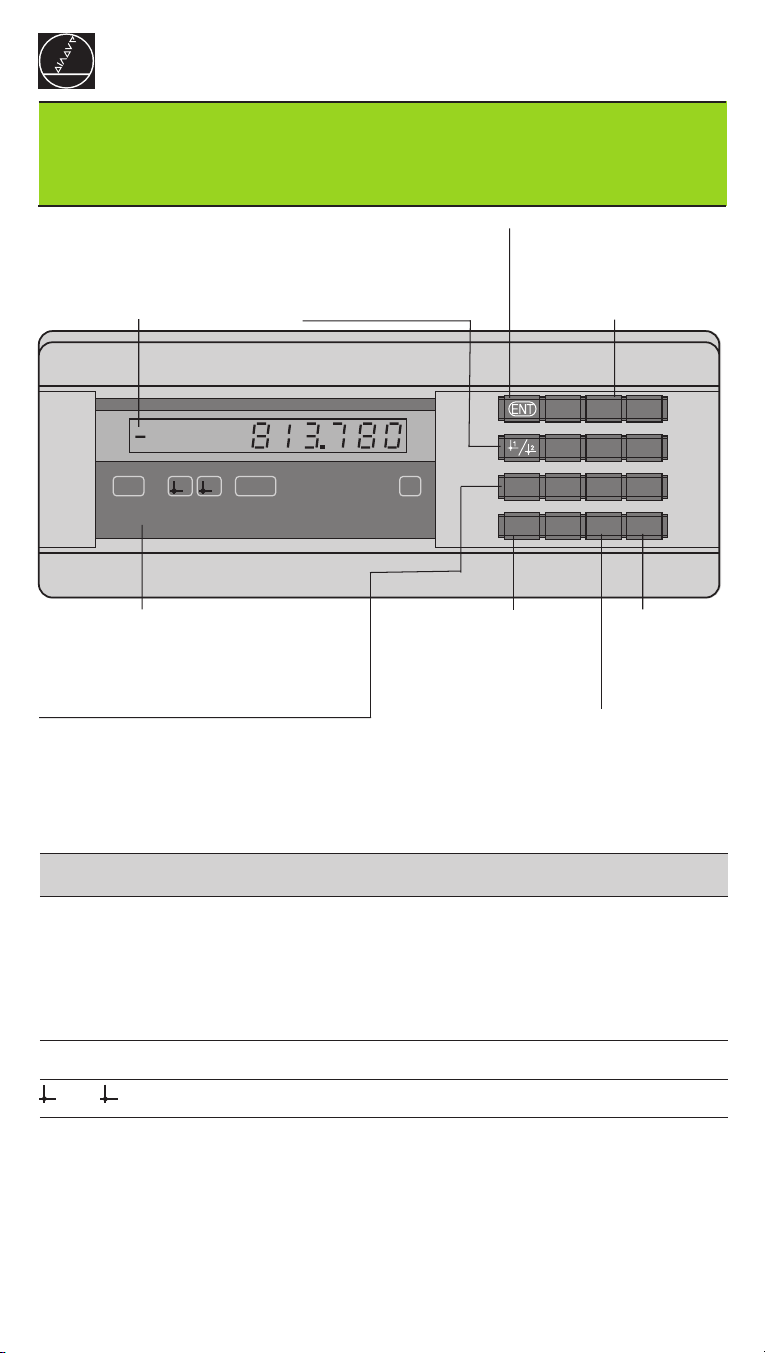
Operating Parameters
The parameters are divided into “user parameters“and “protected operating param-
eters," which can only be accessed by entering a code number.
User parameters
User parameters are operating parameters that you can change without entering the
code number: They are designated P00 to P30, P50, P51, P79, P86
Calling user parameters
To call user parameters immediately after switch-on:
➤➤
➤➤
➤Press the MOD key as long as is visible in the display.
To call user parameters during operation:
➤➤
➤➤
➤Press and hold the CL key, then press MOD.
To go directly to a specific user parameter:
➤➤
➤➤
➤Press and hold the CL key, then press the first digit of the parameter number.
➤➤
➤➤
➤Release both keys and press the second digit.
Protected operating parameters
Before you can change protected operating parameters you must enter the code
number 95 148 through : They remain accessible until you switch off
the position display.
To page through the parameter list
➤➤
➤➤
➤Forward paging: Press the MOD key.
➤➤
➤➤
➤Backward paging: Press the 1 / 2 key.
By paging on, you automatically enter any change you've made in a parameter.
To change operating parameters
➤➤
➤➤
➤Increase the parameter value with the decimal point key, or
➤➤
➤➤
➤Decrease the parameter value with the minus key, or
➤➤
➤➤
➤Enter the numerical value for the operating parameter, e.g. for P41 ( SET blinks).
To correct your entries and show the parameter designation
➤➤
➤➤
➤Press the CL key.
To exit the operating parameters
➤➤
➤➤
➤Press ENT. All changes made become effective.
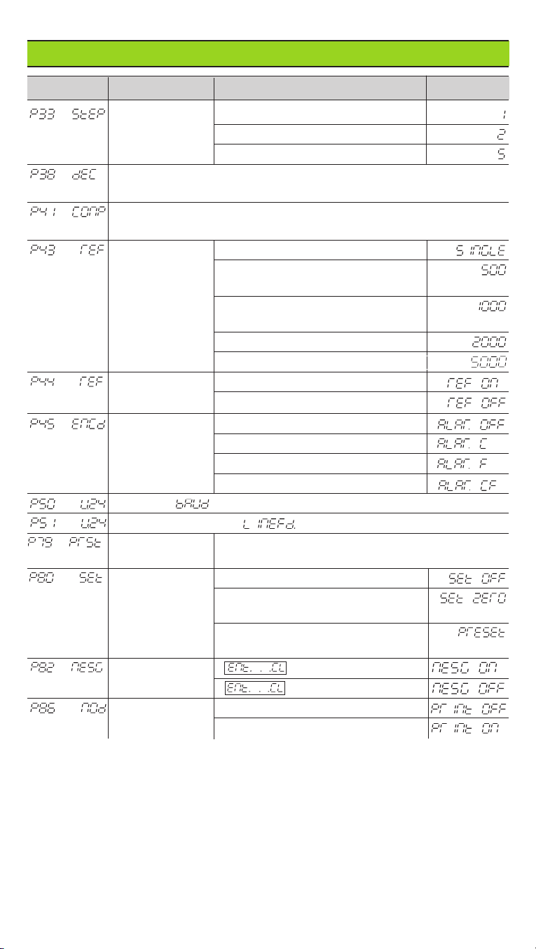
Operating Parameter List
Parameter Meaning Function / Effect Setting
Enter code number 95 148 to change a protected operating
parameter.
Unit of measure Display in millimeters
Display in inches
Counting Normal (
Positive
)
Direction
direction Inverse (
Negative
)
Subdivision of encoder signal period 400, 320, 256, 200, 160,
Subdivision
128, 100, 80, 50, 40, 20, 10, 8, 5, 4, 2, 1, 0.8, 0.5, 0.4, 0.2, 0.1