Contents
Page
Contents
Page
Technical 1
Description
1.1
1.1.1
1.1.2
1.2
1
2.1
1.2.2
1.2.3
12.4
1.3
1.3.1
External
Functions T30
Pin
Layout
X41
(00)
(25-pole D-Submlniature Socket) T30
External Zero
Reset
T30
Storage
(Pulse.
Contact)
T31
Zero Crossover Signal
T31
EMERGENCY
STOP
Signal
T31
Linear and Angle Encoders
132
Layout of Encoder
Flange
Sockets
Xl
X4
T32
Connection of
Probe
Systems T33
Pin
Layout
Xl
0(15·pole O-Subminiature Socket) _
135
Specifications
136
Dimensions T38
4
4.1
4.2
4.3
4.4
4.5
5
5.1
6
6.1
7
8
______________
G1
1.3.2
1.3.3
1 4
1.4 1
1.4.2
2
2.1
22
2.3
2.4
2.5
3
31
3,1.1
312
3.1.3
3.2
3.3
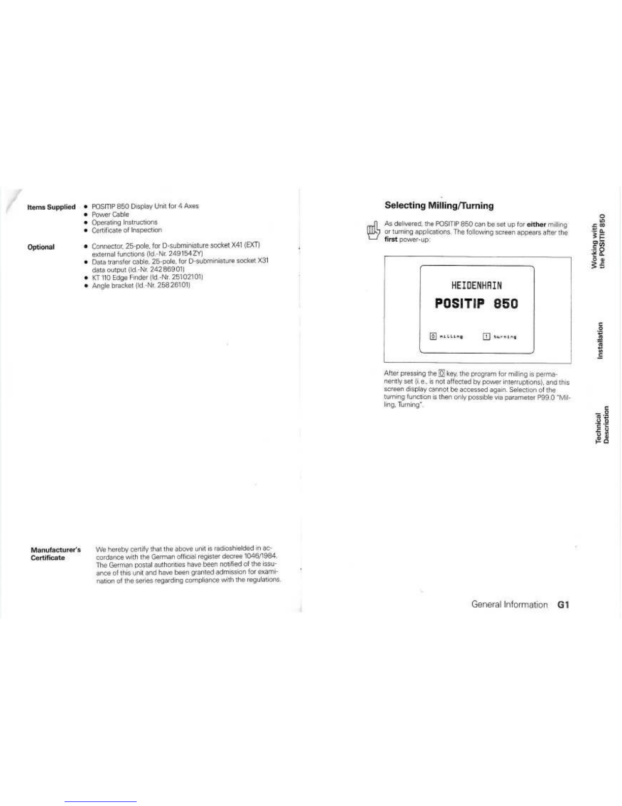
General
Information
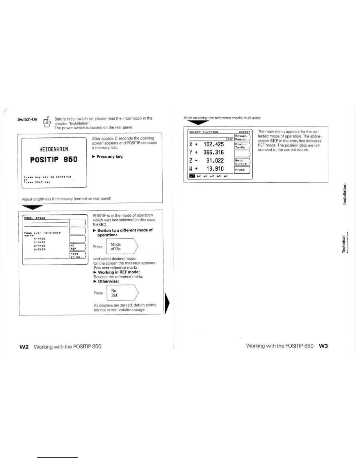
Working
with
the
POSITIP
850
For
Milling
W1
Installation 1Connections and Controls
(Rear
of Umt)
11
2Mounting the
POSITIP
850
12
3Connecting
Une8r
and
Angle
eョ」ッ、B・セGセウ]]]]ZGR
4Connecting
the
KT
110
Edge Finder
セ
13
5Power
cッョョ・」エゥッョセZセセセZ]]]]]]]iS
6
SWItch-On
and Function Check
]3
7Optlmizing the Parameters
14
Parameters
T1
User Parameters
T1
Olanging User Parameters
T2
Overview of User Parameters
T4
Operating Parameters
T5
AcceSSing
the Operating Parameters T5
Configunng the User Parameters T7
Presenrng the User Parameters
T9
Overview
of
Operating
Parameters
T10
Tables
T14
Display Step, Stgnal Period and Subdivision
Factor
for
linear Encoders
-c-::-:-:c-:c---::---
T14
Display
Step.
lme
Count and Subdivision Factor
lor
Angle
eョ」ッ、・セウセセセセセセセセセセセセtQT
Distance-Coded Reference Marks T15
Parameter Description T16
User Parameters T16
Operating Parameters P
T17
RS·232-C/V.24
Data
Interface
T21
DefinItion of the RS-232-C/V.24 Interface
T21
Pin
LaYOut/Signal
Description
T21
Connection of External
UnIlS
(Wiring) T22
Data
Transfer
Rate
(Baud
Rate)
T23
Data
Format T23
Data
Transfer T24
Measured Value Output T25
Storage
Via
RS
232-C Interface T25
Storage
Via
External
Functions T26
Sequence of Character Output T27
External Input/Output of Programs T29
Input/Output of Operating Parameters T29
G2
General
Information
General
Information
G3