Hilti DD 160 User manual

DD 160
Operating instructions en
Mode d’emploi fr
Manual de instrucciones es
Manual de instruções pt
Printed: 08.07.2013 | Doc-Nr: PUB / 5069572 / 000 / 03

1
Ꙥ
ꙥ
ꙦꙴꚀ
ꙣ
꙳
ꙭ
Ꙫ
ꙩ
Ꙩ
ꙧ
ꙫ
Ꙭ
꙯
꙲
ꙮ
꙯
꙰
꙱
This Product is Certified
Ce produit est certifié
Este producto esta certificado
Este produto está certificado
C US
Printed: 08.07.2013 | Doc-Nr: PUB / 5069572 / 000 / 03

2
ꙴ
ꙵ
Ꚁ
ꚁ
꙾
꙼
ꙷ ꙸꙶ
ꙹ ꙿꙺ ꙽ ꚃ
ꚃ
Ꚃ
ꙸ
ꙷ
꙼
ꙶ ꙹ
꙾
ꙻ
Printed: 08.07.2013 | Doc-Nr: PUB / 5069572 / 000 / 03

ꚋꚌ
Ꚇ
ꚉ
ꚅ
Ꚅ
Ꚋ
ꚍ
ꚇ
Ꚉ
3
4
PPô
5
Printed: 08.07.2013 | Doc-Nr: PUB / 5069572 / 000 / 03

PPô
6
7
8
PD[
9
10
11
12
Printed: 08.07.2013 | Doc-Nr: PUB / 5069572 / 000 / 03

13
14
16
15
Printed: 08.07.2013 | Doc-Nr: PUB / 5069572 / 000 / 03

ORIGINAL OPERATING INSTRUCTIONS
DD 160 diamond coring system
It is essential that the operating instructions
are read before the machine is operated for
the first time.
Always keep these operating instructions to-
gether with the machine.
Ensure that the operating instructions are
with the machine when it is given to other
persons.
Contents Page
1 General information 2
2Description 4
3 Accessories 6
4 Technical data 6
5 Safety instructions 7
6Beforeuse 9
7 Operation 12
8 Care and maintenance 15
9 Troubleshooting 16
10 Disposal 18
11 Manufacturer’s warranty 18
1These numbers refer to the corresponding illustra-
tions. The illustrations can be found on the fold-out cover
pages. Keep these pages open while studying the oper-
ating instructions.
In these operating instructions, the designation “the ma-
chine” always refers to the DD 160 diamond core drilling
machine.
Operating controls, parts and indicators (motor unit
and drill stand) 1
DD 160 diamond core drilling machine
@On / off switch
;Theft protection indicator
=Service indicator
%Drilling performance indicator
&Gear selector
(Gearing section
)Motor
+Carbon brush cover
§Water swivel
/Chuck
:Supply cord with GFCI
·Carriage lock
$Carriage play adjustment screws
£Carriage
|Hand wheel shaft
¡Supply cord holder
QDrill stand
WEnd stop screw
ÆEnd stop screw
Drill stand with combination base plate 2
WEnd stop screw
ERail
RVacuum release valve
TPressure gauge
ZLeveling indicator
UVacuum hose connector
ICombination base plate
OGrip
PAdjusting lever
ÜHole center indicator
[Leveling screw
]Vacuum seal
Drill stand with anchor base plate 2
ÆEnd stop screw
ºRail
•Anchor base plate, small
ALeveling screw
Various accessories 3
SStar handle
DLever
FDepth gauge
GJack screw
HRota-Rail (column swivel)
JWheel assembly
ÄVacuum base plate
Water collection system 3
KHolder
LWater collector
ÖSeal
en
1
Printed: 08.07.2013 | Doc-Nr: PUB / 5069572 / 000 / 03

VACUUM
VACUUM
1 General information
1.1 Safety notices and their meaning
DANGER
Draws attention to imminent danger that will lead to
seriousbodilyinjuryorfatality.
WARNING
Draws attention to a potentially dangerous situation that
could lead to serious personal injury or fatality.
CAUTION
Draws attention to a potentially dangerous situation that
could lead to slight personal injury or damage to the
equipment or other property.
NOTE
Draws attention to an instruction or other useful informa-
tion.
1.2 Explanation of the pictograms and other
information
Prohibition signs
Transport by
crane is not
permissible.
Warning signs
General
warning
Warning:
electricity
Warning: hot
surface
Obligation signs
Wear eye
protection.
Wear a hard
hat.
Wear ear
protection.
Wear
protective
gloves.
Wear safety
shoes.
Symbols
Read the
operating
instructions
before use.
Lock symbol Equipped
with theft
protection
system
Service
indicator
Return waste
material for
recycling.
Amps Volts Alternating
current
Hertz Nominal
speed under
no load
Diameter Millimeters
Revolutions
per minute
Revolutions
per minute
Drilling
performance
indicator
On the drill stand and the vacuum base plate
Upper: An additional means of securing the drill stand
must be employed when the machine is used for hori-
zontal drilling with the vacuum securing method.
en
2
Printed: 08.07.2013 | Doc-Nr: PUB / 5069572 / 000 / 03

PRCD
GFCI
208188 B/2.2004
Lower: Use of the vacuum securing method for overhead
drilling with the drill stand is not permissible.
On the machine
Use of the water collection system in conjunction with
a wet-type industrial vacuum cleaner is a mandatory
requirement for working on ceilings.
On the machine
Operate the equipment only with a properly functioning
GFCI.
Location of identification data on the machine
The type designation and serial number can be found on
thetypeidentificationplateonthemachine.Makeanote
of this data in your operating instructions and always refer
to it when making an enquiry to your Hilti representative
or service department.
Type:
Generation: 02
Serial no.:
en
3
Printed: 08.07.2013 | Doc-Nr: PUB / 5069572 / 000 / 03

2 Description
2.1 Use of the product as directed
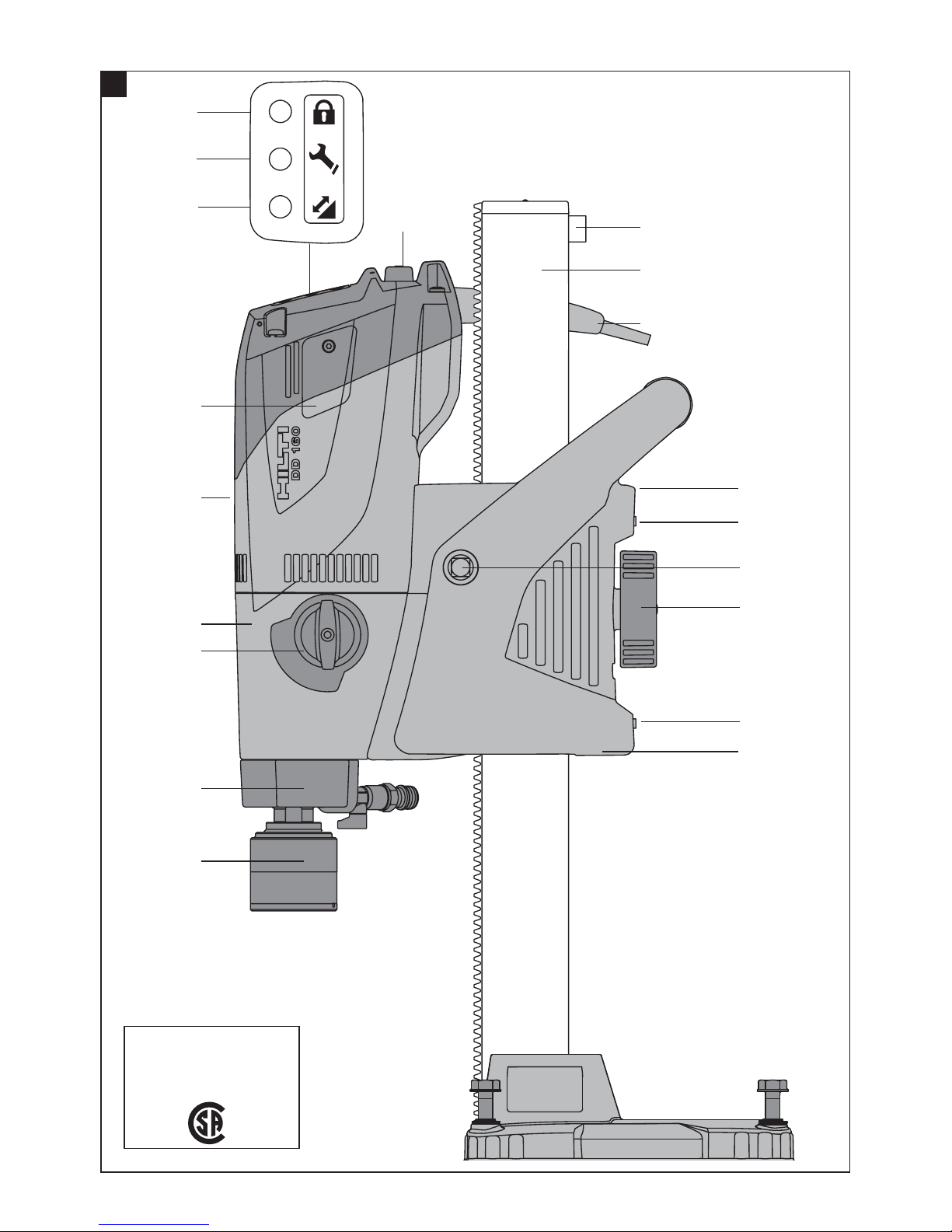
The DD 160 is an electrically-powered, rig-type diamond core drilling machine for drilling through-holes and blind
holes in (reinforced) mineral materials using diamond core bits and the wet drilling technique (hand-held use is not
permissible).
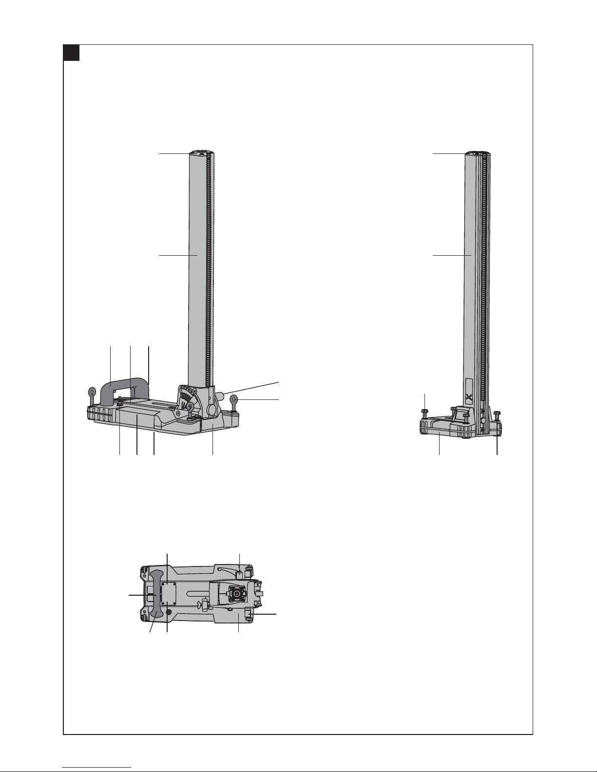
The machine must be adequately secured to the working surface with an anchor or vacuum base plate before use.
To avoid injury, use only genuine Hilti core bits and DD 160 accessories.
Observe the safety rules and operating instructions for the accessories used.
Observe the information printed in the operating instructions concerning operation, care and maintenance.
Nationally applicable industrial safety regulations must be observed.
The machine, accessories and cutting tools may present hazards when handled incorrectly by untrained personnel or
when used not as directed.
Use of the water collection system in conjunction with a wet-type industrial vacuum cleaner is a mandatory requirement
for working overhead.
An additional means of securing the drill stand must be employed when the machine is secured with the vacuum base
plate (accessory) for horizontal drilling.
Do not strike the base plate with a hammer or other heavy object when making adjustments to it.
Tampering with or modification of the machine, drill stand and accessoriesisstrictlyprohibited.
WARNING
The machine may be operated only when connected to an adequately-rated electric supply equipped with an
earth (ground) conductor.
WARNING
Drilling into materials hazardous to the health (e.g. asbestos) is not permissible.
DANGER
Use only the genuine Hilti accessories or ancillary equipment listed in the operating instructions. Use of
accessories or ancillary equipment not listed in the operating instructions may present a risk of personal injury.
2.2 Use of the machine with various items of equipment
Equipment Core bit diameters Drilling direction
Without water collection system and wet-type
industrial vacuum cleaner
25…202 mm (1" to 8") Not upwards
With water collection system 25…162 mm (1" to 6¼") Not upwards
With water collection system and wet-type in-
dustrial vacuum cleaner
25…162 mm (1" to 6¼") All directions
2.3 Gears and corresponding core bit diameters
Gear Core bit diameters
(mm)
Core bit diameters
(inches) No-load speed /min
1 152…202 6…8 420
2 72…142 2³⁄₄…5¹⁄₂ 700
3 25…67 1…2¹⁄₂ 1,570
en
4
Printed: 08.07.2013 | Doc-Nr: PUB / 5069572 / 000 / 03

2.4 Status indicator
LED indicators State Description / information
Theft protection indicator (2) Blinking yellow light The machine’s theft protection system
is active and must be unlocked with the
TPS key.
Service indicator (3) Red light and the machine
starts
The carbon brushes are badly worn.
After the lamp lights for the first time,
the machine may continue to be used
for several hours before the automatic
cut-out is activated. Have the carbon
brushes changed in good time so that
the machine is always ready for use.
Red light and the machine
doesn’t start
The carbon brushes must be changed.
Blinking red light Temporary fault, see Troubleshooting
section.
Drilling performance display (4) Orange light Contact pressure too low
Green light Optimum contact pressure
Red light Contact pressure too high
2.5 TPS theft protection system (optional)
The machine may be optionally equipped with the TPS theft protection system. If equipped with this feature, the
machine can be unlocked and made ready for operation only through use of the corresponding TPS key.
2.6 Items supplied as standard
1 Machine with hand wheel or lever
1 Operating instructions
1 Cardboard box
2.7 Using extension cords
Use only extension cords of a type approved for the application and with conductors of adequate gauge.
Recommended minimum conductor gauge (cross section) and max. cable lengths
Conductor cross section AWG12 AWG10
Mains voltage 120 V 75 ft 125 ft
Mains voltage 127 V 75 ft 125 ft
Do not use extension cords with 14 AWG or 16 AWG conductors. Use only extension cords equipped with an earth
conductor.
2.8 Using a generator or transformer
This machine may be powered by a generator or transformer when the following conditions are fulfilled: The unit must
provideapoweroutputinwattsofatleasttwicethevalueprintedonthetype identification plate on the machine. The
operating voltage must remain within +5% and -15% of the rated voltage at all times, frequency must be in the 50 – 60
Hz range and never above 65 Hz, and the unit must be equipped with automatic voltage regulation and starting boost.
NOTE
Switching other machines or appliances on and off can cause undervoltage and/or overvoltage peaks which could
damage the machine. Never operate other machines from the generator/transformer at the same time.
en
5
Printed: 08.07.2013 | Doc-Nr: PUB / 5069572 / 000 / 03

3 Accessories
Designation Short designation Description
TPS theft protection system with
company card, company remote
and TPS‑K key
Option
Water collection system
Hand wheel (lever)
Hand wheel (star handle)
Core bit extension (BI+)
Drill stand (with anchor base plate)
Drill stand (with combination base
plate and tilt mechanism)
Vacuum base plate DD-ST-120/160-VBP
Depth gauge
Jack screw
Rota-Rail (column swivel)
4 Technical data
Right of technical changes reserved.
NOTE
The machine is available in various voltage ratings. Please refer to the machine’s type identification plate for details of
its rated voltage and rated input power.
Rated voltage [V] 120 127
Rated current [A] 19.5 18.5
Mains frequency [Hz] 60 50/60
Other information about the machine
Rated speed under no load 420 /min (1st gear), 700 /min (2nd gear), 1570 /min (3rd
gear)
Max. permissible water supply pressure 5 bar (72.52 psi)
Dimensions of the system with anchor base plate, (L x
WxH)
400 mm (15.75") x 165 mm (6.5") x 945 mm (37.2")
Dimensions of the system with combination base plate,
(LxWxH)
610 mm (24.02") x 250 mm (9.84") x 952 mm (37.48")
Weight of the system with anchor base plate 16.3 kg (35.93 lb)
Weight of the system with combination base plate 19.3 kg (42.55 lb)
Protection class Protection class I (earthed)
en
6
Printed: 08.07.2013 | Doc-Nr: PUB / 5069572 / 000 / 03

5 Safety instructions
5.1 General safety rules
a) Warning! Read and understand all instructions.
Failure to follow all instructions listed below may
result in electric shock, fire and/or serious personal
injury. SAVE THESE INSTRUCTIONS.
5.1.1 Work area
a) Keep your work area clean and well lit. Cluttered
benches and dark areas invite accidents.
b) Do not operate power tools in explosive atmo-
spheres, such as in the presence of flammable
liquids, gases or dust. Power tools create sparks
which may ignite the dust or fumes.
c) Keep bystanders, children and visitors away while
operating a power tool. Distractions can cause you
to lose control.
5.1.2 Electrical safety
a) Grounded tools must be plugged into an outlet
properly installed and grounded in accordance
with all codes and ordinances. Never remove the
grounding prong or modify the plug in any way. Do
not use any adapter plugs. Check with a qualified
electrician if you are in doubt as to whether the
outlet is properly grounded. If the tools should
electrically malfunction or break down, grounding
provides a low resistance path to carry electricity
away from the user.
b) Avoid body contact with grounded surfaces such
as pipes, radiators, ranges and refrigerators.
There is an increased risk of electric shock if your
body is grounded.
c) Don’t expose power tools to rain or wet condi-
tions. Water entering a power tool will increase the
risk of electric shock.
d) Do not abuse the cord. Never use the cord to carry
the tools or pull the plug from an outlet. Keep cord
away from heat, oil, sharp edges or moving parts.
Replace damaged cords immediately. Damaged
cords increase the risk of electric shock.
e) When operating a power tool outside, use an
outdoor extension cord marked “W-A” or “W”.
These cords are rated for outdoor use and reduce
theriskofelectricshock.
5.1.3 Personal safety
a) Stay alert, watch what you are doing and use
common sense when operating a power tool. Do
not use tool while tired or under the influence of
drugs, alcohol or medication. A moment of inatten-
tion while operating power tools may result in serious
personal injury.
b) Dress properly. Do not wear loose clothing or
jewelry. Contain long hair. Keep your hair, clothing
and gloves away from moving parts. Loose clothes,
jewelry or long hair can be caught in moving parts.
c) Avoid accidental starting. Be sure switch is off
before plugging in. Carrying tools with your finger
on the switch or plugging in tools that have the switch
on invites accidents.
d) Remove adjusting keys or switches before turning
the tool on. A wrench or a key that is left attached
to a rotating part of the tool may result in personal
injury.
e) Do not overreach. Keep proper footing and bal-
ance at all times. Proper footing and balance en-
ables better control of the tool in unexpected situa-
tions.
f) Use safety equipment. Always wear eye protec-
tion.Dust mask, non-skid safety shoes, hard hat or
hearing protection must be used for appropriate con-
ditions.
5.1.4 Tool use and care
a) Use clamps or other practical way to secure and
support the workpiece to a stable platform. Hold-
ing the work by hand or against your body is unstable
and may lead to loss of control.
b) Do not force tool. Use the correct tool for your
application. The correct tool will do the job better
and safer at the rate for which it is designed.
c) Do not use tool if switch does not turn it on or off.
Any tool that cannot be controlled with the switch is
dangerous and must be repaired.
d) Disconnect the plug from the power source before
making any adjustments, changing accessories,
or storing the tool. Such preventive safety measures
reduce the risk of starting the tool accidentally.
e) Store idle tools out of reach of children and
other untrained persons. Tools are dangerous in
the hands of untrained users.
f) Maintain tools with care. Keep cutting tools sharp
and clean. Properly maintained tools with sharp cut-
ting edges are less likely to bind and are easier to
control.
g) Check for misalignment or binding of moving
parts, breakage of parts and any other condition
that may affect the tool’s operation. If damaged,
have the tool serviced before using. Many acci-
dents are caused by poorly maintained tools.
h) Use only accessories that are recommended by
the manufacturer for your model. Accessories that
may be suitable for one tool may become hazardous
when used on another tool.
5.1.5 Service
a) Tool service must be performed only by qualified
repair personnel. Service or maintenance performed
by unqualified personnel could result in a risk of injury.
b) When servicing a tool, use only identical replace-
ment parts. Follow instructions in the Mainte-
nance section of this manual. Use of unauthorized
parts or failure to follow Maintenance Instructions
may create a risk of electric shock or injury.
en
7
Printed: 08.07.2013 | Doc-Nr: PUB / 5069572 / 000 / 03

5.2 Proper organization of the work area
a) Approval must be obtained from the site engineer
or architect prior to beginning drilling work. Drilling
work on buildings and other structures may influence
the statics of the structure, especially when steel
reinforcing bars or load-bearing components are cut
through.
b) When drilling through walls, cover the area behind
the wall, as material or the core may fall out on
the other side of the wall. When drilling through
ceilings, secure (cover) the area below as drilled
material or the core may drop out and fall down.
c) Place the mounting device on a solid, flat and level
surface. If the mounting device can slip or wobble,
the machine cannot be guided smoothly and safely.
d) Check the nature of the surface. Rough surfaces
may reduce holding power. Coatings or composite
materials may pull away from the surface while you
are working.
e) Do not overload the mounting device and do not
use it as a substitute for a ladder or platform.
Overloading the mounting device or standing on it
may shift its center of gravity to a higher position,
causingittotipover.
f) Wear respiratory protection if the work causes
dust.
g) It is recommended that rubber gloves and non-
skid shoes are worn when working outdoors.
h) Keep the supply cord, extension cord, suction
hose and vacuum hose away from rotating parts.
i) Donotworkfromaladder.
5.2.1 General safety rules
a) Keep the grips dry, clean and free from oil and
grease.
b) Never leave the machine unattended.
c) Children must be instructed not to play with the
machine.
d) The machine is not intended for use by children,
by debilitated persons or those who have received
no instruction or training.
e) Never operate the machine without the supplied
GFCI ground fault circuit interrupter (machines
without GFCI: Never operate the machine without
an isolating transformer). Test the GFCI each time
before use.
f) Check the machine and its accessories for any
damage. Guards, safety devices and any slightly
damaged parts must be checked carefully to en-
sure that they function faultlessly and as intended.
Check that moving parts function correctly with-
out sticking and that no parts are damaged. All
parts must be fitted correctly and fulfill all condi-
tions necessary for correct operation of the ma-
chine. Damaged guards, safety devices and other
parts must be repaired or replaced properly at an
authorized service center unless otherwise indi-
cated in the operating instructions.
g) Avoid skin contact with drilling slurry.
h) Wear a protective mask during work that gen-
erates dust, e.g. dry drilling. Connect a dust re-
moval system. Drilling in materials hazardous to
the health (e.g. asbestos) is not permissible.
i) WARNING: Some dust created by grinding, sand-
ing, cutting and drilling contains chemicals known
to cause cancer, birth defects, infertility or other
reproductive harm; or serious and permanent res-
piratory or other injury. Some examples of these
chemicals are: lead from lead-based paints, crys-
talline silica from bricks, concrete and other masonry
products and natural stone, arsenic and chromium
from chemically-treated lumber. Your risk from these
exposures varies, depending on how often you do
this type of work. To reduce exposure to these
chemicals, the operator and bystanders should
work in a well-ventilated area, work with ap-
proved safety equipment, such as respiratory pro-
tection appropriate for the type of dust generated,
and designed to filter out microscopic particles
and direct dust away from the face and body.
Avoid prolonged contact with dust. Wear protec-
tive clothing and wash exposed areas with soap
and water. Allowing dust to get into your mouth,
nose, eyes, or to remain on your skin may promote
absorption of harmful chemicals.
5.2.2 Mechanical
a) Follow the instructions concerning care and main-
tenance.
b) Follow the instructions concerning lubrication
andchangingcorebits.
c) Check that the core bits used are compatible with
the chuck system and that they are secured in the
chuck correctly.
d) Make sure that the machine is correctly and se-
curely mounted on the drill stand.
e) Do not touch rotating parts.
f) Check that all the clamping screws are correctly
tightened.
g) As the end stop has a safety-relevant function,
always check to ensure that the end stop screw
is securely in place on the drill stand.
en
8
Printed: 08.07.2013 | Doc-Nr: PUB / 5069572 / 000 / 03

5.2.3 Electrical
a) Check the machine’s supply cord at regular inter-
vals and have it replaced by a qualified specialist
if found to be damaged. Check extension cords
at regular intervals and replace them if found to
be damaged.
b) Do not touch the supply cord or extension cord
if it is damaged while working. Disconnect the
supply cord plug from the power outlet.
c) In case of an interruption in the electric supply:
Switch the machine off and unplug the supply
cord.
d) Avoid using extension cords with multiple power
outlets and the simultaneous use of several elec-
tric tools or machines connected to one extension
cord.
e) Never operate the machine when it is dirty or
wet. Dust (especially dust from conductive mate-
rials) or dampness adhering to the surface of the
machine may, under unfavorable conditions, lead
to electric shock. Dirty or dusty machines should
thus be checked at a Hilti service center at regular
intervals, especially if used frequently for working
on conductive materials.
f) Before beginning work, check the working area
(e.g. using a metal detector) to ensure that no
concealed electric cables or gas and water pipes
are present. External metal parts of the machine may
become live, for example, when an electric cable is
damaged accidentally. This presents a serious risk of
electric shock.
5.2.4 Thermal
Wear protective gloves when changing core bits. The
core bit may become hot during use.
5.2.5 Requirements to be met by users
Improve the blood circulation in your fingers by re-
laxing your hands and exercising your fingers during
breaks between working.
5.2.6 Personal protective equipment
The user and other persons in the vicinity must wear
ANSI Z87.1-approved eye protection, a hard hat, ear
protection, protective gloves and safety footwear
while the machine is in use or during maintenance.
6Beforeuse
CAUTION
The mains voltage must comply with the specification
given on the type identification plate. Ensure that the
power tool is disconnected from the electric supply.
DANGER
When drilling through walls, cover the area behind
the wall, as material or the core may fall out on the
other side of the wall. When drilling through ceilings,
secure (cover) the area below as drilled material or
the core may drop out and fall down.
DANGER
Check that the drill stand is securely fastened to the
work surface.
CAUTION
Do not break the connection to earth by using an
adaptor plug.
6.1 Preparing for use
CAUTION
The machine and the diamond core bit are heavy. There
is a risk of pinching parts of the body. Wear a hard hat,
protective gloves and safety boots.
6.1.1 Mounting the machine on the drill stand
NOTE
The motor section and the carriage form a unit. The ma-
chine can thus be removed from the drill stand together
with the carriage.
1. Remove the end stop screw from the end of the rail.
2. Mount the machine on the drill stand by sliding the
opening in the carriage over the end of the column.
3. Engage the carriage locking system with the channel
and check that the channel is securely fastened.
4. Refit the end stop screw to the end of the rail.
en
9
Printed: 08.07.2013 | Doc-Nr: PUB / 5069572 / 000 / 03

VACUUM
VACUUM
6.1.2 Fitting the hand wheel 4
NOTE
Thehandwheelmaybefittedontheleft-handorright-
hand side of the carriage.
1. Fit the hand wheel onto the shaft on the left-hand or
right-hand side of the carriage.
2. Secure the hand wheel.
6.1.3 Fastening the drill stand with an anchor 56
WARNING
Use an anchor suitable for the material on which you
are working and observe the anchor manufacturer’s
instructions.
NOTE
Hilti M16 metal expansion anchors are usually suitable for
fastening diamond core drilling equipment to uncracked
concrete. Under certain conditions it may be necessary
to use an alternative fastening method. Please contact
Hilti Technical Service if you have any questions about
secure fastening.
1. If using the anchor base plate, set an anchor suitable
for the applicable base material at a distance (ideally)
of 267 mm (10 ½ ") from the center of the hole to be
drilled or, if using the combination base plate, at a
distance of 292 mm (11 ½ ") from the hole center.
2. Screw the clamping spindle into the anchor.
3. Place the drill stand base plate over the spindle and
align it.
4. Screw the clamping nut onto the spindle but do not
tighten it.
5. Level the base plate by turning the four leveling
screws. Take care to ensure that the leveling screws
make firm contact with the underlying surface.
6. Use a suitable open-end wrench to tighten the
clamping nut on the clamping spindle.
7. Make sure that the drilling system is secured reliably.
6.1.4 Using the vacuum fastening method (drill
stand with combination base plate) 7
DANGER
A coated, laminated, rough or uneven surface may signif-
icantly reduce the effectiveness of the vacuum system.
Check whether the surface is suitable for use of the
vacuum method to fasten the drill stand.
DANGER
Overhead drilling with the machine secured only by
the vacuum base plate is not permissible.
CAUTION
Make yourself familiar with information contained in
the operating instructions for the vacuum pump and
follow these instructions before using it.
WARNING
Before beginning drilling and during operation it must
be ensured that the pressure gauge indicator remains
within the green area.
NOTE
To be carried out only when the drill stand is used with
the anchor base plate and vacuum base plate: Screw the
anchor base plate onto the vacuum base plate.
NOTE
Make sure that the anchor base plate lies flat against the
vacuum base plate and that the two plates are securely
connected. Make sure that the core bit selected for use
will not damage the vacuum base plate.
1. Turn (retract) the 4 leveling screws until they project
approx. 5 mm (0.2") beneath the combination base
plate or, respectively, the vacuum base plate.
2. Connect the vacuum pump to the vacuum connector
on the combination base plate or vacuum base plate.
3. Locate the center point of the hole to be drilled.
4. Draw a line approximately 800 mm (31.5") in length
from the center of the hole to be drilled towards
where the drill stand is to be positioned.
5. If using the combination base plate, make a mark
on the line at a distance of 292 mm (11 ½") from the
center of the hole to be drilled.
6. Switch on the vacuum pump and press the vacuum
release valve.
7. Bring the mark on the combination base plate or
vacuum base plate into alignment with the line.
8. Once the drill stand has been positioned correctly,
release the vacuum release valve and press the base
plate against the work surface.
9. Level and steady the combination base plate or
vacuum base plate by turning the 4 leveling screws.
10. An additional means of securing the drilling system
must be provided when drilling horizontally (e.g. a
chain attached to an anchor, etc.).
11. Make sure that the drilling system is secured reliably.
6.1.5 Fastening the drill stand with the jack screw
1. Fit the jack screw at the top end of the rail.
2. Position the drill stand on the work surface.
3. Level the base plate by turning the four leveling
screws.
4. Secure the base plate by tightening the jack screw.
5. Check to ensure that the machine is fastened se-
curely.
en
10
Printed: 08.07.2013 | Doc-Nr: PUB / 5069572 / 000 / 03

6.1.6 Adjusting the drilling angle when using
the drill stand with combination base
plate 89
(in 7.5° increments; adjustable to max. 45°)
CAUTION
Thereisariskofcrushingthefingersinthepivotmecha-
nism. Wear protective gloves.
1. At bottom right of the drill stand, release the adjust-
ing lever until the slot nuts are disengaged.
2. Adjust the column to the desired angle.
3. Engage the slot nuts.
4. Tighten the adjusting lever until the slot nuts are fully
engaged and the frame is again secured in position.
5. Bring the adjusting lever back into the vertical po-
sition by pushing it inwards and then moving it as
necessary.
6.1.7 Fitting the water connection
CAUTION
Regularly check the hoses for damage and make sure
that the maximum permissible water supply pressure
of 5 bar is not exceeded.
CAUTION
Make sure that the hose doesn’t come into contact
with rotating parts.
CAUTION
Make sure that the hose is not pinched and damaged
as the carriage advances.
CAUTION
Check the water supply system to ensure there are
no leaks.
NOTE
To avoid damage to the components, use only fresh
water containing no dirt particles.
NOTE
An optional flow meter may also be fitted between the
machine’s water supply connector and the water supply
hose.
1. Connect the water regulator to the machine.
2. Connect the water supply (hose coupling).
6.1.8 Fitting the water collection system
(accessory)
WARNING
Use of the water collection system in conjunction with
a wet-type industrial vacuum cleaner is a mandatory
requirement for work on ceilings. The machine must
be positioned at an angle of 90° to the ceiling. The
seal used must be of the correct size for the diamond
core bit diameter.
NOTE
Use of the water collection system allows water to be
led away in controlled fashion, thus avoiding a mess
or damage to the surrounding area. Best results are
achieved with a wet-type industrial vacuum cleaner.
1. Release the screw at the front of the rail.
2. Push the water collector holder into position.
3. Fit the screw and tighten it.
4. Fit the water collector between the two movable
arms of the water collector holder.
5. Press the water collector against the work surface
by turning the two screws on the water collector
holder.
6. Connect a wet-type industrial vacuum cleaner to the
water collector or fit a length of hose through which
the water can drain away.
6.1.9 Fitting the diamond core bit
DANGER
Do not use damaged core bits. Check the core bits for
chipping, cracks, or heavy wear each time before use.
Do not use damaged tools. Fragments of the workpiece
or a broken core bit may fly off and cause injury beyond
theimmediateareaofoperation.
DANGER
To avoid injury, use only genuine Hilti core bits and
DD 160 accessories. If using a machine with a BI+
chuck, only genuine Hilti core bits may be used with
it.
CAUTION
The core bit may become hot during use or during sharp-
ening. There is a risk of burning your hands. Wear pro-
tective gloves when changing the core bit.
CAUTION
Disconnect the supply cord plug from the power out-
let.
NOTE
If using an alternative type of chuck, lock the drive spindle
with a suitable open-end wrench and use another suitable
open-end wrench to tighten the core bit.
1. Engage the carriage locking system with the channel
and check that the channel is securely fastened.
2. Open the chuck (BI+) by turning it in the direction of
the open brackets symbol.
en
11
Printed: 08.07.2013 | Doc-Nr: PUB / 5069572 / 000 / 03

3. Push the diamond core bit into the chuck (BI+) from
below, turning the core bit until the teeth in the
chuck engage with the core bit.
4. Close the chuck (BI+) by turning it in the direction of
the closed brackets symbol.
5. Check that the diamond core bit is securely mounted
in the chuck by pulling on the core bit and attempting
to move it from side to side.
6.1.10 Selecting the speed
CAUTION
Do not change gear while the machine is running.
Wait for the spindle to come to a halt.
1. Set the switch to the correct position according to
the core bit diameter used (see Section 2.3). When
turning the switch, rotate the core bit by hand at the
same time until the switch can be engaged in the
recommended position.
6.1.11 Removing the diamond core bit
CAUTION
Thecorebitmaybecomehotduringuseorduringsharp-
ening. There is a risk of burning your hands. Wear pro-
tective gloves when changing the core bit.
CAUTION
Disconnect the supply cord plug from the power out-
let.
NOTE
If using an alternative type of chuck, grip and hold the
drive spindle securely with a suitable open-end wrench
and use another suitable open-end wrench to release the
core bit.
1. Engage the carriage locking system with the channel
and check that the channel is securely fastened.
2. Open the chuck (BI+) by turning it in the direction of
the open brackets symbol.
3. Pull the sleeve on the chuck in the direction of the
arrow towards the machine. This releases the core
bit.
4. Remove the core bit.
7Operation
WARNING
Make sure that the supply cord does not come into
contact with rotating parts.
WARNING
Make sure that the supply cord is not pinched and
damaged as the carriage advances.
CAUTION
The machine and the drilling operation generate noise.
Wear ear protectors. Excessive noise may damage the
hearing.
CAUTION
Drilling may cause hazardous flying fragments. Flying
fragments present a risk of injury to the eyes and body.
Wear eye protection and a hard hat.
CAUTION
Do not change gear while the machine is running.
Wait until the drive spindle has stopped rotating.
CAUTION
Take care to avoid coming into contact with rotating
parts when adjusting the water flow while the machine
is running.
CAUTION
Releasing the tilt mechanism on the drill stand may
cause the column to tilt suddenly.
7.1 TPS theft protection system (optional)
NOTE
The machine may be equipped with the optional theft
protection system. If the machine is equipped with this
feature, it can be unlocked and made ready for operation
only with the corresponding TPS key.
7.1.1 Unlocking the machine
1. Connect the supply cord to the electric supply and
press the “I” or “Reset” button on the ground fault
circuit interrupter. The yellow theft protection indica-
tor LED blinks. The machine is now ready to receive
the signal from the TPS key.
en
12
Printed: 08.07.2013 | Doc-Nr: PUB / 5069572 / 000 / 03

PRCD
GFCI
208188 B/2.2004
2. Hold the TPS key or the TPS watch strap buckle
against the lock symbol. The machine is unlocked
as soon as the yellow theft protection indicator LED
no longer lights.
NOTE If, for example, the electric supply is briefly
interrupted due to a power failure or disconnected
when moving to a different workplace, the machine
remains ready for operation for approx. 20 minutes.
Intheeventofalongerinterruption,theTPSkey
must be used again to unlock the machine.
7.1.2 Activation of the theft protection system for
the machine
NOTE
Further detailed information on activation and use of the
theft protection system can be found in the operating
instructions for the theft protection system.
7.2 Switching on and checking the ground fault
circuit interrupter (GFCI)
An isolating transformer must be used with machines not
equipped with a GFCI.
1. Plug the machine’s supply cord into an
earthed/grounded power outlet.
2. Press the “Reset” button on the GFCI ground fault
circuit interrupter.
The drilling performance indicator lights orange.
3. Press the “Test” button on the GFCI ground fault
circuit interrupter.
The indicator must go out.
4. WARNING If the indicator continues to light, fur-
ther operation of the machine is not permissi-
ble.Have the machine repaired by trained personnel
using genuine Hilti spare parts.
Press the “Reset” button on the GFCI ground fault
circuit interrupter.
The indicator must light.
7.3 Drilling without use of the water collection
system and industrial vacuum cleaner
WARNING
Water must not be allowed to run over the motor and
cover.
WARNING
Water drainage is uncontrolled. Overhead drilling is not
permissible.
1. Slowly open the water flow regulator until the desired
volume of water is flowing.
2. Press the on/off switch on the machine (position “I”).
The drilling performance indicator lights orange.
3. Release the carriage locking mechanism.
4. Turn the hand wheel until the diamond core bit is in
contact with the work surface.
5. Apply only light pressure until the diamond core bit
has centered itself and then increase the pressure.
6. Regulate the contact pressure while observing the
drilling performance indicator.
NOTE The drilling performance indicator lights or-
ange after switching on. Optimum drilling perfor-
mance is achieved when the drilling performance
indicator shows a green light. If the drilling per-
formance indicator shows a red light, reduce the
pressure applied to the core bit.
en
13
Printed: 08.07.2013 | Doc-Nr: PUB / 5069572 / 000 / 03

7.4 Using the machine with the water collection
system
WARNING
The end stop screw must be fitted at the end of the
guide rail when drilling in an upwards direction.
WARNING
Water must not be allowed to run over the motor and
cover.
WARNING
A water collection system with wet-type vacuum
cleaner must be used when drilling in an upwards
direction.
WARNING
Stop working if the vacuum removal system no longer
functions.
NOTE
Do not use the power outlet on the vacuum cleaner.
NOTE
The vacuum cleaner should be switched on manually
before opening the water supply valve and switched off
again manually after closing the water supply valve.
1. Switch the vacuum cleaner on. Do not use the
vacuum cleaner in automatic mode.
2. Connect the water supply.
3. Open the water flow regulator.
4. Press the on/off switch on the machine (position “I”).
The drilling performance indicator lights orange.
5. Release the carriage locking mechanism.
6. Turn the hand wheel until the diamond core bit is in
contact with the base material.
7. Apply only light pressure until the diamond core bit
has centered itself and then increase the pressure.
8. Regulate the contact pressure while observing the
drilling performance indicator.
NOTE The drilling performance indicator lights or-
ange after switching on. Optimum drilling perfor-
mance is achieved when the drilling performance
indicator shows a green light. If the drilling per-
formance indicator shows a red light, reduce the
pressure applied to the core bit.
7.5 Using the Rota-Rail (column swivel)
CAUTION
Do not use the Rota-Rail as a column extension.
The Rota-Rail allows quick and easy access to the hole
being drilled, or to the core, with no need to partly or fully
dismantle the system.
1. Switch the machine off.
2. Lock the carriage on the channel by engaging the
carriage locking mechanism and check that it is
securely attached.
3. Remove the end stop screw from the end of the rail.
4. Attach the Rota-Rail so that the toothed racks are
facingthesamedirection.
5. Tighten the screw on the Rota-Rail securely.
6. Release the carriage lock and run the carriage along
the rail onto the Rota-Rail.
7. Release the Rota-Rail fastening screw and pivot the
machine with the Rota-Rail to the left or right to
provide access to the hole being drilled.
8. Remove the core or change the core bit.
9. Pivot the machine back to its original position,
tighten the Rota-Rail fastening screw securely and
then run the carriage back onto the column of the
drill stand in order to continue drilling.
10. After removing the Rota-Rail, refit the end stop
screw to the end of the rail.
7.6 Switching off
WARNING
Exercise caution when drilling overhead : The diamond
core bit fills with water during overhead drilling. As a
first step, carefully allow the water to drain away
after completing overhead drilling. This is done by
disconnecting the water supply from the water flow
regulator and draining the water by opening the water
flow regulator. Do not allow the water to run over the
motor and cover.
1. Remove the diamond core bit from the hole.
2. Engage the carriage lock.
3. Switch the machine off.
4. Close the water flow regulator.
5. Switch off the vacuum cleaner (if used).
7.7 Procedure in the event of the core bit sticking
The safety clutch releases in the event of the core bit
binding and sticking. Following this, the motor is switched
en
14
Printed: 08.07.2013 | Doc-Nr: PUB / 5069572 / 000 / 03
Other manuals for DD 160
4
Table of contents
Other Hilti Power Tools manuals

Hilti
Hilti DX 36 User manual

Hilti
Hilti TE 30 User manual

Hilti
Hilti SF 10W-A22 User manual

Hilti
Hilti NCV 4-22 User manual

Hilti
Hilti SJT 6-22 User manual

Hilti
Hilti TE 3000-AVR User manual

Hilti
Hilti SFC 14-A User manual

Hilti
Hilti TE 1000-AVR User manual

Hilti
Hilti TE 300-AVR User manual

Hilti
Hilti TE 1000-AVR User manual