HEIDENHAIN EnDat 2.2 Manual

Digital drive systems and feedback loops with position encoders for measured value acquisition require fast data transfer with high
transmission reliability from the encoders. Further data such as drive-specific parameters, compensation tables, etc. must also
be made available. For high system reliability, the encoders must be integrated in routines for error detection and have diagnostic
capabilities.
The EnDat interface from HEIDENHAIN is a digital, bidirectional interface for encoders. It is capable both of transmitting position values
from incremental and absolute encoders as well as transmitting or updating information stored in the encoder, or saving new information.
Thanks to the serial transmission method, only four signal lines are required. The data are transmitted in synchronism with the clock
signal from the subsequent electronics. The type of transmission (position values, parameters, diagnostics, etc.) is selected through
mode commands that the subsequent electronics send to the encoder. The EnDat 2.2 interface, a purely serial interface, is also suited for
safety-related applications up to SIL 3.
Technical Information
EnDat 2.2 – Bidirectional Interface for Position Encoders
Voltage supply
CLOCK 16 MHz
DATA Position values, parameters, datum shifts,
electronic ID label, diagnostics, warning, etc.

2
The EnDat interface provides everything
needed to reduce system cost and at the
same time improve your technical standard.
The most significant benefits are:
Cost optimization
• A single interface for all absolute and
incremental encoders
• Simple subsequent electronics with
EnDat receiver chip and standard
components
• Simpler, more economical voltage
supply, since remote sensing is not
required
• Simple connection technology: Standard
connecting elements (M12 – 8-pin),
single shielded standard cables and low
wiring costs
• Only one cable with HMC 6: the Hybrid
Motor Cable contains the lines for the
encoder, the motor and the brake
• Small motor or system dimensions
through compact connecting elements
• No expensive additional sensory analysis
and wiring: EnDat 2.2 transmits additional
data (limit switch, temperature, etc.)
• Faster configuration during installation:
Datum shifting through offsetting by a
value in the encoder
Improved quality
• Higher system accuracy through specific
optimization in the encoder
• High contour accuracy, particularly for
CNC machine tools: position value
formation in the encoder permits shorter
sampling intervals without influencing
the computing time of the CNC
Higher availability
• Automatic configuration of the system
axis: all necessary information can be
saved in the encoder (electronic ID label).
• High system reliability through purely
digital data transmission
• Diagnostics of the encoders through
monitoring messages and warnings that
can be evaluated in the subsequent
electronics
• High transmission reliability through
cyclic redundancy checking
Safety system
• EnDat 2.2 was conceived for safety-
related machine designs up to SIL 3
• Two independent position values for
error detection
• Two independent error messages
• Checksums and acknowledgments
• Forced dynamic sampling of error
messages and CRC formation by
subsequent electronics
Support for state-of-the-art machine
designs
• Suitable for direct drive technology
thanks to high resolution, short cycle
times and commutation information
• Cyclic sampling every 25 µs with full
“read and write” mode
• Position values available in the subse-
quent electronics after only approx. 10 µs
Miniature connecting
element, M12, 8-pin
Simple connection technology,
8-wire cable, single shielding
Integrated interpolation and position value
formation, temperature measurement
Connecting element,
e.g. M12, D-sub
Voltage supply without
remote sensing
(UP= 3.6 to 5.25 V or
3.6 to 14 V)
Simple subsequent electronics
with EnDat 2.2 receiver chip
(“EnDat Master”)
* For parallel voltage supply lines
or battery buffering
Benefits of the EnDat interface
For further information on implementing
EnDat or additional documents, see
www.endat.de

3
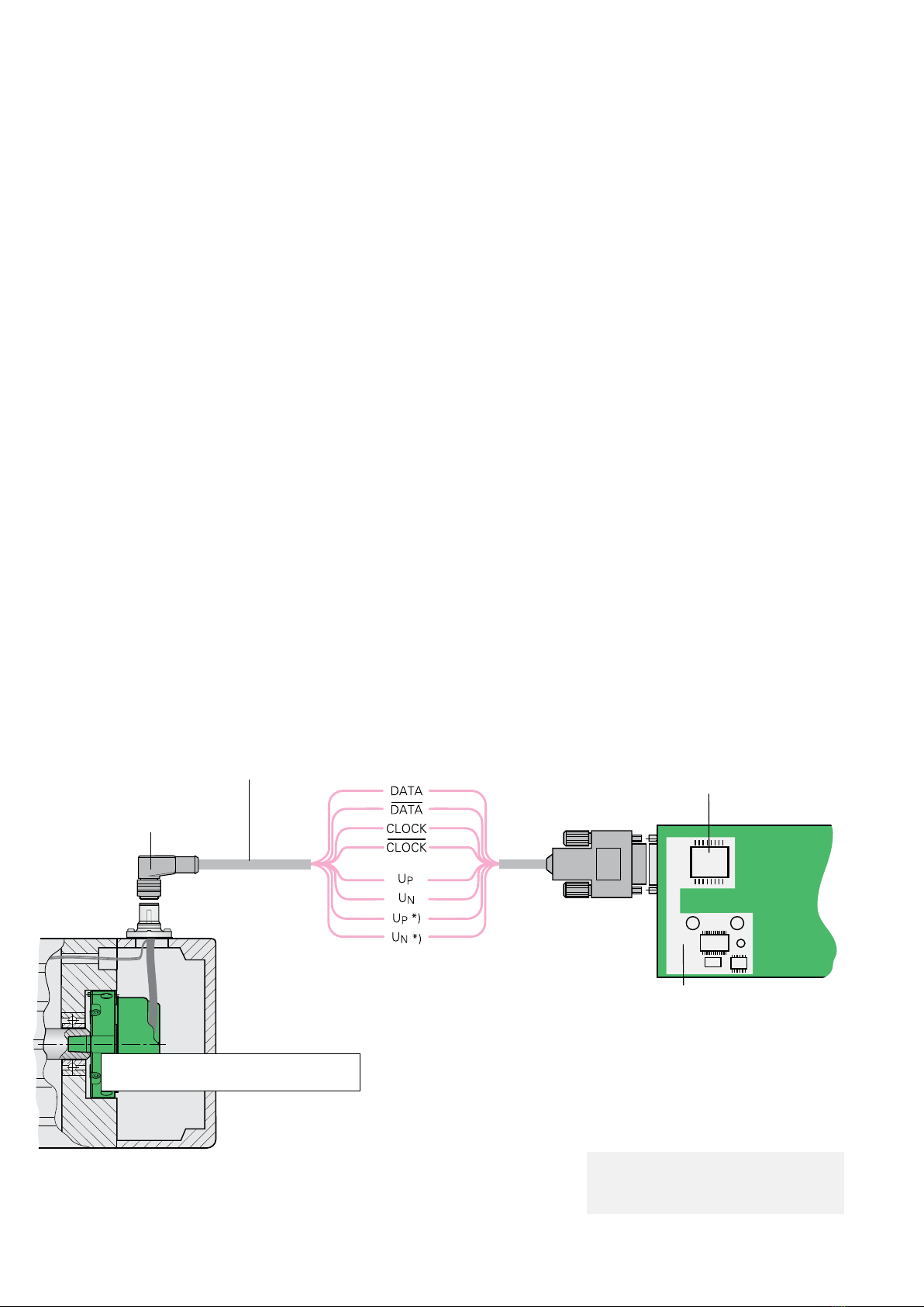
–The bidirectional interface
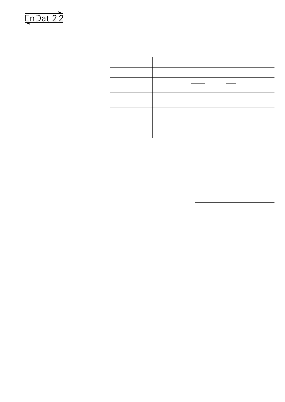
Interface EnDat serial bidirectional
Data transfer Position values, parameters and additional data
Data input Differential line receiver according to EIA standard RS 485 for
the signals CLOCK, CLOCK, DATA and DATA
Data output Differential line driver according to EIA standard RS 485 for
DATA and DATA signals
Position values Ascending during traverse in direction of arrow (see dimensions
of the encoders)
Incremental signals Depends on encoder
»1 VPP
, TTL, HTL (see the respective incremental signals)
The EnDat interface is a digital,
bidirectional interface for encoders. It is
capable both of transmitting position
values as well as transmitting or updating
information stored in the encoder, or saving
new information. Thanks to the serial
transmission method, only four signal
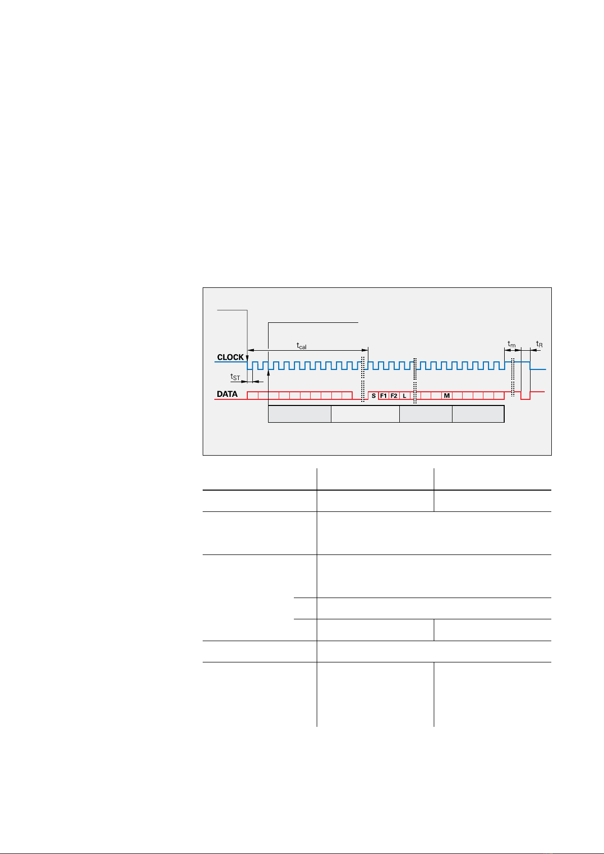
lines are required. The data is transmitted
in synchronism with the clock signal from
the subsequent electronics. The type of
transmission (position values, parameters,
diagnostics, etc.) is selected through mode
commands that the subsequent electronics
send to the encoder. Some functions are
available only with EnDat 2.2 mode
commands.
History and compatibility
The EnDat 2.1 interface available since the
mid-90s has since been upgraded to the
EnDat 2.2 version (recommended for new
applications). EnDat 2.2 is compatible in its
communication, command set and time
conditions with version 2.1, but also offers
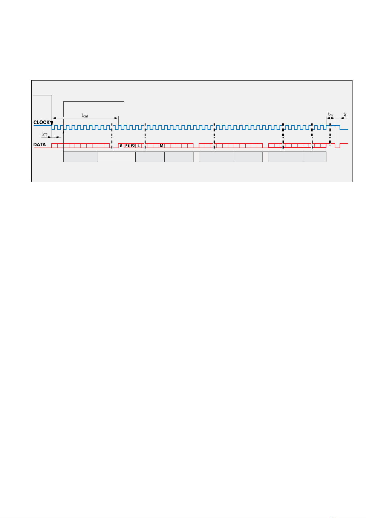
significant advantages. It makes it possible,
for example, to transfer additional data (e.g.
sensor values, diagnostics, etc.) with the
position value without sending a separate
request for it. This permits support of
additional encoder types (e.g. with battery
buffer, incremental encoders, etc.). The
interface protocol was expanded and the
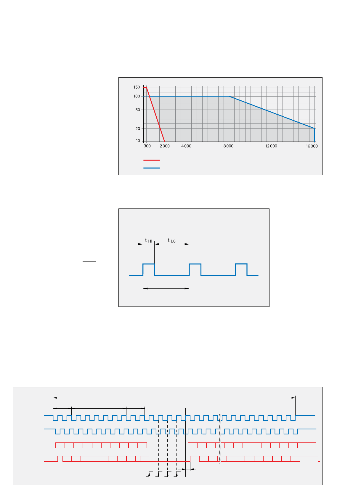
time conditions (clock frequency,
processing time, recovery time) were
optimized.
Supported encoder types
The following encoder types are currently
supported by the EnDat 2.2 interface (this
information can be read out from the
encoder’s memory area):
• Incremental linear encoder
• Absolute linear encoder
• Rotational incremental singleturn
encoder
• Rotational absolute singleturn encoder
• Multiturn rotary encoder
• Multiturn rotary encoder with battery
buffer
In some cases, parameters must be
interpreted differently for the various
encoder models (see EnDat Specifications)
or EnDat additional data must be
processed (e.g. incremental or battery-
buffered encoders).
Order designations
The order designations define the central
specifications and give information about:
• Typical voltage supply range
• Command set
• Availability of incremental signals
• Maximum clock frequency
The second character of the order
designation identifies the interface
generation. For encoders of the current
generation the order designation can be
read out from the encoder memory.
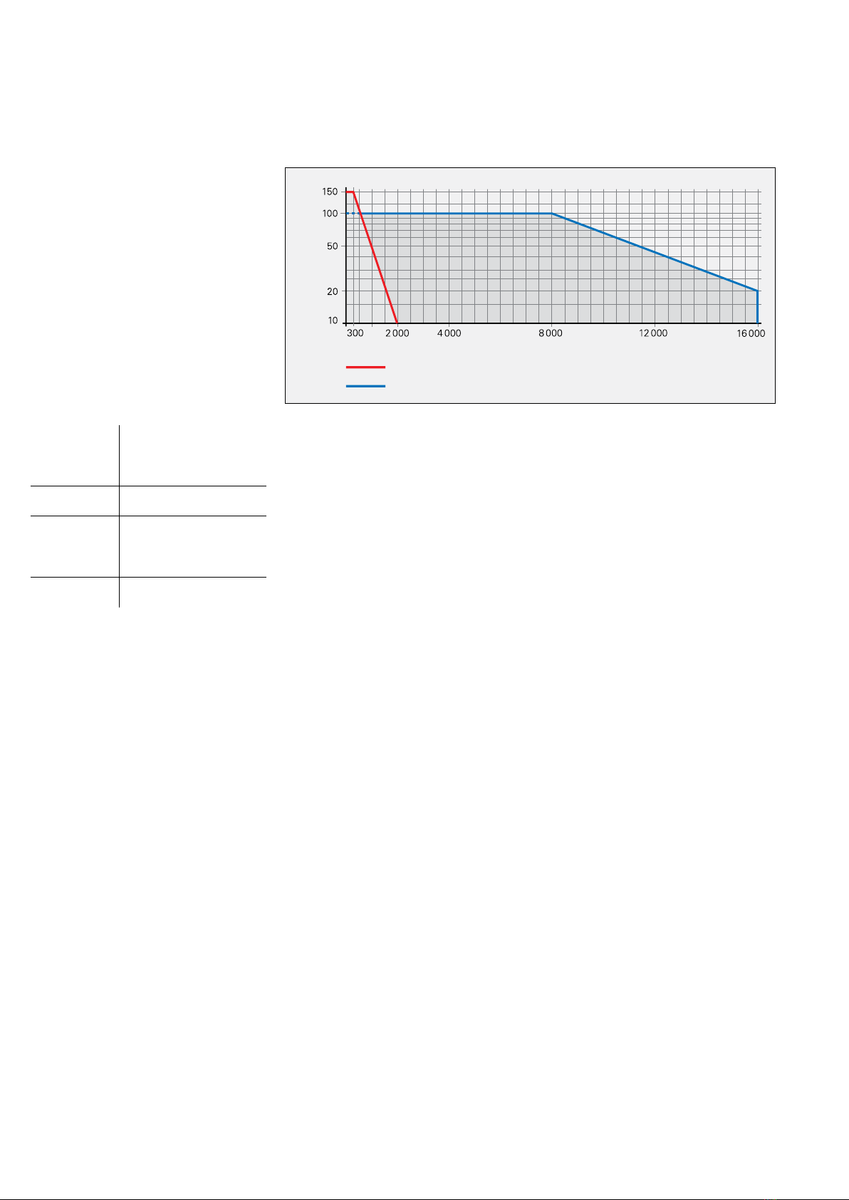
Incremental signals
Some encoders also provide incremental
signals. These are usually used to increase
the resolution of the position value, or to
serve a second subsequent electronics
unit. Current generations of encoders have
a high internal resolution, and therefore no
longer need to provide incremental signals.
The order designation indicates whether an
encoder outputs incremental signals:
• EnDat01 With 1 VPP incremental signals
• EnDatH With HTL incremental signals
• EnDatT With TTL incremental signals
• EnDat21 Without incremental signals
• EnDat02 With 1 VPP incremental signals
• EnDat22 Without incremental signals
Note on EnDat01/02:
The signal period is stored in the encoder
memory.
Voltage supply
The typical voltage supply of the encoders
depends on the interface:
EnDat01
EnDat21
5 V ± 0.25 V
EnDat02
EnDat22
3.6 V to 5.25 V or 14 V
EnDatH 10 V to 30 V
EnDatT 4.75 V to 30 V
Exceptions are documented in the
Specifications.
Command set
The command set describes the available
mode commands, which define the
exchange of information between the
encoder and the subsequent electronics.
The EnDat 2.2 command set includes all
EnDat 2.1 mode commands. In addition,
EnDat 2.2 permits further mode com-
mands for the selection of additional data,
and makes memory accesses possible
even in a closed control loop. When a
mode command from the EnDat 2.2
command set is transmitted to an encoder
that only supports the EnDat 2.1 command
set, an error message is generated. The
supported command set is stored in the
encoder’s memory area:
• EnDat01/21/H/T Command set 2.1
or 2.2
• EnDat02/22 Command set 2.2

4
Cable length [m]
Clock frequency [kHz]
EnDat 2.1; EnDat 2.2 without propagation-delay compensation
EnDat 2.2 with propagation-delay compensation
Under certain conditions, cable lengths up to 300 m are possible after consultation with
HEIDENHAIN
Additional data
One or two items of additional data can be
appended to the position value, depending
on the type of transmission (selection via
MRS code). The additional data supported
by the respective encoder are saved in the
encoder parameters.
The additional data contains:
Status information, addresses and data
• WRN – warnings
• RM – reference mark
• Busy – parameter request
Additional data 1
• Diagnostics
• Position value 2
• Memory parameters
• MRS-code acknowledgment
• Test values
• Temperature
• Additional sensors
Additional data 2
• Commutation
• Acceleration
• Limit position signals
• Asynchronous position value
• Operating status error sources
• Timestamp
Clock frequency
The clock frequency is variable—depending
on the cable length (max. 150 m)—
between 100 kHz and 2 MHz. With
propagation-delay compensation in the
subsequent electronics, either clock
frequencies up to 16 MHz are possible or
cable lengths up to 100 m. For EnDat
encoders with order designation EnDat x2,
the maximum clock frequency is stored in
the encoder memory. For all other encoders
the maximum clock frequency is 2 MHz.
Propagation-delay compensation is provid-
ed only for order designations EnDat 21
and EnDat 22; for EnDat 02, see the note
below.
EnDat01
EnDatT
EnDatH
≤2 MHz (see “without
propagation-delay com-
pensation” in the diagram)
EnDat21 ≤2 MHz
EnDat02 ≤2 MHz or
≤8 MHz or 16 MHz
(see note)
EnDat22 ≤8 MHz or 16 MHz
Transmission frequencies up to 16 MHz in
combination with large cable lengths place
high technological demands on the cable.
Due to the data transfer technology, the
adapter cable connected directly to the
encoder must not be longer than 20 m.
Greater cable lengths can be realized with
an adapter cable no longer than 6 m and
an extension cable. As a rule, the entire
transmission path must be designed for
the respective clock frequency.
Note on EnDat02
EnDat02 encoders can feature a pluggable
cable assembly. In choosing the version
of the adapter cable, the customer also
decides whether the encoder will be
operated with incremental signals or
without them. This also affects the
maximum possible clock frequency. For
adapter cables with incremental signals the
clock frequency is limited to at most
2 MHz; see EnDat01. For adapter cables
without incremental signals the clock
frequency can be up to 16 MHz. The exact
values are stored in the encoder’s memory.
Position values
The position value can be transmitted with
or without additional data.
It is not transmitted to the subsequent
electronics until after the calculation time
tcal has passed. The calculation time is
ascertained at the highest clock frequency
permissible for the encoder, but at no
greater than 8 MHz.
Only the required number of bits is trans-
ferred for the position value. The bit num-
ber depends on the respective encoder
and can be read out from the encoder for
automatic parameterization.
Typical operating modes
Operating mode EnDat 2.1: This mode is
for encoders that provide additional incre-
mental signals. The absolute position is
read out once simultaneously with the
incremental position and both are used to
calculate the position value. Otherwise, the
position value in the control loop is formed
on the basis of the incremental signals.
Only EnDat 2.1 mode commands are used.
Operating mode EnDat 2.2: This mode is
for purely serial encoders. The position
value is read out from the encoder in each
control cycle. EnDat 2.2 mode commands
are typically used to read out the position
value. EnDat 2.1 mode commands are
typically used to read and write parameters
after switch-on.
The EnDat 2.2 interface can interrogate the
position and additional data, and also per-
form functions (e.g. read/write parameters,
reset error messages, etc.), all within the
closed loop.

5
Absolute encoder Subsequent electronics
»1 VPP A*)
»1 VPP B*)
Operating
parameters
Operating
status
Parameters
of the OEM
Parameters of the encoder
manufacturer for
EnDat 2.1 EnDat 2.2
*) Depends on encod-
er, example repre-
sentation for 1 VPP
Absolute
position value
EnDat interface
Incremental
signals *)
Memory areas
The encoder provides several memory
areas for parameters. These can be read
from by the subsequent electronics, and
some can be written to by the encoder
manufacturer, the OEM, or even the end
user. The parameter data are stored in a
permanent memory. This memory permits
only a limited number of write access
events and is not designed for cyclic data
storage. Certain memory areas can be
write-protected (this can only be reset by
the encoder manufacturer).
Parameters are saved in various memory
areas, e.g.:
• Encoder-specific information
• Information of the OEM
(e.g. “electronic ID label” of the motor)
• Operating parameters (datum shift,
instruction, etc.)
• Operating status (alarm or warning
messages)
Monitoring and diagnostic functions of
the EnDat interface make a detailed
inspection of the encoder possible.
• Error messages
• Warnings
• Online diagnostics based on valuation
numbers (EnDat 2.2)
• Mounting interface
Input circuitry of
subsequent electronics
Dimensioning
IC1= RS 485 differential line receiver
and driver
Z0= 120
Encoder Subsequent electronics
1 VPP
Data transfer
Incremental signals
Depends on encoder
(e.g. 1 VPP)
Functional safety – Basic principle
EnDat 2.2 strictly supports the use of
encoders in safety-related applications. The
DIN EN ISO 13 849-1 (previously EN 954-1),
EN 61508 and EN 61800-5-2 standards
serve as the foundation. These standards
describe the assessment of safety-related
systems, for example based on the failure
probabilities of integrated components and
subsystems. The modular approach helps
manufacturers of safety-related systems to
implement their complete systems,
because they can begin with prequalified
subsystems.
For more information, see “Functional
safety” at www.endat.de
Other manuals for EnDat 2.2
1
Other HEIDENHAIN Recording Equipment manuals