Heinz Walz ULM-500 User manual


ULM-500
ENTER CALIBRATION FACTOR
SAVE
OK ESC
4x
finish with:
ESC
3x
finish with:
enter Main Menu
MENU
MENU
MENU
MENU
MENU
chose
Display
chose
Sensors
chose
Calibration
chose
PAR
Sensors
chose
Connector
mark
connected
sensor with:
MENU
ESC MENU
adjustment with:
also chose unit
SAVE
OK ESC
4x
finish with:
SAVE
OK ESCESC
4x
finish with:
ESC
3x
finish with:
ESCESC
3x
finish with:
enter Main Menu
MENU
MENU
MENU
MENU
MENU
chose
Display
chose
Sensors
chose
Calibration
chose
PAR
Sensors
chose
Connector
mark
connected
sensor with:
MENU
ESC MENU
adjustment with:
also chose unit
enter Main Menu
MENUMENU
MENUMENU
MENUMENU
MENUMENU
MENUMENU
chose
Display
chose
Display
chose
Display
chose
Sensors
chose
Sensors
chose
Sensors
chose
Calibration
chose
PAR
Sensors
chose
PAR
Sensors
chose
Connector
chose
Connector
mark
connected
sensor with:
MENU
mark
connected
sensor with:
MENUMENUMENUMENU
ESC MENU
adjustment with:
also chose unit
ESC MENUESCESC MENUMENU
adjustment with:
also chose unit


CONTENTS
1Safety Instructions .......................................................................1
2Assembling the ULM-500............................................................2
2.1 The Keypad...............................................................................5
3Input of Calibration Values.........................................................6
3.1 Order of measuring windows....................................................8
3.1.1 The PAR Window............................................................... 9
3.1.2 The Leaf-Clip Window.......................................................9
3.1.3 The Air Sensor Window ................................................... 10
3.1.4 The Chart Window............................................................ 10
3.2 Before the Measurement.........................................................12
3.2.1 Changing Calibration Factors........................................... 14
3.2.2 Measure Settings...............................................................15
3.2.3 Device Settings.................................................................18
3.2.4 Applications...................................................................... 19
3.2.5 User Applications ............................................................. 21
3.2.6 Info.................................................................................... 22
3.2.7 Memory............................................................................. 22
4Connection to the Computer.....................................................23
5Operating the ULM-500 via WinControl-3............................. 24
5.1 The Initial Tab / Chart Tab .....................................................24
5.1.1 Main Menu Bar - Box (1) ................................................. 25
5.1.2 Data Management and Graph Design - Box (2) ...............26
5.1.3 Sidebar - Box (3)............................................................... 28
5.1.4 Online Values - Box (4)....................................................30
5.1.5 Triggered Data - Box (5)...................................................30
5.1.6 Store Data Point - Box (6) ................................................30

CONTENTS
5.1.7 Protocols - Box (7)............................................................30
5.1.8 Graph, Data and Fluorometer Settings Tabs - Box (8)..... 31
5.1.9 Axis Control - Box (9)...................................................... 31
5.1.10 Ordinate Selection and Text Field - Box (10)...................32
5.1.11 Chart - Selecting Data.......................................................33
5.2 The Report Tab ....................................................................... 34
5.2.1 Data Management and Graph Design - Box (2) ...............35
5.2.2 The Report Data Field – Box (11) .................................... 37
5.3 The Memory Tab ....................................................................37
5.3.1 Box (12) – Memory Operations........................................ 38
5.4 The Settings Tab ..................................................................... 39
5.4.1 Chosen Instrument and Reset button - Box (12)............... 39
5.4.2 Instrument Settings - Box (13).......................................... 40
5.4.3 Instrument Information - Box (14) ...................................42
5.4.4 System Settings – Box (15)...............................................43
6Technical Specifications*........................................................... 45
7Warranty Conditions.................................................................47

SAFETY INSTRUCTIONS
1
1Safety Instructions
Instructions. Read all the safety instructions and operating
instructions thoroughly before using the device for the first time. Keep
these safety instructions and operating instructions somewhere safe in
case you need to refer to them again in the future.
Safety warnings. Pay heed to safety warnings on the device and in
the operating instructions. Follow the instructions for operation and use
of the device in every respect.
Temperature. Do not install the device near any heat sources such
as radiators, hot-air dryers, ovens, etc. Do not place naked flame
sources, such as lighted candles or Bunsen burners, on or near the
device.
Moisture. Keep this device out of the rain and away from moisture.
Do not expose the apparatus to dripping or splashing and do not place
any object filled with liquid, such as drinking vessels, beakers or test
tubes, on or close to the device. Never use the device near water, for
example near a sink.
Solid objects. Take great care to ensure that no sharp objects
penetrate inside the device through openings of the casing.
Service. Do not open the casing. There are no user serviceable parts
inside. Refer all servicing to qualified service personnel. Servicing is
required when the apparatus has been damaged in any way, e.g., by
exposure to wet conditions, excessive heat, or has been dropped.
Power source. Connect the device only to the 5 Volt power source
of a USB socket of a computer using the USB cable supplied with the
device. Run the USB cable so that no one can step on it and nothing can
rest on or against it.
Device not in use. If you are not going to use the device for some
time, remove the plug from the socket and remover the batteries..
Cleaning. Clean only with dry cloth.

THE ULM-500 INSTRUMENT
2Assembling the ULM-500
The ULM-500 can be connected with sensors via BNC standard
connectors (Bayonet Neill-Concelman, PAR #1 and #2) shown in the
image below:
Fig. 1 configuration of ULM-500 sensor connectors
After connecting new sensors to the ULM-500 please do not forget
to check the calibration factors needed! (Chapter 2)
Two further optional accessories used mainly on Monitoring-PAMs,
the leaf-clip holder (e.g. MONITORING-LC JUNIOR-B or MINI-
PAM-LC 2030-B) and the Air-Sensor (Humidity and Temperature – not
available yet) can be connected via the panel plugs 1 and 2 (located in-
between the BNC connectors). Insert batteries like indicated in figure 2.
Open the battery compartment by pushing the release of the back cover.
2

THE ULM-500 INSTRUMENT
Insert four AAA batteries (1.5 V) with the correct and polarity
(marked in the compartment).
Fig. 2 Polarity of the batteries
Close the battery compartment completely again before using.
NiCd or NiMH cells are also possible but can not be charged when
inserted. Under extreme low temperature (0°C) 1.5V Li-cells are
recommended. When placing the ULM-500 into storage for a longer
time, please make sure that no batteries are inserted.
3

THE ULM-500 INSTRUMENT
Fig. 3 Connecting sensors to the ULM-500 (here: BNC to PAR #1)
To connect a male BNC plug to PAR #1 or #2 push and carefully
right-turn the connector as shown in Fig. 3 The connectors used for the
panel plugs 1 and 2 need to be screwed to get good contact with the
accessory sensors.
4

THE ULM-500 INSTRUMENT
5
2.1 The Keypad
The ULM-500 keypad offers six buttons which from which have
more than one function.
ON/OFF switches the instrument on or off when held for more than
3 seconds. Additionally the display illumination can be switched on
with this button by pressing it shortly while the ULM-500 is already
switched on. Illumination will switch off automatically after 40 seconds
to save battery power.
SAVE freezes the display during a measurement and stores the
recent data (HOLD is shown in the lower left display corner). A new
line in the report is produced.
ESC is normally used to navigate back to the previous menu item
when it is pressed once shortly. When being deeper in the settings menu
ESC can be held for some seconds to go completely back to the starting
window.
MENU is used to enter the menu for changing settings. The key is
also used as an “enter” button to confirm settings. The arrow indicates
that it moves forward in a menu or on a screen.
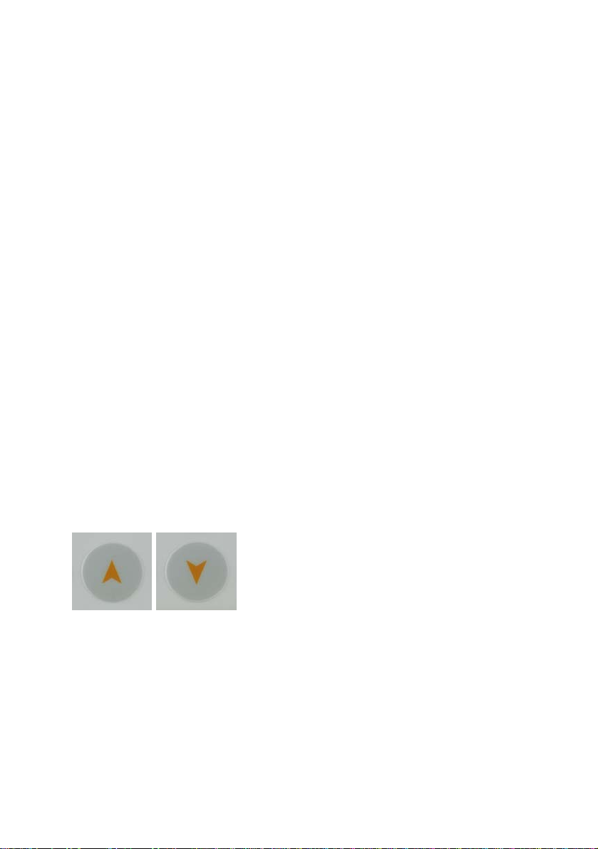
UP/DOWN buttons are used for the navigation inside a menu. They
control the cursor position (which is displayed on the screen as inverted
field).
MENU AND OPERATION
6
3Input of Calibration Values
After having connected all necessary sensors to the ULM-500 the
instrument needs Calibration factors before the first accurate
measurement can start. Only leaf-clips that like the JUNIOR-B, 2030-B
or 2060-M do not need calibration factors. Nevertheless they might
need to be calibrated from time to time as it is necessary for all sensors.
Touch the “ON” key and the instrument will wake up with a short
beep and show the start screen - similar to the screen shown below.
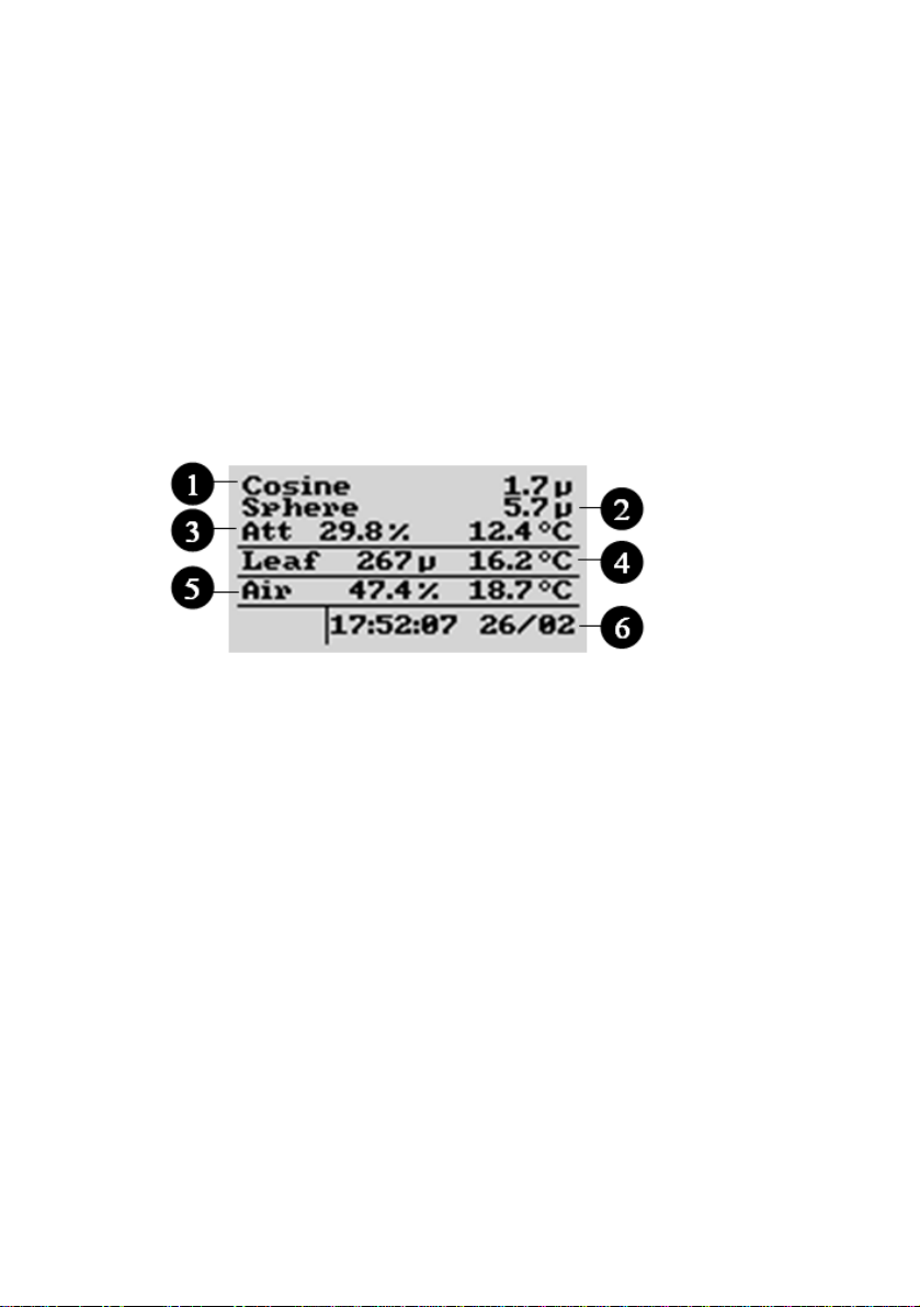
Fig. 4 Starting screen with two PAR sensors and a leaf clip connected.
Line 1 and 2 show the chosen sensors connected via BNC. 3 is the
perceptual difference between these sensors. 4 and 5 are sensors
connected via the panel plugs. 6 is the recent time and date in the
instrument
The first two lines of the start-screen show the values measured
with the sensors connected to PAR #1 and PAR #2 (second line).
The “µ” is used instead of the PAR unit µmol/m-2s-1 (via
WinControl-3 the shown unit can be exchanged against a W (for Wm-2)
in case a pyranometer for the measurement of the solar irradiance is
connected to the ULM-500).
In the third line “Att” is the attenuation index as perceptual loss of
PAR intensity between sensors connected via PAR #1 and PAR #2. The
third line also shows the internal temperature of the ULM-500 (this
MENU AND OPERATION
7
value may differ from the ambient temperature when the ULM-500 is
operated in sunlight).
The parameter “Air” in the fifth line of the start screen refers to a
humidity sensor that will be available in the near future. The first value
shown is the relative humidity calculated from the temperature sensor
built in this “air” sensor and the absolute humidity measured (this
sensor is connected via panel plug 2 – Fig 1).
In the last line the recent time and date used in the instrument is
indicated (these values can be set via the ULM-500 or automatically via
WinControl-3 software when the ULM-500 is connected).
When switching the instrument on for the first time, there is only a
standard set of calibration values for typical PAR sensors stored. The
sensor names can be defined via WinControl-3 software (chapter 4) and
also the most important calibration factors can be entered via
WinControl-3 but also the ULM-500 directly (in this case the sensor
names can not be changed).
.The ULM-500 will remember the last screen used, when it is
switched on the next time.
There are four more screens available in
the ULM-500, each focuses on a different
set of parameters, accessories or sensors.
By using the “up” or “down” button one
can switch from one screen to another beginning with the normal
starting screen. After switching off the ULM-500 it will automatically
show up with the last measuring window used after switching it on
again..
MENU AND OPERATION
8
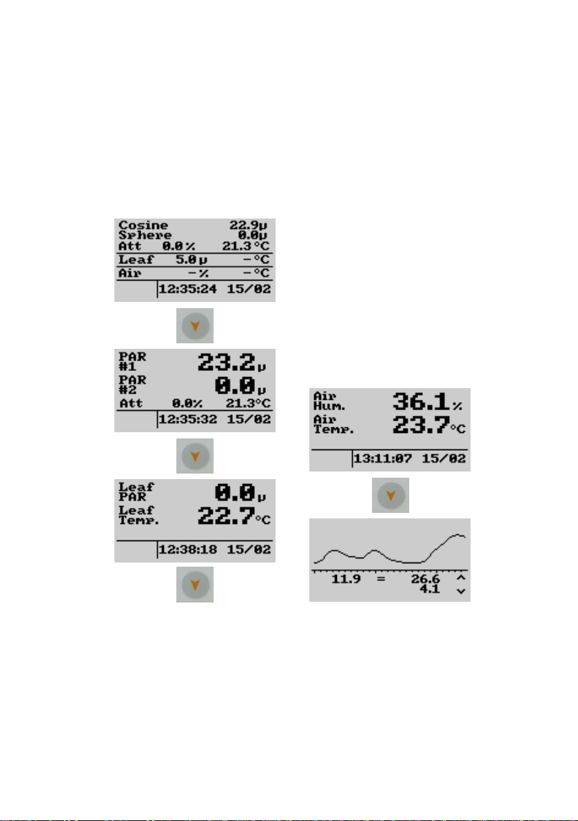
3.1 Order of measuring windows.
In the image below the order of measuring windows is shown when
the “down” arrow button is used. Scrolling through these windows is
also possible by using the “up” arrow button to navigate in the opposite
direction.
1
2
3
4
5
From here the instrument can be switched off at any time by
pressing the “off” button for three seconds (pressing this button once
shortly will activate the display illumination for 5 mins). From this
measure mode, the menu can be entered by pressing “MENU” on the
keypad of the ULM-500.
MENU AND OPERATION
9
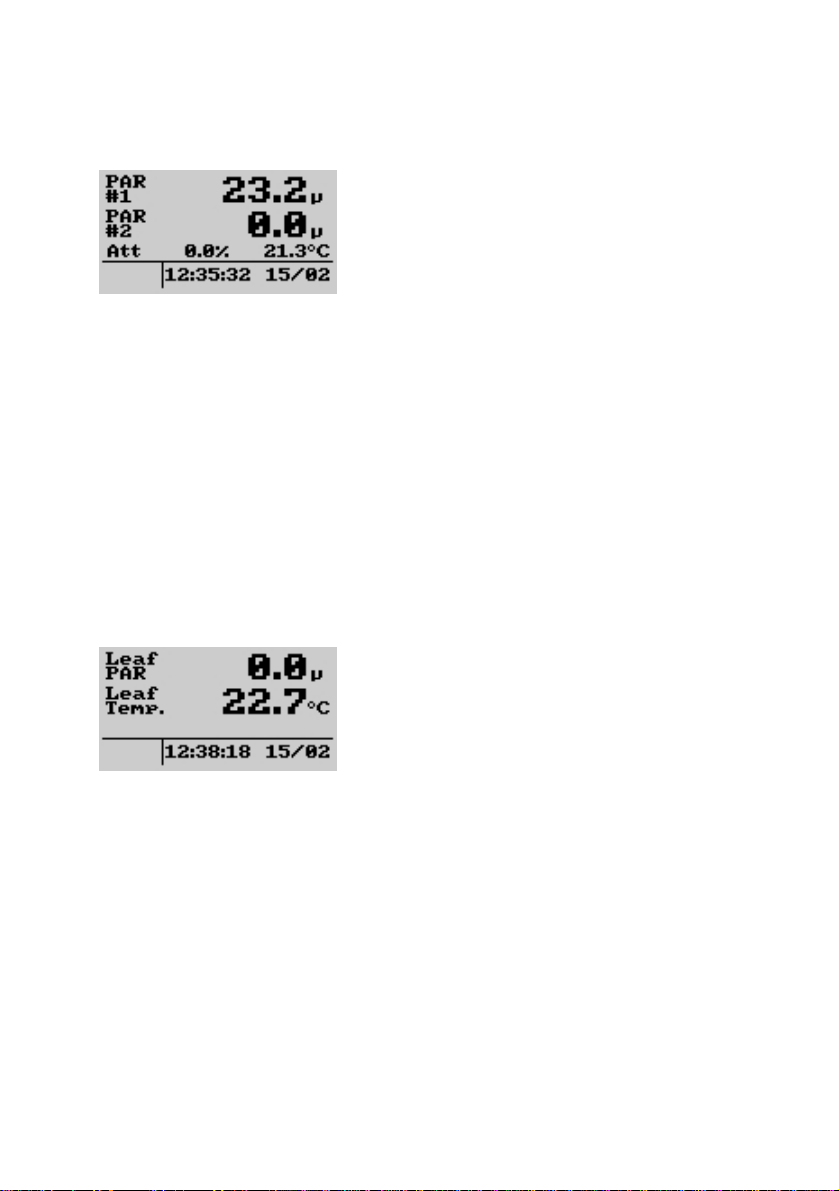
3.1.1 The PAR Window
The PAR window displays values
coming from sensors connected via the
BNC connectors to PAR #1 and #2 (see
also Fig. 1). In this case it is of great
importance that the calibration factors for
the sensors are set correctly (please also read chapter 3.2 and 3.2.1). The
parameter “Att” in the third line stands for the attenuation index that is
calculated as perceptual difference between the both sensors connected
to PAR #1 and #2. At the end of the line, the internal temperature of the
instrument is shown. Please note that this temperature may differ from
the ambient temperature when the ULM-500 is operated e.g. in sunlight.
Below date and time stored in the instrument are shown (can be
synchronized with the system time of a computer via WinControl-3
software – chapter 5).
3.1.2 The Leaf-Clip Window
In case the 2030-B leaf-clip holder or
the sensor set 2060-M shall be used for
light and temperature measurement with
the ULM-500, an optional adapter cable
(2030-B/ULM) is necessary. 2030-B and
2060-M carry a thermocouple and a light sensor and are normally used
together with the MINI-PAM, PAM-2500 or JUNIOR-PAM. These two
parameters are shown in bigger letters in the leaf-clip screen.
Additionally also the date and time is displayed.

MENU AND OPERATION
10
3.1.3 The Air Sensor Window
The “Air” sensor is not yet available.
3.1.4 The Chart Window
In the chart window the recent changes
of the incident radiation can be observed
(PAR #1 channel). Maximum, minimum
and average values (left) are shown in
addition to the graphic. This screen is also
used for the triggered measurement (chapter 3.2.2). The timeline
displayed can be switched from 1.2 to 2.4 seconds in the measure
settings “chart” in chapter 3.2.2.
Fig. 5 Typical shape of light flashes from different light sources. The
right saturating pulse has been recorded from a Diving-PAM which
is using a halogen lamp; the left curve is derived from a PAM-2500
working with fast red LEDs. The curves are shown normalized to
fit them into the chart screen. The measured amplitude is displayed
as value below the chart.
When the trigger has been activated the chart runs as long as the trigger
level is not yet reached. In case the ULM-500 registers a fast increase of

MENU AND OPERATION
11
the radiation the graphic will stop so that the shape of the flash and its
values can be evaluated on the display.
Also without having the trigger activated the chart can be stopped.
Pressing “SAVE” freezes the chart. The chart window now displays the
message “HOLD” in the lower left corner. The chart can be released
again by pressing “ESC” and the trigger is still activated again (if it has
been activated before).
The graphic is not saved; a continuous record of the radiation can be
achieved when the ULM-500 is used together with the WinControl-3
software. In this case the recording time is not limited.
MENU AND OPERATION
12
3.2 Before the Measurement
Please always check the calibration values for the chosen sensors
before the measurement
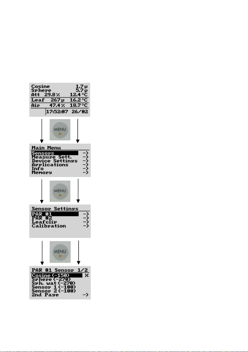
Checking the sensor settings for the PAR
channels is really easy – starting e.g. with #1
from any of the parameter screens pressing
“Menu” will switch one level deeper into the
calibration settings. To make the navigation
easier, the ULM-500 remembers the position
in the menu that you chose last time and
displays it inverted. Moving the active field is
done by using the “up” and “down” arrow
buttons.
With the “ESC” key the display jumps one
step back in the menu. Going completely back
to the start screen is possible by pressing the
“ESC” button for 3 seconds from any position
in the menu.
At the end of the navigation a window
with the stored sensor types/names and
settings appear (lowest image). In the case
shown, the setting for the PAR channel #1 is
shown.
The “X” at the end of a line marks the
sensor chosen for channel #1 is named
“Cosine” in this case its calibration factor is -
150 (shown as rounded value - can be edited
in the “PAR Calib.” window described below)

MENU AND OPERATION
13
If another sensor (already stored) shall be chosen, the cursor
(inverted field) can be moved up or down and entered by pressing
“MENU” once again. Also a second page with five more sensors can be
chosen (2nd Page).
Under “Leafclip” also the optional leaf-clip holder connected to the
ULM-500 can be defined. In the case of a MINI-PAM or PAM-2500
leaf clip holder (2030-B) or the sensor set 2060-M an additional adapter
cable is necessary (2030-B/ULM) and the setting has to be “MINI-
PAM LC”. When a leaf clip from a JUNIOR-PAM shall be connected
(JUNIOR-B), “MONITORING LC” has to be chosen to get correct
measurements. This can also be done via the WinControl-3 software
(chapter 5.4).

MENU AND OPERATION
3.2.1 Changing Calibration Factors
Connecting a new or different
radiation sensor normally needs a
change of calibration factors prior to
the measurement.
Please use the “up” and “down”
arrow buttons, “Menu” and “ESC” as
described in the chapter 3.1.1 to
navigate in the ULM-500 menu.
Going completely back to the start
screen is possible by pressing the
“ESC” button for 3 seconds.
In the “PAR Calib.” window the
calibration factors for each radiation
sensors can be edited (this can also be
a pyranometer). Just move the
inverted field (cursor) to the desired
line (“up” and “down”), afterwards
press “MENU” to enter the
calibration factor digits. The value
can be changed digit by digit - “up” and “down” increase or
decrease the digit. “MENU” moves the cursor to the next digit of
the calibration factor. Pressing “ESC” for 3 seconds moves to the
very start of the settings menu and confirms the changed settings.
The ULM-500 stores up to 10 calibration factors shown on
two pages in the menu. While the factors themselves can be edited
directly in the ULM-500, it is not possible to change the sensor
names in the field without using a computer. This can only be
done with the help of the WinControl-3 software that has been
14
Table of contents
Other Heinz Walz Measuring Instrument manuals


