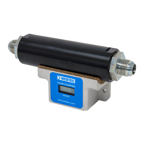
WEBTEC FlowHUB Series User manual

FlowHUB Series
User Manual
FlowHUB-Reihe
Bedienungsanleitung
Série FlowHUB
Manuel d’utilisation
Serie FlowHUB
Manual del usuario
Webtec Products Limited
www.webtecproducts.com


1
English
Introduction
The FlowHUB is ideal for condition monitoring, test stands and closed loop control applications both for uid power and
lubrication systems. The FlowHUB can measure and display ow and temperature readings as well as switch and transmit
ow values. This enables a system designer to trigger alarms, shutoffs and transmit real-time values to a PLC using just
one component, instead of up to six which might have been required conventionally. This represents a signicant cost
saving in terms of reduced complexity of wiring and far fewer components.
It is available in ve ow ranges from 1 to 360 lpm (0.25 to 100 US gpm) and in two pressure ranges 210 and 420 bar
(3,000 and 6,000 psi). The FlowHUB is available in three versions - ‘Switch’, ‘Transmitter’ and ‘Ultimate’, all three versions
have built in temperature measurement and a large bright digital display.
The ‘Switch’ version provides two congurable switched outputs; the level, time delay, sense (above/below) and normal
mode (normally closed/normally open) can all be freely congured. Each switch is independent and can switch up to
500 mA. The ‘Transmitter’ version provides a conditioned analogue output either 0 - 5 Volts or 4 - 20 mA - full scale is
congurable to any maximum ow. The ‘Ultimate’ version has both the switches and transmitter and the highest pressure
rating of 420 bar (6,000 psi) as well as an enhanced response time of 50 ms.
Before rst operating the equipment read the whole of these instructions. Safety may be impaired if they are not followed.
Webtec have been designing and manufacturing ow meters and hydraulics components for over 40 years. We operate
within a Quality Management System that complies with the requirements of BS EN ISO 9001:2000 which is externally
audited and certicated each year. Beyond compliance to the standard, Webtec is committed to continually improving in
everything we do; with particular emphasis on understanding what matters to our customers and suppliers, and designing
our systems and work to meet their needs. We are always keen to hear from customer who may have special requirements
not covered by our standard ranges.

English
All FlowHUB’s work on the same theory - the uid ow is used to move a magnet which is mounted within a piston,
the distance moved is proportional to the ow rate. This movement is measured by a sensitive magnetic device. The
on-board electronics condition the signal and convert the linear movement to uid ow. The FlowHUB also allows
unmeasured ow in the reverse direction - when reverse ow is present the display will show ‘-EE-’.
A temperature probe mounted in the main body provides an indication of the uid temperature. Options on the FlowHUB
include, analogue output - either 4 - 20 mA or 0 - 5 volt, two programmable switches or both options tted.
Note. If the current loop is open circuit then the left LED will illuminate either red or amber.
All FlowHUB’s are designed to work with oil at 21 cSt as standard. Special calibration is available over a custom ow
range or at a different viscosity, please contact sales to discuss your application.
Basic operation
2

English
Functional Specication
lFlow range: see model conguration
lPressure range: see model conguration
lAmbient operating temperature: - 5 to 40 °C
lFluid type: hydraulic oil
lFluid temperature: 5 to 90 °C
lAccuracy: ± 3% of full scale at 21 cSt (higher
accuracy on request)
lRepeatability: better than ± 1%
lResponse time: 150 ms (Switch and Transmitter),
50 ms (Ultimate)
lProtection: designed to meet IP64
Electrical specication
lSupply voltage: 15 to 30 VDC class 2 supply only
lTypical current: 35 mA
lMaximum current excluding switch current: 60 mA
lSwitch current: 500 mA per switch max.
lSwitch Voltage: supply voltage - 0.5 V
lConnector type: M12 - 5 pin male
lVoltage output: minimum load = 10K Ohms
lCurrent output: maximum load = (supply voltage x
46) - 200 ohms
lRecommended cable: screened cable, 5 x 0.25(2)
(24AWG)
1 - + supply
2 - switch 1 *
3 - GND
4 - switch 2 *
5 - Analogue out: either 0 - 5V or
4 - 20 mA *
* These are options according to model and
may not be operational.
1
2
3
4
5
Pin Connection Details
3

4
English
Installation guidance
FlowHUB has built-in ow conditioners so the normal recommended length of 10 Ø of straight tube can be eliminated.
Inlet and outlet connections should always have a similar bore size to that of the ow meter to prevent venturi or
constriction effects.
All hydraulic connections should be made by a suitable qualied personnel only. If ow meter is connected by exible
hose, the weight of the product should not be taken by the hydraulic connections.
Filtration - it is recommended that a 25 micron lter is installed in the hydraulic circuit prior to the ow meter.
The FlowHUB can be installed in any orientation.
The unit contains a sensitive magnetic device it is therefore recommend to mount away from strong magnetic elds and
large ferrous objects, a distance of 80mm (3.25”) is recommend. For this reason it is also recommend to use only the
adaptors supplied as different shaped adaptors can effect the readings.
Care should be taken to ensure that the FlowHUB is installed in a position which is not subjected to excessive pulsation
as this can cause incorrect readings. For heavy-duty applications, for example installation close to a piston pump, consult
the Webtec Products sales ofce.
This FlowHUB is for indoor use only - do not install in wet areas or outside without the appropriate additional protection.
The FlowHUB will allow reverse ow but it will not measure the ow rate. The pressure drop in reverse ow is considerably
higher then that in forward ow. - see technical information
The performance of the FlowHUB can be affected by the viscosity of the uid measured. All units are designed to meet
the specication at a viscosity of 21cSt, which is a typical kinematic viscosity for a hydraulic uid operating at 50°C.
N.B. The electronics enclosure must be protected from the ingress of water or other uids - serious malfunction may occur is water enters.
Power connection (pin 1) to include in line fuse for cable protection (1A)
4

English
Installation
Dimensions in Millimetres (Inches)
Down Key
Up Key Enter Key
Display LED 1 LED 2
230.4 (9.07)
41.2 (1.62)100 (3.93)
127.9 (5.03)
54 (2.12)
60 (2.36)
12.0
(0.47)
50 (1.96) A/F
(Each End)
R28.3 (1.11)
5

6
English
The menu structure is divided into three sections
l General viewing level
l Set up level
l Factory menu
The factory menu is for trained Webtec service personnel only. To enter the
set up level menu requires a password - the default password for this is ‘11’.
Menu structure - General viewing level
On this level it is possible to view the values which have been set. According
to the model purchased, features will vary and therefore may not be
available as described.
Press and hold the to display the engineering units - release the key to
return to the current reading.
Press and hold the to alternate the display between the temperature
reading and the temperature units - release the key to return to the current
reading.
Press the key to view the current switch settings.
- Switch one - delay time in milli seconds
- Switch two - delay time in milli seconds
- Switch one - ow level in default engineering units
- Switch two - ow level in default engineering units
When the unit is rst powered on it will display the software version number for approximately 3 seconds then ash the
LED’s, report any errors and then the current ow reading. From this point the menu structure below can be accessed.
6

English
Menu structure - Set up level - General notes
Key
The value can be changed by pressing up or down key. Once the correct value has been achieved pressing the key
enters the value and returns to the main menu. Pressing the up or down keys for longer than 2 seconds will activate a
fast mode which will rapidly change the reading.
Setting switch delay level - this is displayed in seconds with a decimal point. Reading can be changed from 0.10 of a
second up to 10 seconds in 0.01 steps.
Setting switch ow level - the ow level at which the switch will operate can be adjusted from the minimum ow value
to the maximum ow value. These values are dependant on the model.
Set switch type - the switch can be congured to operate above or below the ow level set in the section above.
Set switch sense - the switch can be congured to be normally open or normally closed.
Set ow units - the displayed ow units can be congured to be litres per minute or US gallons per minute. If changed
all switch and analogue output settings will change
Set temperature units - the displayed temperature units can be congured to be degrees Celsius or Fahrenheit.
Set analogue full scale - the ow at which the FlowHUB will give a full scale analogue output can be congured to any
value within the ow range
Set password - the password to enter the setup menu can be changed to any value from 0001 to 9999.
Enter factory set up - only suitably qualied and trained personnel can enter this level - there are no additional user
features.
7

English
Menu Structure
8

Above model number is a FlowHUB Transmitter: Flow range: 8 - 360 lpm, Maximum pressure: 210 bar (3,000 psi),
Temperature: °C, Analogue output: 4 - 20 mA, no switches, 1” BSPP adaptors.
English
Examples
EU ow range (lpm & °C) US ow range (US gpm and °F)
Code 1 Flow range Standard adaptors Code 1 Flow Range Standard adaptors
HF030 1 - 30 1/2” or 3/4” BSPP HF008 0.3 - 8 1 1/16” or 3/4” JIC Male
HF060 2 - 60 1/2” or 3/4” BSPP HF016 0.5 - 16 1 1/16” or 3/4” JIC Male
HF120 4 - 120 3/4” or 1” BSPP HF032 1 - 32 1 1/16” or 1 5/16” JIC Male
HF240 8 - 240 1” BSPP HF064 2 - 64 1 5/16” JIC Male
HF360 8 - 360 1” BSPP HF100 2 - 100 1 5/16” JIC Male
Model conguration
Step 1 - Choose ow range and engineering units
HF360 TRNMA-3 B100V
- -
Code 1 Code 2 Code 3
HF100 TRNMA-3 S100V
- -
Above model number is a FlowHUB Transmitter: Flow range: 2 - 100 US gpm, Maximum pressure: 3000 psi (210 bar),
Temperature: °F, Analogue output: 4 - 20 mA, no switches, 1 5/16” JIC Male adaptors.
EU
US
9

English
Electronic control and maximum pressure options
Code 2 Maximum working pressure Function description
SWTNA-3 210 bar (3,000 psi) Two programmable switches
TRN5V-3 210 bar (3,000 psi) Analogue output 0 - 5 Volt
TRNMA-3 210 bar (3,000 psi) Analogue output 4 - 20 mA
ULT5V-6 420 bar (6,000 psi) Two programmable switches, analogue output 0 - 5 Volt
ULTMA-6 420 bar (6,000 psi) Two programmable switches, analogue output 4 - 20 mA
Adaptors
BSPP options SAE options
Code 3 Description Code 3 Description
B050V 1/2” BSPP S050V 3/4” JIC Male
B075V 3/4” BSPP S075V 1 1/16” JIC Male
B100V 1” BSPP S100V 1 5/16” JIC Male
Step 2 - Choose electronics and maximum pressure
Step 3 - Choose adaptors
Custom congurations are available, please contact sales.
10

English
Technical information
The above specication is met without ‘wet’ calibration if full traceable calibration is required. This is an option and will
incur an additional charge. As standard it is completed at 21 cSt (ISO32 oil at 50°C)
0
020
0 10 20 30 40 50 60 70 80 90 100
10
0
1
2
3
4
5
6
7
20
30
40
50
60
70
80
90
100
110
40 60 80 100 120 140 160 180 200 220 240 260 280 300 320 340 360 380 400
Forward Flow versus Pressure Drop (21 Cst oil at 50°C)
Flow (lpm)
Flow (US gpm)
Pressure Drop (psi)
Pressure Drop (bar)
360 lpm
(100 US gpm)
240 lpm
(64 US gpm)
120 lpm
(32 US gpm)
60 lpm
(16 US gpm)
30 lpm
(8 US gpm)
Construction material
lFlow body: high tensile aluminium 2014 T6
lInternal parts: Brass CZ121, Stainless steel 316,
Steel 212A42
lAdaptors: High pressure - Steel 212A42 zinc plated and clear
trivalent passivate. Standard - Steel 230M07 zinc plated.
lElectronics enclosure: die cast aluminium
11

Flow range Pressure drop Pressure drop
at 1/2 full ow at full ow
360 lpm (100 US gpm) 70 psi @ 180 lpm 260 psi @ 360 lpm
240 lpm (64 US gpm) 40 psi @ 120 lpm 130 psi @ 240 lpm
120 lpm (32 US gpm) 110 psi @ 60 lpm 400 psi @ 120 lpm
60 lpm (16 US gpm) 30 psi @ 30 lpm 90 psi @ 60 lpm
30 lpm (8 US gpm) 9 psi @ 15 lpm 28 psi @ 30 lpm
English
Reverse ow pressure drop
12
Fluid type
Temp °C ISO15 ISO22 ISO32 ISO37 ISO46 ISO68
0 85.9 165.6 309.3 449.9 527.6 894.3
10 49.0 87.0 150.8 204.7 244.9 393.3
20 30.4 50.5 82.2 105.5 127.9 196.1
30 20.1 31.6 48.8 59.8 73.1 107.7
40 14.0 21.0 31.0 36.6 44.9 63.9
50 10.2 14.7 20.8 23.9 29.4 40.5
60 7.7 10.7 14.7 16.5 20.2 27.2
70 6.0 8.1 10.9 12.0 14.6 19.2
80 4.8 6.4 8.4 9.1 11.1 14.3
90 4.0 5.2 6.6 7.2 8.7 11.1
100 3.3 4.3 5.5 6.0 7.1 8.9
All pressure drop measured with 1” adaptors tted
Fluid viscosity
The performance of the FlowHUB can be affected by the
viscosity of the uid measured. All units are designed to
meet the specication at a viscosity of 21cSt, which is a
typical kinematic viscosity for a hydraulic uid operating at
50°C. The shaded area of the table shows the expected
range of viscosities that can be used by the FlowHUB
(models 30, 60, 120, 240 lpm & 8, 16, 32, 64 US gpm)
with minimal effect on the accuracy (less than ± 3%
FS). FlowHUBs can be specially calibrated at a different
viscosity or we can advise on the expected error when it
is used at other viscosities. For more detailed information
about viscosity changes and information on the 360 lpm or
100 US gpm models please contact Webtec.
Maintenance and service
There are no user serviceable parts inside the ow meter.
For calibration please return the ow meter to Webtec or
your local distributor.
Accessories
A range of adaptors, cables and remote displays are
available from Webtec or your local distributor. See the
contact on the back cover of this manual.

1
Deutsch
Einführung
Der FlowHUB ist ideal für Condition Monitoring, Prüfstände und geschlossene Regelkreisanwendungen in der Fluidtechnik
sowie in Schmierungssystemen. Der FlowHUB kann Durchuss- und Temperaturwerte messen und anzeigen, sowie
Durchusswerte schalten und übermitteln. Dies erlaubt einem Anlagenbauer betriebssichere Abschaltungen auszulösen
und Werte in Echtzeit an ein PLC zu übermitteln unter Verwendung von nur einer Komponente, während bisher bis
zu sechs nötig gewesen wären. Sie können also, durch die reduzierte Komplexität des Verdrahtens und weniger
Komponenten, erhebliche Einsparungen erzielen.
Er ist in fünf Durchussbereichen erhältlich, von 1 bis 360 l/min (0.25 bis 100 US gpm) und in zwei Druckbereichen: 210
und 420 bar (3000 und 6000 psi). Der FlowHUB ist in drei Versionen erhältlich - ‘Switch’, ‘Transmitter’ und ‘Ultimate’, alle
drei Versionen haben eingebaute Temperaturmessung und eine große, helle digitale Anzeige.
Die ‘Switch’-Version bietet zwei einstellbare Schaltausgänge; die Durchussschaltmenge, Verzögerungszeit, Richtung
(höher/tiefer) und Öffner/Schließer Modus können alle frei konguriert werden. Jeder Schalter ist unabhängig und kann
bis zu 500 mA schalten. Die “Transmitter”-Version bietet einen konditionierten, analogen Ausgang, entweder 0 bis 5 Volt
oder 4 bis 20 mA - der Endwert ist zu jedem maximalen Durchuss einstellbar. Die “Ultimate”- Version hat die Schalter,
sowie Durchusssignalübermittlung, die höchste Druckwertung von 420 bar (6000 psi) und auch eine verbesserte
Reaktionszeit von 50 ms.
Bitte lesen Sie diese Instruktionen genau durch, bevor Sie das Gerät in Betrieb nehmen. Die Sicherheit könnte
beeinträchtigt werden, falls diese Anleitungen nicht befolgt werden.
Webtec entwickelt und fertigt hydraulische Komponenten und Prüfgeräte seit über 40 Jahren. Wir arbeiten mit einem
Qualitätssystem, welches nach ISO 9001 zertiziert ist und jährlich extern geprüft und zertiziert wird. Über den Standard
hinaus ist Webtec danach bestrebt konstante Verbesserungen in allen Bereichen einzubringen, im Speziellen um die
Bedürfnisse unserer Kunden und Lieferanten zu verstehen und unsere Systeme entsprechend zu entwickeln und daran
zu arbeiten, um diesen gerecht zu werden. Wir sind immer daran interessiert von Kunden zu hören, welche vielleicht
Bedürfnisse haben, die nicht durch unsere Standardprodukte abgedeckt werden.

2
Deutsch
Alle FlowHUBs funktionieren nach der gleichen Theorie - der Durchuss wird benutzt, um einen Magneten zu bewegen,
welcher innerhalb eines Kolben montiert ist. Die bewegte Distanz ist proportional zur Durchussrate. Diese Bewegung
wird durch ein empndliches, magnetisches Instrument gemessen. Die eingebaute Elektronik bereitet das Signal auf
und wandelt die lineare Bewegung in Durchuss um. Der FlowHUB erlaubt auch ungemessenen Durchuß in die
Rückwärtsrichtung - wenn ein rückwärtiger Durchuß vorhanden ist, wird ‘-EE-’ angezeigt.
Ein, im Hauptkörper, eingebauter Temperaturfühler gibt die Fluidtemperatur an. Folgende Optionen sind wählbar:
analoger Ausgang - entweder 4 - 20 mA oder 0 - 5 Volt, zwei programmierbare Schalter oder beide Optionen zusammen.
Hinweis: Falls die Stromschleife einen offenen Stromkreis bildet, wird die linke LED rot oder orange leuchten.
Alle FlowHUBs sind entsprechend gestaltet worden, um mit Öl mit einer Viskosität von 21 cSt als Standard zu arbeiten.
Spezialkalibrationen sind möglich, über einen gewünschten Durchussbereich oder mit einer anderen Viskosität. Bitte
kontaktieren Sie unser Verkaufsbüro, um Ihre Anwendung zu besprechen.
Funktionsweise

3
Deutsch
Operative Angaben
lDurchussbereich: Sehen Sie Modellkonguration
lDruckbereich: Sehen Sie Modellkonguration
lBetriebstemperatur: Umgebung: - 5 bis 40 °C
lFluidart: Hydrauliköl
lFluidtemperatur: 5 bis 90 °C
lGenauigkeit: ± 3% des Endwerts bei 21 cSt (höhere
Genauigkeit auf Wunsch)
lWiederholbarkeit: Besser als ± 1%
lReaktionszeit: 150 ms (“Switch” und “Transmitter”),
50 ms (“Ultimate”)
lSchutzart: IP64
Elektrische Angaben
lVersorgungsspannung: 15 bis 30 VDC Klasse 2
lTypischer Strom: 35 mA
lMaximaler Strom ohne Schaltstrom: 60 mA
lSchaltstrom: 500 mA pro Schalter max.
lSchaltspannung: Versorgungsspannung - 0.5 V
lVerbinder: M12 - 5 Pin, männlich
lSpannungsausgang: Minimallast = 10K Ohms
lStromausgang: Maximallast =
(Versorgungsspannung x 46) - 200 Ohm
lEmpfohlenes Kabel: abgeschirmtes Kabel, 5 x
0.25(2) (24AWG)
1 - + Versorgung
2 - Schalter 1 *
3 - GND
4 - Schalter 2 *
5 - Analog out: entweder 0 - 5V oder
4 - 20 mA *
* Dies sind Optionen, je nach Modell und sind
eventuell nicht funktional
1
2
3
4
5
Verbindungsanschlüsse

4
Deutsch
Installationsanweisungen
Der FlowHUB besitzt eingebaute Durchussaufbereitung, deswegen sind die üblichen Längen von 10 Ø geraden
Rohres nicht notwendig. Ein- und Ausgangsverbindungen sollten immer eine ähnliche Größe, wie den Durchussmesser
aufweisen, um Venturi- oder Verengungseffekte zu verhindern. Alle hydraulischen Verbindungen sollten nur durch
qualiziertes Fachpersonal hergestellt werden. Falls der Durchussmesser durch exible Schläuche verbunden wurde,
sollte das Gewicht der Einheit nicht von den hydraulischen Verbindungen getragen werden.
Filtration - Es wird empfohlen einen 25-Mikron-Filter vor dem Durchussmesser im hydraulischen Kreislauf zu installieren.
Der FlowHUB kann in jeder Orientation eingebaut werden.
Da die Einheit ein empndliches magnetisches Instrument enthält, ist es empfohlen mit Abstand zu starken magnetischen
Feldern und großen eisenhaltigen Objekten zu installieren. Wir empfehlen einen Abstand von 80mm. Aus diesem Grund wird
es empfohlen nur die mitgelieferten Adapter zu verwenden, da anders geformte Adapter die Messung beeinträchtigen können.
Es sollte Sorge getragen werden, den FlowHUB nicht in einer Position zu installieren, wo er konstanten Pulsationen
ausgesetzt wird, da dies zu inkorrekten Lesungen führen kann. Für Anwendungen, wo der Durchussmesser harten
Arbeitsbedingungen ausgesetzt wird, z.B. Installation in der Nähe einer Kolbenpumpe, kontaktieren Sie bitte unser
Verkaufsbüro, um Ihre Anforderungen genauer zu besprechen.
Der FlowHUB ist nur für die Verwendung im Innenbereich - nicht, ohne zusätzlichen Schutz, in Nassbereichen oder
draußen installieren.
Der FlowHUB erlaubt rückwärtigen Durchuss, kann aber diesen nicht messen. Das Druckgefälle bei Betrieb mit
rückwärtigem Durchuss ist deutlich höher als bei Betrieb mit Durchuss in der Vorwärtsrichtung. Sehen Sie bitte die
technischen Daten. Die Leistung vom FlowHUB kann durch die Viskosität der gemessenen Flüssigkeit beeinusst
werden. Alle Einheiten sind entsprechend gestaltet worden, um die Spezikation bei einer Viskosität von 21 cSt zu
erreichen. Dies ist die typische kinematische Viskosität für eine hydraulische Flüssigkeit bei 50 °C Arbeitstemperatur.
N. B. Das Elektronikgehäuse muss vor dem Eindringen von Wasser oder anderen Flüssigkeiten geschützt werden - ernsthafte Fehlfunktionen
könnten entstehen, falls Flüssigkeit eintritt. Stromverbindung (Pin 1) soll eine Sicherung (1A), als Kabelschutz, beinhalten.

5
Deutsch
Installation
Dimensionen in Millimeter (Zoll)
Pfeiltaste
ab
Pfeiltaste auf Enter/OK
Anzeige LED 1 LED 2
230.4 (9.07)
41.2 (1.62)100 (3.93)
127.9 (5.03)
54 (2.12)
60 (2.36)
12.0
(0.47)
50 (1.96) A/F
(Beide Seiten)
R28.3 (1.11)

6
Deutsch
Das Menü ist in drei Sektionen aufgeteilt:
l Allgemeine Betrachtungsebene
l Kongurationsebene
l Werkseinstellungen
Die Werkseinstellungen sind nur für geschultes Webtec Servicepersonal.
Um in die Kongurationsebene zu gelangen, brauchen Sie ein Passwort: das
Standardpasswort dafür, ist ‘11’.
Menüaufbau - Allgemeine Betrachtungsebene
In dieser Ebene ist es möglich die Werte, wie eingestellt, zu betrachten. Je
nach Modell variieren die Funktionen und sind deswegen eventuell erhältlich
oder nicht wie beschrieben.
Drücken Sie und halten Sie , um die Masseinheiten anzuzeigen - lassen
Sie die Taste los, um zur aktuellen Lesung zurückzukehren.
Drücken Sie und halten Sie , um abwechselnd Temperatur und
Temperatureinheiten anzuzeigen - lassen Sie die Taste los, um zur aktuellen
Lesung zurückzukehren.
Drücken Sie , um die aktuellen Einstellungen der Schalter zu betrachten.
- Schalter eins - Verzögerung in Millisekunden
- Schalter zwei - Verzögerung in Millisekunden
- Schalter eins - Durchusswert in Standardeinheiten
- Schalter zwei - Durchusswert in Standardeinheiten
Nach Einschalten der Einheit wird zuerst die Software Version für ca. 3 Sekunden angezeigt, dann leuchten die LEDs
kurz auf, Fehlermeldungen werden angezeigt, dann die aktuelle Durchussmenge. Von diesem Zeitpunkt an kann auf
das Menu, wie unten beschrieben, zugegriffen werden.
Table of contents
Languages:
Other WEBTEC Measuring Instrument manuals
Popular Measuring Instrument manuals by other brands

Balluff
Balluff BML SGA-AEZ1-LZZZ-ZU11-S115 Condensed guide

sewerin
sewerin FLIS-EX operating instructions

Microsensor
Microsensor MPM430 Operation manual

PCE Instruments
PCE Instruments PCE-VE 1030N user manual

MSA
MSA altair 4x operating manual

PRECISION DIGITAL
PRECISION DIGITAL SABRE T PD743 Specification Datasheet