www.lascarelectronics.com Issue 1_10-2016
Page 9 of 22
PANEL INSTRUMENT APPLICATION NOTES
Installation & Operation - Section A
Installation Operation - Section A&
4. INTERFACING WITH LINEAR AND DIGITAL CIRCUITRY
4.1 LINEAR
As mentioned in Sections 2 and 3, the most important aspect is to ensure that ground voltage levels do not cause problems. For the sake of simplicity,
we shall assume the linear circuit to be an op-amp. A number of linear systems can exist:-
i. Circuit operating from ± supplies, e.g.5-0-5V(LCD).
ii. Circuit operating from a single supply but needing a ground level to be generated in between, e.g. battery operated equipment (LCD).
iii. Circuit operating from a single supply with its output referenced to the negative (GND) supply (LED, S-type LCD).
If the signal to be measured is referred to ground, then IN LO will be connected to ground and IN HI to the signal. However, ensure that IN LO is
connected as close as possible to the ground connection point of the signal.
Advice on referring inputs to ground lines is given in Section 3. Be careful not to exceed the maximum supply voltage; the maximum supply voltage
quoted in data sheets is the maximum voltage between V+ and V-. If the maximum supply voltage is 15V, the maximum split supply is ±7.5V.
If the battery is formed with separate cells it is as well to have a centre-tap in the battery for the ground (0V). However, if you are using a packaged
battery such as the PP3, then other means are needed. The solution is to use either the COM or TEST (DGND) pins on the meter as the ground. The
choice depends on the circuit that must operate with the meter but there are a few considerations:
i. Using COM eliminates all common-mode voltages and because it is approximately 3V below V+, the ground will be well separated from either
supply rail even if the battery voltage drops down to 6V.
ii. TEST (DGND) may be a better choice if running off higher supplies such as 12V vehicle batteries.
iii. COM can sink but not source current. Any load on COM must not pull COM down towards the negative supply.
iv. TEST (DGND) can sink or source up to 1mA and is the ground for the internal meter logic.
v. If a load exceeding the conditions laid out in iii. and iv. above is likely, then the ground needs to be buffered.
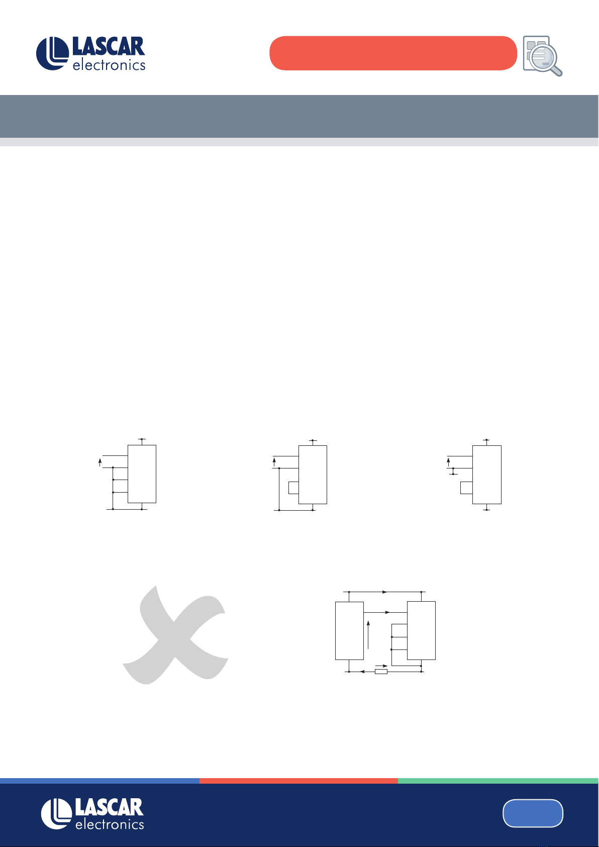
Using COM to generate signal ground Using TEST to generate signal ground Buffering the ground.
Many Lascar meters generate their own negative supplies internally.
All LED meters do and so do all S-type LCD meters. These supplies
may be used to power external circuitry. The maximum load depends
on the meter so consult the data sheet.
4.1.1 SPLIT SUPPLY OPERATION
4.1.2. GENERATING A GROUND LEVEL IN BATTERY POWERED EQUIPMENT
Fig. 4.2.a Fig. 4.2.b Fig. 4.2.c
4.1.3. SINGLE ENDED METER OPERATION
IN HI
IN LO
V+
V-
Input
V- (-5V)
V+
I Load
0V
POWER
IN
IN HI
IN LO
V-
V-
V+
V+
Input
IN HI IN HI IN HI
IN LO IN LO IN LO
V-
V- V- V-
V- V-
V+
V+ V+ V+
V+ V+
Input Input Input
COM TEST COM
(TEST)
3V 5V
-
+
Fig 4.1 Split supply operation
Fig.4.3 Using meter negative power output
www.lascarelectronics.com 8
Installation Operation - Section A&
4. INTERFACING WITH LINEAR AND DIGITAL CIRCUITRY
4.1 LINEAR
As mentioned in Sections 2 and 3, the most important aspect is to ensure that ground voltage levels do not cause problems. For the sake of simplicity,
we shall assume the linear circuit to be an op-amp. A number of linear systems can exist:-
i. Circuit operating from ± supplies, e.g.5-0-5V(LCD).
ii. Circuit operating from a single supply but needing a ground level to be generated in between, e.g. battery operated equipment (LCD).
iii. Circuit operating from a single supply with its output referenced to the negative (GND) supply (LED, S-type LCD).
If the signal to be measured is referred to ground, then IN LO will be connected to ground and IN HI to the signal. However, ensure that IN LO is
connected as close as possible to the ground connection point of the signal.
Advice on referring inputs to ground lines is given in Section 3. Be careful not to exceed the maximum supply voltage; the maximum supply voltage
quoted in data sheets is the maximum voltage between V+ and V-. If the maximum supply voltage is 15V, the maximum split supply is ±7.5V.
If the battery is formed with separate cells it is as well to have a centre-tap in the battery for the ground (0V). However, if you are using a packaged
battery such as the PP3, then other means are needed. The solution is to use either the COM or TEST (DGND) pins on the meter as the ground. The
choice depends on the circuit that must operate with the meter but there are a few considerations:
i. Using COM eliminates all common-mode voltages and because it is approximately 3V below V+, the ground will be well separated from either
supply rail even if the battery voltage drops down to 6V.
ii. TEST (DGND) may be a better choice if running off higher supplies such as 12V vehicle batteries.
iii. COM can sink but not source current. Any load on COM must not pull COM down towards the negative supply.
iv. TEST (DGND) can sink or source up to 1mA and is the ground for the internal meter logic.
v. If a load exceeding the conditions laid out in iii. and iv. above is likely, then the ground needs to be buffered.
Using COM to generate signal ground Using TEST to generate signal ground Buffering the ground.
Many Lascar meters generate their own negative supplies internally.
All LED meters do and so do all S-type LCD meters. These supplies
may be used to power external circuitry. The maximum load depends
on the meter so consult the data sheet.
4.1.1 SPLIT SUPPLY OPERATION
4.1.2. GENERATING A GROUND LEVEL IN BATTERY POWERED EQUIPMENT
Fig. 4.2.a Fig. 4.2.b Fig. 4.2.c
4.1.3. SINGLE ENDED METER OPERATION
IN HI
IN LO
V+
V-
Input
V- (-5V)
V+
I Load
0V
POWER
IN
IN HI
IN LO
V-
V-
V+
V+
Input
IN HI IN HI IN HI
IN LO IN LO IN LO
V-
V- V- V-
V- V-
V+
V+ V+ V+
V+ V+
Input Input Input
COM TEST COM
(TEST)
3V 5V
-
+
Fig 4.1 Split supply operation
Fig.4.3 Using meter negative power output
www.lascarelectronics.com 8
4. Interface With Linear and Digital Circuitry
4.1 Linear
As mentioned in Sections 2 and 3, the most important aspect is to ensure that ground voltage levels do not cause problems. For the sake of
simplicity, we shall assume the linear circuit to be an op-amp. A number of linear systems can exist:
Circuit operating from ± supplies, e.g. 5 - 0 - 5V (LCD).Circuit operating from a single supply but needing a ground level to be generated in between,
e.g. battery operated equipment (LCD). Circuit operating from a single supply with its output referenced to the negative (GND) supply (LED, S-type LCD).
4.1.2. Generating a Ground Level in Battery Powered Equipment
If the battery is formed with separate cells it is as well to have a centre-tap in the battery for the ground (0V). However, if you
are using a packaged battery such as the PP3, then other means are needed. The solution is to use either the COM or TEST
(DGND) pins on the meter as the ground. The choice depends on the circuit that must operate with the meter but there are a
few considerations:
i. Using COM eliminates all common-mode voltages and because it is approximately 3V below V+, the ground will be well
separated from either supply rail even if the battery voltage drops down to 6V.
ii. TEST (DGND) may be a better choice if running o higher supplies such as 12V vehicle batteries.
iii. COM can sink but not source current. Any load on COM must not pull COM down towards the negative supply.
iv. TEST (DGND) can sink or source up to 1mA and is the ground for the internal meter logic.
v. If a load exceeding the conditions laid out in iii. and iv. above is likely, then the ground needs to be buered.
4.1.1 Split Supply Operation
If the signal to be measured is referred to ground, then IN LO will be connected to ground and IN HI to the signal. However,
ensure that IN LO is connected as close as possible to the ground connection point of the signal.
Advice on referring inputs to ground lines is given in Section 3. Be careful not to exceed the maximum supply voltage; the
maximum supply voltage quoted in data sheets is the maximum voltage between V+ and V-. If the maximum supply voltage
is 15V, the maximum split supply is ±7.5V.