heinzinger ERS Compact Series User manual
www.heinzinger.com
Betriebsanleitung
User Manual
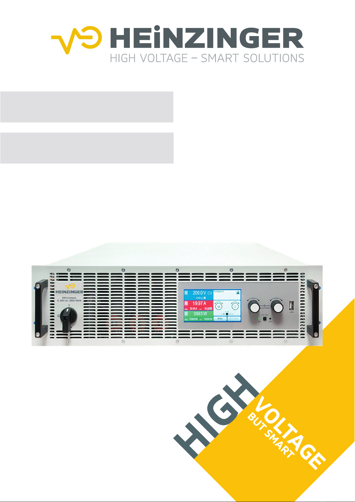
Bidirectional Power Supply System
Heinzinger ERS Compact-Series

TABLE OF CONTENTS
1. GENERAL
1.1 About this document......................................5
1.1.1 Retention and use..........................................5
1.1.2 Copyright........................................................5
1.1.3 Validity............................................................5
1.1.4 Symbols and warnings ..................................5
1.2 Warranty.........................................................5
1.3 Limitation of liability........................................5
1.4 Disposal of equipment...................................6
1.5 Product key....................................................6
1.6 Intended usage..............................................6
1.7 Safety.............................................................7
1.7.1 Safety notices.................................................7
1.7.2 Responsibility of the user...............................8
1.7.3 Responsibility of the operator .......................8
1.7.4 User requirements.........................................8
1.7.5 Alarm signals..................................................9
1.8 Technical Data ...............................................9
1.8.1 Approved operating conditions......................9
1.8.2 General technical data...................................9
1.8.3 Specictechnicaldata(380/400/480Vmod-
els)................................................................10
1.8.4 Specictechnicaldata(208Vmodels).......16
1.8.5 Views............................................................17
1.8.6 Controlelements(standardmodels)...........25
1.8.7 Controlelements(Slavemodels)................26
1.9 Construction and function............................27
1.9.1 General description......................................27
1.9.2 Block diagram..............................................27
1.9.3 Scope of delivery .........................................28
1.9.4 Accessories..................................................28
1.9.5 Options.........................................................29
1.9.6 Thecontrolpanel(HMI,standardmodels) .29
1.9.7 Thecontrolpanel(Slavemodels) ...............32
1.9.8 USBport(rearside).....................................33
1.9.9 Interfacemoduleslot(standardmodels).....33
1.9.10 Analoginterface(standardmodels) ............34
1.9.11 “Share BUS” connector ...............................34
1.9.12 “Sense”connector(remotesensing)...........34
1.9.13 Master-Slavebus.........................................34
1.9.14 Ethernetport(standardmodels) .................35
1.9.15 Water cooling...............................................35
2. INSTALLATION &
COMMISSIONING
2.1 Transport and storage .................................36
2.1.1 Transport......................................................36
2.1.2 Packaging ....................................................36
2.1.3 Storage.........................................................36
2.2 Unpacking and visual check........................36
2.3 Installation....................................................36
2.3.1 Safety procedures before installation and
use................................................................36
2.3.2 Preparation...................................................36
2.3.3 Installing the device .....................................39
2.3.4 Connectiontowatersupply(WCmodels) ..40
2.3.5 Connection toAC supply.............................42
2.3.6 Connection to DC loads or DC sources......45
2.3.7 Connection of remote sensing ....................46
2.3.8 Grounding of the DC terminal......................47
2.3.9 Installation of an interface module...............47
2.3.10 Connectionoftheanaloginterface .............47
2.3.11 Connection of the Share bus.......................48
2.3.12 ConnectionoftheUSBport(rearside).......48
2.3.13 Initial commission.........................................48
2.3.14 Commissionafterarmwareupdateora
long period of non-use.................................48
3. OPERATIONANDAPPLICATION
3.1 Terms............................................................49
3.2 Important notes............................................49
3.2.1 Personal safety............................................49
3.2.2 General.........................................................49
3.3 Operating modes.........................................49
3.3.1 Voltageregulation/Constantvoltage .........49
3.3.2 Currentregulation/constantcurrent/current
limiting ..........................................................50
3.3.3 Powerregulation/constantpower/power
limiting ..........................................................50
3.3.4 Internalresistanceregulation(source
mode)...........................................................51
3.3.5 Resistanceregulation/constantresistance
(sinkmode) ..................................................51
3.3.6 Sink-source mode switching........................52
3.3.7 Dynamic characteristics and stability crite-
ria..................................................................52
3.4 Alarm conditions ..........................................53
3.4.1 Power Fail ...................................................53
3.4.2 Overtemperature..........................................53
3.4.3 Overvoltage protection.................................53
3.4.4 Overcurrent protection.................................53
3.4.5 Overpower protection..................................53
3.4.6 Safety OVP ..................................................54
3.4.7 Share bus fail...............................................54
3.5 Manualoperation .........................................55
3.5.1 Switching on the device...............................55
3.5.2 Switchingthedeviceo...............................55
3.5.3 Congurationviathemenu .........................55
3.5.4 Adjustment limits..........................................63
3.5.5 Changing the operating mode.....................63
3.5.6 Manualadjustmentofsetvalues(standard
models).........................................................64
3.5.7 SwitchingtheDCterminalonoro.............65
3.5.8 RecordingtoUSBstick(logging,standard
models).........................................................65

3.5.9 The quick menu...........................................66
3.5.10 Thegraph.....................................................67
3.6 Remote control.............................................68
3.6.1 General.........................................................68
3.6.2 Control locations..........................................68
3.6.3 Remote control via a digital interface..........68
3.6.4 Remote control via the analog interface .....71
3.7 Alarms and monitoring.................................76
3.7.1 Denitionofterms........................................76
3.7.2 Device alarm and event handling................76
3.8 Lockingthecontrolpanel(HMI) ..................79
3.9 Lockingthe“Limits”and“Proles”...............79
3.10 Loadingandsavinguserproles ................80
3.11 The function generator.................................81
3.11.1 Introduction...................................................81
3.11.2 General.........................................................81
3.11.3 Methodofoperation.....................................82
3.11.4 Manualoperation .........................................83
3.11.5 Sine wave function.......................................84
3.11.6 Triangular function .......................................84
3.11.7 Rectangular function....................................85
3.11.8 Trapezoidal function.....................................86
3.11.9 DIN40839function ......................................86
3.11.10 Arbitraryfunction..........................................87
3.11.11 Ramp function..............................................91
3.11.12 IUtablefunction(XYtable)..........................92
3.11.13 SimplePV(photovoltaics)function .............93
3.11.14 FCtablefunction(fuelcell)..........................95
3.11.15 Extended PV function according to EN
50530 ...........................................................96
3.11.16 Battery test function...................................102
3.11.17 MPPtrackingfunction................................105
3.11.18 Remote control of the function generator..107
3.12 Other applications......................................108
3.12.1 Paralleloperationinmaster-slave(MS)....108
3.12.2 Series connection......................................111
4. SERVICEAND MAINTENANCE
4.1 Maintenance/cleaning..............................112
4.1.1 Battery replacement...................................112
4.2 Faultnding/diagnosis/repair.................112
4.2.1 Firmware updates......................................112
4.3 Calibration..................................................113
4.3.1 Preface.......................................................113
4.3.2 Preparation.................................................113
4.3.3 Calibration procedure ................................113
5. CONTACTAND SUPPORT
5.1 General.......................................................114
5.2 Contact options..........................................114

Heinzinger electronic GmbH Phone: +49 (0) 8031 2458 0 www.heinzinger.com
Anton-Jakob-Str. 4, 83026 Rosenheim Fax: + 49 (0) 8031 2458 58 info@heinzinger.de
Germany
Page 4
ERS COMPACT
Heinzinger electronic GmbH Phone: +49 (0) 8031 2458 0 www.heinzinger.com
Anton-Jakob-Str. 4, 83026 Rosenheim Fax: + 49 (0) 8031 2458 58 info@heinzinger.de
Germany
Page 5
ERS COMPACT
1. General
1.1 About this document
1.1.1 Retention and use
This document is to be kept in the vicinity of the equipment for future reference and explanation of the operation of
thedevice.Thisdocumentistobedeliveredandkeptwiththeequipmentincaseofchangeoflocationand/oruser.
1.1.2 Copyright
Reprinting,copying,alsopartially,usageforotherpurposesasforeseenofthismanualareforbiddenandbreach
may lead to legal process.
1.1.3 Validity
This manual is valid for the following equipment and its variants:
Model Model Model
ERSC60-1000/30 ERSC360-360/30 ERSC1000-80/30
ERSC80-1000/30 ERSC500-180/30 ERSC1500-60/30
ERSC200-420/30 ERSC750-120/30 ERSC1000-60/30
1.1.4 Symbols and warnings
Warning andsafety notices aswell as generalnotices in thisdocumentare shown ina box witha symbol asfollows:
Symbol for a life threatening danger
Symbolforgeneralsafetynotices(instructionsanddamageprotectionbans)orimportantinfor-
mation for operation
Symbol for general notices
1.2 Warranty
Heinzinger guarantees the functional competence of the applied technology and the stated performance param-
eters. The warranty period begins with the delivery of free from defects equipment.
Termsofguaranteeareincludedinthegeneraltermsandconditions(TOS)ofHeinzinger.
1.3 Limitation of liability
Allstatementsandinstructionsinthismanualarebasedoncurrentnormsandregulations,up-to-datetechnology
and our long term knowledge and experience. The manufacturer accepts no liability for losses due to:
• Usage for purposes other than designed
• Use by untrained personnel
• Rebuilding by the customer
• Technical changes
• Use of not authorized spare parts
Theactualdelivereddevice(s)maydierfromtheexplanationsanddiagramsgivenhereduetolatesttechnical
changes or due to customized models with the inclusion of additionally ordered options.

Heinzinger electronic GmbH Phone: +49 (0) 8031 2458 0 www.heinzinger.com
Anton-Jakob-Str. 4, 83026 Rosenheim Fax: + 49 (0) 8031 2458 58 info@heinzinger.de
Germany
Page 6
ERS COMPACT
1.4 Disposal of equipment
Apieceofequipmentwhichisintendedfordisposalmust,accordingtoEuropeanlawsandregulations(ElektroG,
WEEE)bereturnedtothemanufacturerforscrapping,unlessthepersonoperatingthepieceofequipmentoran-
other,delegatedpersonisconductingthedisposal.Ourequipmentfallsundertheseregulationsandisaccordingly
marked with the following symbol:
The device contains a Lithium battery cell. Disposal of that battery follows the above stated rule
orspeciclocalregulations.
1.5 Product key
Not abailable
1.6 Intended usage
Theequipment isintended tobe usedonly asa variablevoltage andcurrent sourceor onlyas avariablecurrent sink.
TypicalapplicationforavoltagesourceisDCpowersupplytoanyrelevantuser,includingwhenusedasbattery
chargertotestchargevariousbatterytypes,andforcurrentsinksthereplacementofanohmicresistorbyan
adjustable electronic DC load in order to load relevant voltage and current sources of any type.
AdditionallytothefunctionalityoftheequipmentassourceorsinkofelectricalenergyontheDCside,allmodelsin
thisseriesarealsoso-calledrecuperatingdevicesandthusnotjustdrainenergyontheACside,butalsosource
energy when being sinks on the DC side. This is where the term “bidirectional” comes from. In sink mode the de-
vicesbecomeenergyrecoverers,butarenotdenedorconsideredasenergygenerationequipment.
• Claims of any sort due to damage caused by non-intended usage will not be accepted
• All damage caused by non-intended usage is solely the responsibility of the operator

Heinzinger electronic GmbH Phone: +49 (0) 8031 2458 0 www.heinzinger.com
Anton-Jakob-Str. 4, 83026 Rosenheim Fax: + 49 (0) 8031 2458 58 info@heinzinger.de
Germany
Page 7
ERS COMPACT
1.7 Safety
1.7.1 Safety notices
Mortal danger - Hazardous voltage
• Electrical equipment operation means that some parts can be under dangerous voltage.
Therefore all parts under voltage must be covered! This basically applies to all models,
though 60 V models according to SELV can’t generate hazardous DC voltage.
• Never touch cables or connectors directly after unplugging from mains supply as the
danger of electric shock remains!
• Never touch the contacts on DC terminal directly after switching the device o, because
when running in source mode there still can be dangerous voltage present, sinking more
or less slowly depending on the load!
• There can be dangerous potential between DC minus to PE or DC plus to PE due to
charged X capacitors, even when the DC output/input is not switched on and the device is
still running. Never touch PE and any of the DC poles at the same time with bare hands!
• Always follow 5 safety rules when working with electric devices:
• Disconnect completely
• Secure against reconnection
• Verify that the system is dead
• Carry out earthing and short-circuiting
• Provide protection from adjacent live parts
• In situations where the device works in source mode, with a voltage > 0 adjusted and
the DC output being on, the output voltage can remain at the last setting after switching
the DC output o again, in case the set value of current for the internal load (sink mode)
is set to 0
• Even with the DC terminal being switched o, the device can generate a small, not load-
able voltage (< 2 V) on this terminal!
• The equipment must only be used as intended
• Theequipment is onlyapprovedfor use withinthe connection limitsstated on the productlabel.
• Donotinsertanyobject,particularlymetallic,throughtheventilatorslots
• Avoidanyuseofliquidsneartheequipment.Protectthedevicefromwet,dampandconden-
sation.
• Whenoperatingthedeviceaspowersupply:donotconnectloads,particularlysuchwithlow
resistance,tothedevicewhiletheDCoutputisswitchedon;sparkingmayoccurwhichcan
cause burns as well as damage to the equipment and to the load.
• Whenoperating thedeviceas electronicload: do notconnect powersources to thedevice while
theDCinputisswitchedon;sparkingmayoccurwhichcancauseburnsaswellasdamageto
the equipment and to the source.
• ESDregulations must beapplied whenplugginginterface cardsor modules intothe relative slot
• Interfacecardsormodulesmayonlybeattachedorremovedafterthedeviceisswitchedo.
It’s not necessary to open the device.
• Donot connectexternal powersources withreversed polarityto theDC terminal!Theequipment
willbedamaged,evenwhencompletelypoweredo.
• Never connect external power sources to the DC terminal that can generate a higher voltage
than the rated voltage of the device!
• Never insert a network cable which is connected to Ethernet or its components into the mas-
ter-slave sockets on the rear side of the device!
• Alwayscongurethevariousprotectingfeaturesagainstovercurrent,overpoweretc.forsen-
sitive loads to what the target application requires!
• When operating the device as electronic load: always make sure that the energy recovery can
feed back the inverted energy and that it does not switch to isolated operation. For situations
ofisolatedoperationasupervisiondevice(AIU,gridandplatprotection)hastobeinstalled
• It’s not allowed to run the device onAC sources such as generators or UPS equipment. It must
only be connected to a power grid!
Heinzinger electronic GmbH Phone: +49 (0) 8031 2458 0 www.heinzinger.com
Anton-Jakob-Str. 4, 83026 Rosenheim Fax: + 49 (0) 8031 2458 58 info@heinzinger.de
Germany
Page 8
ERS COMPACT
1.7.2 Responsibility of the user
The equipment is in industrial operation. Therefore the operators are governed by the legal safety regulations.
Alongsidethewarningandsafetynoticesinthismanualtherelevantsafety,accidentpreventionandenvironmental
regulations must also be applied. In particular the users of the equipment:
• must be informed of the relevant job safety requirements
• mustworktothedenedresponsibilitiesforoperation,maintenanceandcleaningoftheequipment
• before starting work must have read and understood the operating manual
• must use the designated and recommended safety equipment.
Furthermore,anyoneworkingwiththeequipmentisresponsibleforensuringthatthedeviceisatalltimestech-
nicallytforuse.
1.7.3 Responsibility of the operator
Operatorisanynaturalorlegalpersonwhousestheequipmentordelegatestheusagetoathirdparty,andis
responsibleduringitsusageforthesafetyoftheuser,otherpersonnelorthirdparties.
The equipment is in industrial operation. Therefore the operators are governed by the legal safety regulations.
Alongsidethewarningandsafetynoticesinthismanualtherelevantsafety,accidentpreventionandenvironmental
regulations must also be applied. In particular the operator has to
• be acquainted with the relevant job safety requirements
• identifyotherpossibledangersarisingfromthespecicusageconditionsattheworkstationviaariskassessment
• introduce the necessary steps in the operating procedures for the local conditions
• regularly control that the operating procedures are current
• updatetheoperatingprocedureswherenecessarytoreectchangesinregulation,standardsoroperatingcon-
ditions.
• deneclearlyandunambiguouslytheresponsibilitiesforoperation,maintenanceandcleaningoftheequipment.
• ensure that all employees who use the equipment have read and understood the manual. Furthermore the users
are to be regularly schooled in working with the equipment and the possible dangers.
• provide all personnel who work with the equipment with the designated and recommended safety equipment
Furthermore,theoperatorisresponsibleforensuringthatthedeviceisatalltimestechnicallytforuse.
1.7.4 User requirements
Any activity with equipment of this type may only be performed by persons who are able to work correctly and
reliably and satisfy the requirements of the job.
• Personswhosereactioncapabilityisnegativelyinuencedbye.g.drugs,alcoholormedicationmaynotoperate
the equipment.
• Age or job related regulations valid at the operating site must always be applied.
Danger for unqualied users
Improper operation can cause person or object damage. Only persons who have the nec-
essary training, knowledge and experience may use the equipment.
Delegated persons are those who have been properly and demonstrably instructed in their tasks and the atten-
dant dangers.
Qualied personsarethosewhoareablethroughtraining,knowledgeandexperienceaswellasknowledgeof
thespecicdetailstocarryoutalltherequiredtasks,identifydangersandavoidpersonalandotherrisks.
Allworkonelectricalequipmentmayonlybeperformedbyqualiedelectricians.

Heinzinger electronic GmbH Phone: +49 (0) 8031 2458 0 www.heinzinger.com
Anton-Jakob-Str. 4, 83026 Rosenheim Fax: + 49 (0) 8031 2458 58 info@heinzinger.de
Germany
Page 9
ERS COMPACT
1.7.5 Alarm signals
Theequipmentoersvariouspossibilitiesforsignalingalarmconditions,however,notfordangersituations.The
signalsmaybeoptical(onthedisplayastextorviaLED),acoustic(piezobuzzer)orelectronic(pin/statusoutput
ofananaloginterface).AllalarmswillcausethedevicetoswitchotheDCterminal.
The meaning of the signals is as follows:
Signal OT
(OverTemperature)
• Overheating of the device
• DCterminalwillbeswitchedo
• Non-critical
Signal OVP / SOVP
(OverVoltage)
• Overvoltage shutdown of the DC terminal due to high voltage entering the device or
generated by the device itself due to a defect
• Critical!Thedeviceand/ortheloadcouldbedamaged
Signal OCP
(OverCurrent)
• Shutdown of the DC terminal due to excess of the preset limit
• Non-critical,protectstheloadorsourcefromexcessivecurrentconsumption
Signal OPP
(OverPower)
• Shutdown of the DC terminal due to excess of the preset limit
• Non-critical,protectstheloadorsourcefromexcessivepowerconsumption
Signal PF
(PowerFail)
• DC terminal shutdown due to AC undervoltage or defect in the AC section
• Critical on overvoltage! AC section could be damaged
Signal MSP
(Master-SlavePro-
tection)
• DC terminal shutdown due to communication problems on the master-slave bus
• Non-critical
Signal SF
(ShareBusFail)
• DC terminal shutdown due to signal distortion on the Share bus
• Non-critical
1.8 Technical Data
1.8.1 Approved operating conditions
• Use only inside dry buildings
• Ambienttemperature0-50°C(32-122°F)
• Operationalaltitude:max.2000m(1.242mi)abovesealevel
• Max80%relativehumidity,notcondensing
1.8.2 General technical data
Display(standard): ColorTFTtouchscreenwithgorillaglass,5”,800ptx480pt,capacitive
Display(Slave): 6LEDs
Controls(standard): 2rotaryknobswithpushbuttonfunction,1pushbutton
Controls(Slave): 1pushbutton
The rated values for the device determine the maximum adjustable ranges.
1.8.2.1 Terms
Inconnectionwiththemodelofanyofthedevicesmentionedbelow,theword“standard” or “standard model”
referstothebasicversionwithdisplay,whichalsoappliestotheversionswithwatercoolingorUS208Voption,
astheydon’tchangethemanualhandlingontheHMI.

Heinzinger electronic GmbH Phone: +49 (0) 8031 2458 0 www.heinzinger.com
Anton-Jakob-Str. 4, 83026 Rosenheim Fax: + 49 (0) 8031 2458 58 info@heinzinger.de
Germany
Page 10
ERS COMPACT
1.8.3 Specic technical data (380/400/480 V models)
(1Relatedtothenominalvalues,theaccuracydenesthemaximumdeviationbetweenanadjustedvaluesandthetrue(actual)value.
Example:a1000Amodelhasmin.0.2%currentaccuracy,thatis2A.Whenadjustingthecurrentto300A,theactualcurrentontheDCterminalisallowedto
diermax.2Afromthesetvalue,whichmeansitcouldbebetween298Aand302A.
(2RMSvalue:LF0...300kHz,PPvalue:HF0...20MHz
(3ThedisplayerroraddstotheerroroftherelatedactualvalueontheDCterminal
30 kW Model 380/400/480 V
ERSC 60-1000/30 ERSC 80-1000/30 ERSC 200-420/30
AC supply
Voltagerange(L-L) 380/400/480V,±10%
Frequency 45-66Hz
Connection 3ph,PE
Leak current ≤10mA
Phasecurrent/Inrushcurrent < 56 A
Eciencyofenergyrecovery ≤94% ≤94% ≤94.2%
Power factor ≈0.99
Power consumption at no load At400VAC:ca.120W(true)plusca.1200VA(apparent)
DC terminal
Max.voltageUMax 60V 80V 200V
Max.currentIMax 1000A 1000A 420A
Max.powerPMax 30000W 30000W 30000W
Overvoltage protection range 0...66V 0...88V 0...220V
Overcurrent protection range 0...1100A 0...1100A 0...462A
Overpower protection range 0…33000W 0…33000W 0…33000W
Temperaturecoecient(Δ/K) Voltagesetvalues/currentsetvalues:100ppm
Capacitance(approx.) 25380μF 25380μF 5400μF
Voltage regulation (general)
Adjustment range 0...61.2V 0...81.6V 0...204V
Accuracy (1(at23±5°C/73±9°F) ≤0.05%UNom ≤0.05%UNom ≤0.05%UNom
Lineregulationat±10%ΔUAC ≤0.02%UNom ≤0.02%UNom ≤0.02%UNom
Display: Resolution See section “1.9.6.4. Resolution of the displayed values”
Display: Accuracy (3 ≤0.2%UNom ≤0.2%UNom ≤0.2%UNom
Remote sensing compensation Max.5%UNom Max.5%UNom Max.5%UNom
Voltage regulation (power supply)
Loadregulationat0...100%ΔIOUT ≤0.05%UNom ≤0.05%UNom ≤0.05%UNom
Risetime10...90%ΔUOUT Max.30ms Max.30ms Max.30ms
TransienttimeafterΔIOUT ≤1.5ms ≤1.5ms ≤1.5ms
Ripple (2 ≤320mVPP
≤25mVRMS
≤320mVPP
≤25mVRMS
≤300mVPP
≤40mVRMS
Fall time at no load after switching
DCterminalo -Downfrom100%to<60V:lessthan10s
Voltage regulation (el. load)
Loadregulationat0...100%ΔU ≤0.05%UNom ≤0.05%UNom ≤0.05%UNom
Current regulation (general)
Adjustment range 0...1020A 0...1020A 0...428.4A
Accuracy (1(at23±5°C/73±9°F) ≤0.1%INom ≤0.1%INom ≤0.1%INom
Lineregulationat±10%ΔUAC ≤0.05%INom ≤0.05%INom ≤0.05%INom
Display: Resolution See section “1.9.6.4. Resolution of the displayed values”
Display: Accuracy (3 ≤0.2%INom ≤0.2%INom ≤0.2%INom
Current regulation (power supply)
Loadregulationat0...100%ΔUOUT ≤0.15%INom ≤0.15%INom ≤0.15%INom
Current regulation (el. load)
Loadregulationat0...100%ΔUIN ≤0.15%INom ≤0.15%INom ≤0.15%INom
Ripple (2 ≤240mARMS ≤240mARMS ≤66mARMS

Heinzinger electronic GmbH Phone: +49 (0) 8031 2458 0 www.heinzinger.com
Anton-Jakob-Str. 4, 83026 Rosenheim Fax: + 49 (0) 8031 2458 58 info@heinzinger.de
Germany
Page 11
ERS COMPACT
30 kW Model 380/400/480 V
ERSC 60-1000/30 ERSC 80-1000/30 ERSC 200-420/30
Power regulation
Adjustment range 0…30600W 0…30600W 0…30600W
Accuracy (1(at23±5°C/73±9°F) ≤0.3%PNom ≤0.3%PNom ≤0.3%PNom
Lineregulationat±10%ΔUAC ≤0.05%PNom ≤0.05%PNom ≤0.05%PNom
Loadreg.at10-90%ΔUDC*ΔIDC ≤0.75%PNom ≤0.75%PNom ≤0.75%PNom
Display: Resolution See section “1.9.6.4. Resolution of the displayed values”
Display: Accuracy (2 ≤0.2%PNom ≤0.2%PNom ≤0.2%PNom
Eciency(4 ≤94% ≤94% ≤94.2%
Resistance regulation
Adjustment range 0.003...5Ω 0.003...5Ω 0.0165...25Ω
Accuracy (1(at23±5°C/73±9°F) ≤0.3%ofmax.resistance±0.1%ofmaximumcurrent
Display: Resolution See section “1.9.6.4. Resolution of the displayed values”
Analog interface (3
Signals See “3.6.4.5. Analog interface specication”
Galvanic isolation to the device Max.725VDC
Insulation Max.allowedpotentialshift(oatingvoltage)ontheDCterminal:
Negative DC to PE ±500VDC ±500VDC ±725VDC
Positive DC to PE +600VDC +600VDC +1000VDC
AC input <-> PE 2.5 kV DC
Miscellaneous
Cooling(Standard/Slave) Temperaturecontrolledfans,frontinlet,rearexhaust
Cooling(WC) Water(IP20)
Ambient temperature 0...50°C(32...133°F)
Storage temperature -20...70°C(-4...158°F)
Humidity ≤80%,notcondensing
Standards EN61010-1:2007-11,EN50160:2011-02
EN61000-6-2:2016-05,EN61000-6-3:2011-09
Overvoltage category 2
Protection class 1
Pollution degree 2
Operational altitude ≤2000m(6562ft)
Digital interfaces
Featured(Standard) 1xUSBand1xEthernetforcommunication,1xUSB-Afordatarecording,Master-slave
Slot(Standard) Optional:CANopen,Probus,Pronet,RS232,CAN,EtherCAT,ModBusTCP
Galvanic isolation from device Max.725VDC
Terminals
Rear side ShareBus,DCterminal,ACsupply,remotesensing,analoginterface,USB,Ethernet
master-slavebus,interfacemoduleslot
Front side USB for sticks
Dimensions
Enclosure(WxHxD) 19“x4Ux670mm(26.4”)
Total(WxHxD) 483x177xmin.760mm(19”x7”xmin.29.9”)
Weight (Standard / Slave) ≈50kg(110lbs) ≈50kg(110lbs) ≈50kg(110lbs)
Weight (WC) ≈56kg(123lbs) ≈56kg(123lbs) ≈56kg(123lbs)
(1Relatedtothenominalvalues,theaccuracydenesthemaximumdeviationbetweenanadjustedvaluesandthetrue(actual)value.Withtheresistance,the
accuracy rating already includes the error of the actual resistance display.
(2ThedisplayerroraddstotheerroroftherelatedactualvalueontheDCterminal
(3Fortechnicalspecicationsoftheanaloginterfacesee“3.6.4.5 Analog interface specication” on page 72
(4Typicalvalueat100%voltageand100%power
(5WC=withoptionalwater-cooling

Heinzinger electronic GmbH Phone: +49 (0) 8031 2458 0 www.heinzinger.com
Anton-Jakob-Str. 4, 83026 Rosenheim Fax: + 49 (0) 8031 2458 58 info@heinzinger.de
Germany
Page 12
ERS COMPACT
30 kW Model 380/400/480 V
ERSC 360-240/30 ERSC 500-180/30 ERSC 750-120/30
AC supply
Voltagerange(L-L) 380/400/480V,±10%
Frequency 45-66Hz
Connection 3ph,PE
Leak current ≤10mA
Phasecurrent/Inrushcurrent < 56 A
Eciencyofenergyrecovery ≤94.6% ≤95.3% ≤95.5%
Power factor ≈0.99
Power consumption at no load At400VAC:ca.120W(true)plusca.1200VA(apparent)
DC terminal
Max.voltageUMax 360V 500V 750V
Max.currentIMax 240A 180A 120A
Max.powerPMax 30000W 30000W 30000W
Overvoltage protection range 0...396V 0...550V 0...825V
Overcurrent protection range 0...264A 0...198A 0...132A
Overpower protection range 0…33000W 0…33000W 0…33000W
Temperaturecoecient(Δ/K) Voltagesetvalues/currentsetvalues:100ppm
Capacitance(approx.) 1800μF 675μF 450μF
Voltage regulation (general)
Adjustment range 0...376.2V 0...510V 0...765V
Accuracy (1(at23±5°C/73±9°F) ≤0.05%UNom ≤0.05%UNom ≤0.05%UNom
Lineregulationat±10%ΔUAC ≤0.02%UNom ≤0.02%UNom ≤0.02%UNom
Display: Resolution See section “1.9.6.4. Resolution of the displayed values”
Display: Accuracy (3 ≤0.2%UNom ≤0.2%UNom ≤0.2%UNom
Remote sensing compensation Max.5%UNom Max.5%UNom Max.5%UNom
Voltage regulation (power supply)
Loadregulationat0...100%ΔIOUT ≤0.05%UNom ≤0.05%UNom ≤0.05%UNom
Risetime10...90%ΔUOUT Max.30ms Max.30ms Max.30ms
TransienttimeafterΔIOUT ≤1.5ms ≤1.5ms ≤1.5ms
Ripple (2 ≤320mVPP
≤55mVRMS
≤350mVPP
≤70mVRMS
≤800mVPP
≤200mVRMS
Fall time at no load after switching
DCterminalo Downfrom100%to<60V:lessthan10s
Voltage regulation (el. load)
Loadregulationat0...100%ΔU ≤0.05%UNom ≤0.05%UNom ≤0.05%UNom
Current regulation (general)
Adjustment range 0...244.8A 0...183.6A 0...122.4A
Accuracy (1(at23±5°C/73±9°F) ≤0.1%INom ≤0.1%INom ≤0.1%INom
Lineregulationat±10%ΔUAC ≤0.05%INom ≤0.05%INom ≤0.05%INom
Display: Resolution See section “1.9.6.4. Resolution of the displayed values”
Display: Accuracy (3 ≤0.2%INom ≤0.2%INom ≤0.2%INom
Current regulation (power supply)
Loadregulationat0...100%ΔUOUT ≤0.15%INom ≤0.15%INom ≤0.15%INom
Current regulation (el. load)
Loadregulationat0...100%ΔUIN ≤0.15%INom ≤0.15%INom ≤0.15%INom
Ripple (2 ≤50mARMS ≤48mARMS ≤48mARMS
(1Relatedtothenominalvalues,theaccuracydenesthemaximumdeviationbetweenanadjustedvaluesandthetrue(actual)value.
Example:a1000Amodelhasmin.0.2%currentaccuracy,thatis2A.Whenadjustingthecurrentto300A,theactualcurrentontheDCterminalisallowedto
diermax.2Afromthesetvalue,whichmeansitcouldbebetween298Aand302A.
(2RMSvalue:LF0...300kHz,PPvalue:HF0...20MHz
(3ThedisplayerroraddstotheerroroftherelatedactualvalueontheDCterminal

Heinzinger electronic GmbH Phone: +49 (0) 8031 2458 0 www.heinzinger.com
Anton-Jakob-Str. 4, 83026 Rosenheim Fax: + 49 (0) 8031 2458 58 info@heinzinger.de
Germany
Page 13
ERS COMPACT
30 kW Model 380/400/480 V
ERSC 360-240/30 ERSC 500-180/30 ERSC 750-120/30
Power regulation
Adjustment range 0…30600W 0…30600W 0…30600W
Accuracy (1(at23±5°C/73±9°F) ≤0.3%PNom ≤0.3%PNom ≤0.3%PNom
Lineregulationat±10%ΔUAC ≤0.05%PNom ≤0.05%PNom ≤0.05%PNom
Loadreg.at10-90%ΔUDC*ΔIDC ≤0.75%PNom ≤0.75%PNom ≤0.75%PNom
Display: Resolution See section “1.9.6.4. Resolution of the displayed values”
Display: Accuracy (2 ≤0.2%PNom ≤0.2%PNom ≤0.2%PNom
Eciency(4 ≤94.6% ≤95.3% ≤95.5%
Resistance regulation
Adjustment range 0.05...90Ω 0.08...170Ω 0.2...370Ω
Accuracy (1(at23±5°C/73±9°F) ≤0.3%ofmax.resistance±0.1%ofmaximumcurrent
Display: Resolution See section “1.9.6.4. Resolution of the displayed values”
Analog interface (3
Signals See “3.6.4.5. Analog interface specication”
Galvanic isolation to the device Max.1500VDC
Insulation Max.allowedpotentialshift(oatingvoltage)ontheDCterminal:
Negative DC to PE ±1500VDC ±1500VDC ±1500VDC
Positive DC to PE +2000VDC +2000VDC +2000VDC
AC input <-> PE 2.5 kV DC
Miscellaneous
Cooling(Standard/Slave) Temperaturecontrolledfans,frontinlet,rearexhaust
Cooling(WC) Water(IP20)
Ambient temperature 0...50°C(32...133°F)
Storage temperature -20...70°C(-4...158°F)
Humidity ≤80%,notcondensing
Standards EN61010-1:2007-11,EN50160:2011-02
EN61000-6-2:2016-05,EN61000-6-3:2011-09
Overvoltage category 2
Protection class 1
Pollution degree 2
Operational altitude ≤2000m(6562ft)
Digital interfaces
Featured(Standard) 1xUSBand1xEthernetforcommunication,1xUSB-Afordatarecording,Master-slave
Slot(Standard) Optional:CANopen,Probus,Pronet,RS232,CAN,EtherCAT,ModBusTCP
Galvanic isolation from device Max.1500VDC
Terminals
Rear side ShareBus,DCterminal,ACsupply,remotesensing,analoginterface,USB,Ethernet
master-slavebus,interfacemoduleslot
Front side USB for sticks
Dimensions
Enclosure(WxHxD) 19“x4Ux670mm(26.4”)
Total(WxHxD) 483x177xmin.760mm(19”x7”xmin.29.9”)
Weight (Standard / Slave) ≈50kg(110lbs) ≈50kg(110lbs) ≈50kg(110lbs)
Weight (WC) ≈56kg(123lbs) ≈56kg(123lbs) ≈56kg(123lbs)
(1Relatedtothenominalvalues,theaccuracydenesthemaximumdeviationbetweenanadjustedvaluesandthetrue(actual)value.Withtheresistance,the
accuracy rating already includes the error of the actual resistance display.
(2ThedisplayerroraddstotheerroroftherelatedactualvalueontheDCterminal
(3Fortechnicalspecicationsoftheanaloginterfacesee“3.6.4.5 Analog interface specication” on page 72
(4Typicalvalueat100%voltageand100%power
(5WC=withoptionalwater-cooling

Heinzinger electronic GmbH Phone: +49 (0) 8031 2458 0 www.heinzinger.com
Anton-Jakob-Str. 4, 83026 Rosenheim Fax: + 49 (0) 8031 2458 58 info@heinzinger.de
Germany
Page 14
ERS COMPACT
30 kW Model 380/400/480 V
ERSC 1000-80/30 ERSC 1500-60/30 ERSC 1000-60/30
AC supply
Voltagerange(L-L) 380/400/480V,±10%
Frequency 45-66Hz
Connection 3ph,PE
Leak current ≤10mA
Phasecurrent/Inrushcurrent < 56 A
Eciencyofenergyrecovery ≤94.6% ≤95.3% ≤95.5%
Power factor ≈0.99
Power consumption at no load At400VAC:ca.120W(true)plusca.1200VA(apparent)
DC terminal
Max.voltageUMax 1000V 1500V 2000V
Max.currentIMax 80A 60A 40A
Max.powerPMax 30000W 30000W 30000W
Overvoltage protection range 0...1100V 0...1650V 0...2200V
Overcurrent protection range 0...88A 0...66A 0...44A
Overpower protection range 0…33000W 0…33000W 0…33000W
Temperaturecoecient(Δ/K) Voltagesetvalues/currentsetvalues:100ppm
Capacitance(approx.) 200μF 75μF 50μF
Voltage regulation (general)
Adjustment range 0...1020V 0...1530V 0...2040V
Accuracy (1(at23±5°C/73±9°F) ≤0.05%UNom ≤0.05%UNom ≤0.05%UNom
Lineregulationat±10%ΔUAC ≤0.02%UNom ≤0.02%UNom ≤0.02%UNom
Display: Resolution See section “1.9.6.4. Resolution of the displayed values”
Display: Accuracy (3 ≤0.2%UNom ≤0.2%UNom ≤0.2%UNom
Remote sensing compensation Max.5%UNom Max.5%UNom Max.5%UNom
Voltage regulation (power supply)
Loadregulationat0...100%ΔIOUT ≤0.05%UNom ≤0.05%UNom ≤0.05%UNom
Risetime10...90%ΔUOUT Max.30ms Max.30ms Max.30ms
TransienttimeafterΔIOUT ≤1.5ms ≤1.5ms ≤1.5ms
Ripple (2 ≤1600mVPP
≤300mVRMS
≤2400mVPP
≤400mVRMS
≤2400mVPP
≤400mVRMS
Fall time at no load after switching
DCterminalo Downfrom100%to<60V:lessthan10s
Voltage regulation (el. load)
Loadregulationat0...100%ΔU ≤0.05%UNom ≤0.05%UNom ≤0.05%UNom
Current regulation (general)
Adjustment range 0...81.6A 0...61.2A 0...40.8A
Accuracy (1(at23±5°C/73±9°F) ≤0.1%INom ≤0.1%INom ≤0.1%INom
Lineregulationat±10%ΔUAC ≤0.05%INom ≤0.05%INom ≤0.05%INom
Display: Resolution See section “1.9.6.4. Resolution of the displayed values”
Display: Accuracy (3 ≤0.2%INom ≤0.2%INom ≤0.2%INom
Current regulation (power supply)
Loadregulationat0...100%ΔUOUT ≤0.15%INom ≤0.15%INom ≤0.15%INom
Current regulation (el. load)
Loadregulationat0...100%ΔUIN ≤0.15%INom ≤0.15%INom ≤0.15%INom
Ripple (2 ≤16mARMS ≤26mARMS ≤26mARMS
(1Relatedtothenominalvalues,theaccuracydenesthemaximumdeviationbetweenanadjustedvaluesandthetrue(actual)value.
Example:a1000Amodelhasmin.0.2%currentaccuracy,thatis2A.Whenadjustingthecurrentto300A,theactualcurrentontheDCterminalisallowedto
diermax.2Afromthesetvalue,whichmeansitcouldbebetween298Aand302A.
(2RMSvalue:LF0...300kHz,PPvalue:HF0...20MHz
(3ThedisplayerroraddstotheerroroftherelatedactualvalueontheDCterminal

Heinzinger electronic GmbH Phone: +49 (0) 8031 2458 0 www.heinzinger.com
Anton-Jakob-Str. 4, 83026 Rosenheim Fax: + 49 (0) 8031 2458 58 info@heinzinger.de
Germany
Page 15
ERS COMPACT
30 kW Model 380/400/480 V
ERSC 1000-80/30 ERSC 1500-60/30 ERSC 1000-40/30
Power regulation
Adjustment range 0…30600W 0…30600W 0…30600W
Accuracy (1(at23±5°C/73±9°F) ≤0.3%PNom ≤0.3%PNom ≤0.3%PNom
Lineregulationat±10%ΔUAC ≤0.05%PNom ≤0.05%PNom ≤0.05%PNom
Loadreg.at10-90%ΔUDC*ΔIDC ≤0.75%PNom ≤0.75%PNom ≤0.75%PNom
Display: Resolution See section “1.9.6.4. Resolution of the displayed values”
Display: Accuracy (2 ≤0.2%PNom ≤0.2%PNom ≤0.2%PNom
Eciency(4 ≤94.6% ≤95.3% ≤95.5%
Resistance regulation
Adjustment range 0.4...650Ω 0.8...1500Ω 1.7...2700Ω
Accuracy (1(at23±5°C/73±9°F) ≤0.3%ofmax.resistance±0.1%ofmaximumcurrent
Display: Resolution See section “1.9.6.4. Resolution of the displayed values”
Analog interface (3
Signals See “3.6.4.5. Analog interface specication”
Galvanic isolation to the device Max.1500VDC
Insulation Max.allowedpotentialshift(oatingvoltage)ontheDCterminal:
Negative DC to PE ±1500VDC ±1500VDC ±1500VDC
Positive DC to PE +2000VDC +2000VDC +2000VDC
AC input <-> PE 2.5 kV DC
Miscellaneous
Cooling(Standard/Slave) Temperaturecontrolledfans,frontinlet,rearexhaust
Cooling(WC) Water(IP20)
Ambient temperature 0...50°C(32...133°F)
Storage temperature -20...70°C(-4...158°F)
Humidity ≤80%.notcondensing
Standards EN61010-1:2007-11.EN50160:2011-02
EN61000-6-2:2016-05.EN61000-6-3:2011-09
Overvoltage category 2
Protection class 1
Pollution degree 2
Operational altitude ≤2000m(6562ft)
Digital interfaces
Featured(Standard) 1xUSBand1xEthernetforcommunication,1xUSB-Afordatarecording,Master-slave
Slot(Standard) Optional:CANopen,Probus,Pronet,RS232,CAN,EtherCAT,ModBusTCP
Galvanic isolation from device Max.1500VDC
Terminals
Rear side ShareBus,DCterminal,ACsupply,remotesensing,analoginterface,USB,Ethernet
master-slavebus,interfacemoduleslot
Front side USB for sticks
Dimensions
Enclosure(WxHxD) 19“x4Ux670mm(26.4”)
Total(WxHxD) 483x177xmin.760mm(19”x7”xmin.29.9”)
Weight (Standard / Slave) ≈50kg(110lbs) ≈50kg(110lbs) ≈50kg(110lbs)
Weight (WC) ≈56kg(123lbs) ≈56kg(123lbs) ≈56kg(123lbs)
(1Relatedtothenominalvalues,theaccuracydenesthemaximumdeviationbetweenanadjustedvaluesandthetrue(actual)value.Withtheresistance,the
accuracy rating already includes the error of the actual resistance display.
(2ThedisplayerroraddstotheerroroftherelatedactualvalueontheDCterminal
(3Fortechnicalspecicationsoftheanaloginterfacesee“3.6.4.5 Analog interface specication” on page 72
(4Typicalvalueat100%voltageand100%power
(5WC=withoptionalwater-cooling

Heinzinger electronic GmbH Phone: +49 (0) 8031 2458 0 www.heinzinger.com
Anton-Jakob-Str. 4, 83026 Rosenheim Fax: + 49 (0) 8031 2458 58 info@heinzinger.de
Germany
Page 16
ERS COMPACT
1.8.4 Specic technical data (208 V models)
Theso-called208Vmodels,designatedonthetypelabelas“US208V”,arederivationsfromthestandardmodels,
intendedtobesoldontheUSorJapanmarketorplaceswhere208Vthree-phasesupplyistypical.Theyonly
dierinafewtechnicalspecications,whicharelistedbelow.Theremainingspecicationsarelistedin1.8.3. The
dierencescomparedtothestandardmodelsareintheACsupplyandDCpowerrating.
15 kW Model 208 V
ERSC 60-1000 US208V ERSC 80-1000 US208V ERSC 200-420 US208V
AC supply
Voltagerange(L-L), 187...228 V AC
Connection 3ph,PE
DC terminal
Max.powerPMax 15000W 15000W 15000W
Overpower protection 0...16500W 0...16500W 0...16500W
Power regulation
Adjustment range 0...15300W 0...15300W 0...15300W
15 kW Model 208 V
ERSC 360-240 US208V ERSC 500-180 US208V ERSC 750-120 US208V
AC supply
Voltagerange(L-L), 187...228 V AC
Connection 3ph,PE
DC terminal
Max.powerPMax 15000W 15000W 15000W
Overpower protection 0...16500W 0...16500W 0...16500W
Power regulation
Adjustment range 0...15300W 0...15300W 0...15300W
15 kW Model 208 V
ERSC 1000-80 US208V ERSC 500-60 US208V ERSC 2000-40 US208V
AC supply
Voltagerange(L-L), 187...228 V AC
Connection 3ph,PE
DC terminal
Max.powerPMax 15000W 15000W 15000W
Overpower protection 0...16500W 0...16500W 0...16500W
Power regulation
Adjustment range 0...15300W 0...15300W 0...15300W
(1WC=watercoolingoptioninstalled
Heinzinger electronic GmbH Phone: +49 (0) 8031 2458 0 www.heinzinger.com
Anton-Jakob-Str. 4, 83026 Rosenheim Fax: + 49 (0) 8031 2458 58 info@heinzinger.de
Germany
Page 17
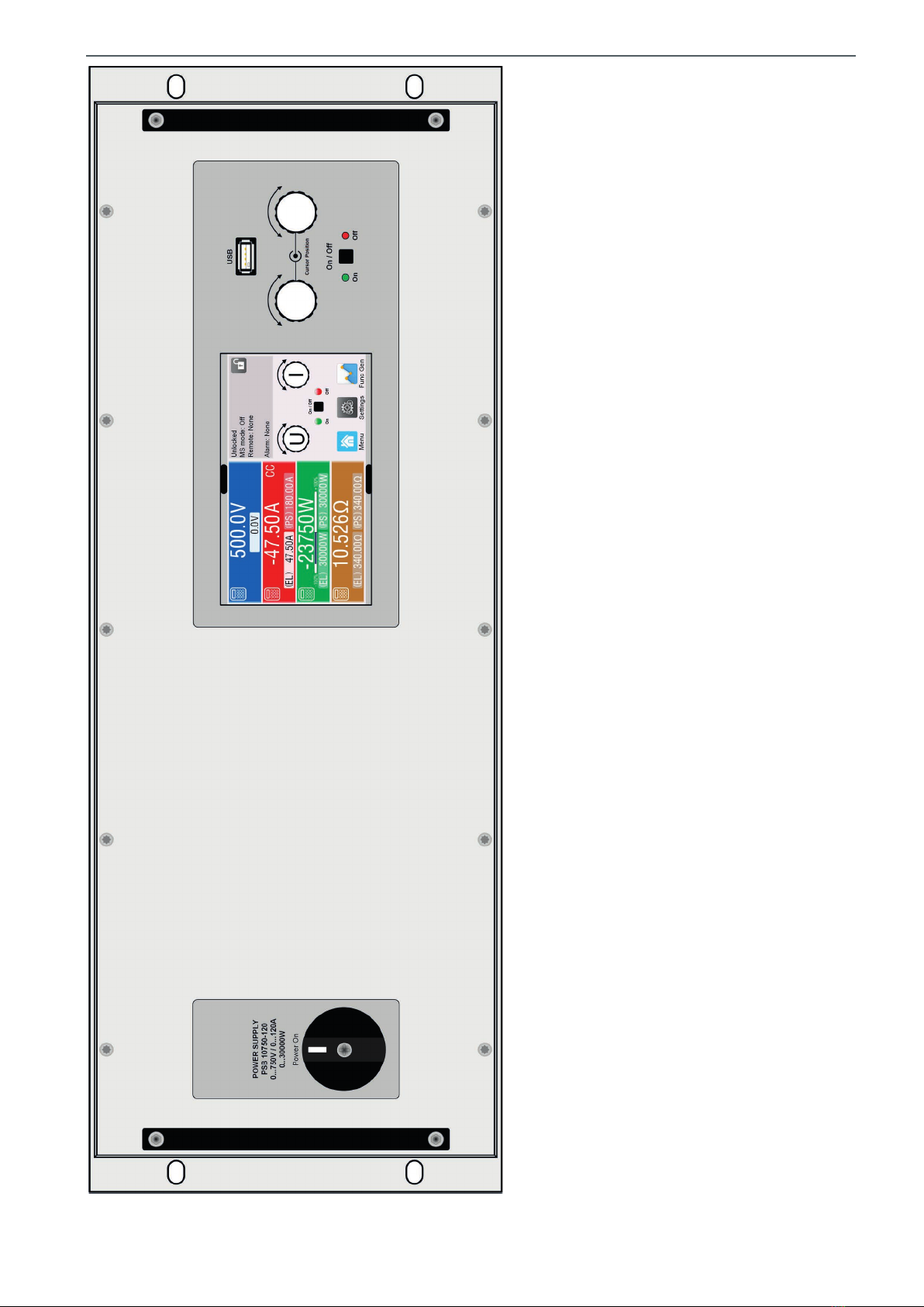
ERS COMPACT
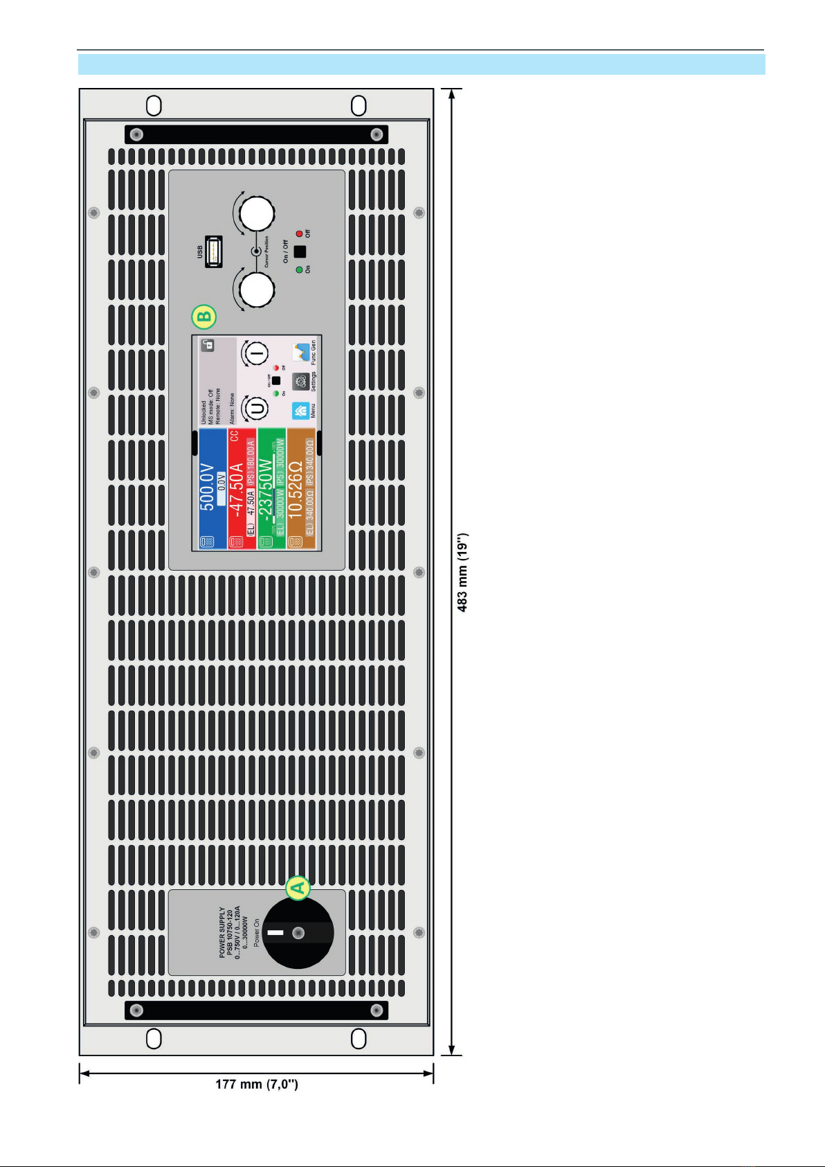
A - Power switch
B - Control panel
Figure 1-Frontview(standardversion)
1.8.5 Views
Heinzinger electronic GmbH Phone: +49 (0) 8031 2458 0 www.heinzinger.com
Anton-Jakob-Str. 4, 83026 Rosenheim Fax: + 49 (0) 8031 2458 58 info@heinzinger.de
Germany
Page 18
ERS COMPACT
Figure 2-Frontview(water-cooledversion)
Heinzinger electronic GmbH Phone: +49 (0) 8031 2458 0 www.heinzinger.com
Anton-Jakob-Str. 4, 83026 Rosenheim Fax: + 49 (0) 8031 2458 58 info@heinzinger.de
Germany
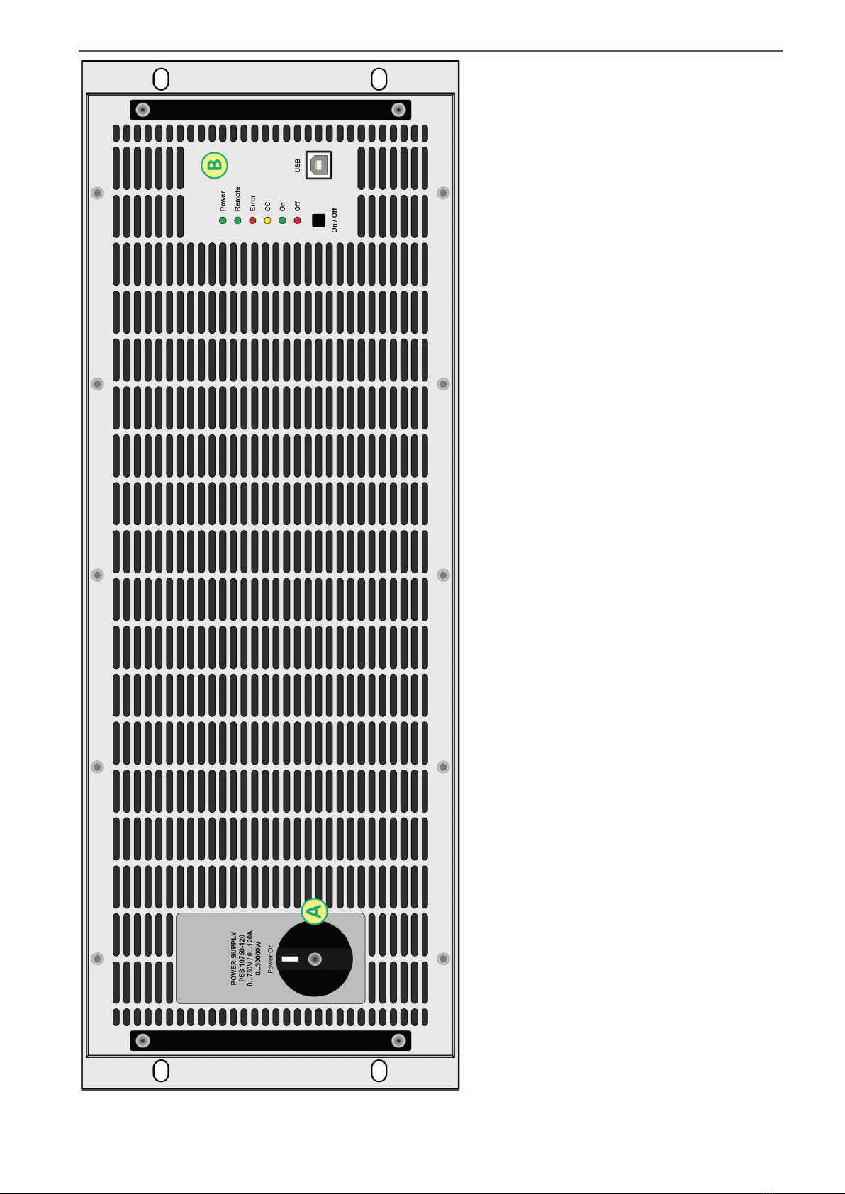
Page 19
ERS COMPACT
Figure 3-Frontview(Slaveversion)

Heinzinger electronic GmbH Phone: +49 (0) 8031 2458 0 www.heinzinger.com
Anton-Jakob-Str. 4, 83026 Rosenheim Fax: + 49 (0) 8031 2458 58 info@heinzinger.de
Germany
Page 20
ERS COMPACT
C-Controlinterfaces(digital,analog) F - Share Bus connectors J - AC plug
D-Master-slavebusports G-DCterminal(type1shown)
E - Remote sensing connection H-ACinputlter
Figure 4-Rearview(standardversion)
This manual suits for next models
9
Table of contents
Other heinzinger Power Supply manuals


Popular Power Supply manuals by other brands

EA-ELEKTRO-AUTOMATIK
EA-ELEKTRO-AUTOMATIK EA-PS 500 Series User instruction guide

Analytic Systems
Analytic Systems IBI Series Installation & operation manual

Agilent Technologies
Agilent Technologies U8030A Series user guide

Goobay
Goobay 53439 user manual

FEAS
FEAS PSU500T-K operating instructions

Philips
Philips PDS-150e Product guide


