Heinzmann PRIAMOS I Series User manual

Heinzmann GmbH & Co. KG
Engine & Turbine Controls
Am Haselbach 1
D-79677 Schönau (Schwarzwald)
Germany
Phone +49 7673 8208-0
Fax +49 7673 8208-188
www.heinzmann.com
V.A.T. No.: DE145551926
HEINZMANN®
Digital Electronic Speed Governors
Basic Systems
PRIAMOS I
DC 16.1-03
DC 30.1-03
DC 40.1-03
Copyright 2006 by Heinzmann GmbH & Co KG. All rights reserved. This document may not be reproduced or handed on to third parties.
Manual DG 93 101-e / 04-06


PRIAMOS I
Priamos I
for engines up to approx. 4000 kW
Basic SystemDG 161 - 03
D :
Digital
DG :
Digital Governor (Basic System)
DC :
Digital Control Unit
StG : Actuator (Stellgerät)
SW : Setpoint Potentiometer (Sollwertpot.)
IA : Pickup (Impulsaufnehmer)
Control Unit DC 161 - 03
Actuator StG 16 - 01
Setpoint Pot. SW ...
Pickup IA ...
Basic SystemDG 301 - 03
Control Unit DC 301 - 03
Actuator StG 30 - 01
Setpoint Pot. SW ...
Pickup IA ...
Basic SystemDG 401 - 03
Control Unit DC 401 - 03
Actuator StG 40 - 01
Setpoint Pot. SW ...
Pickup IA ...

Read this entire manual and all other publications appertaining to the
work to be performed before installing, operating or servicing your
equipment.
Practice all plant and safety instructions and precautions.
Failure to follow instructions may result in personal injury and/or
damage to property.
HEINZMANN will refuse all liability for injury or damage which
results from not following instructions
Please note before commissioning the installation:
Before starting to install any equipment, the installation must have been
switched dead!
Be sure to use cable shieldings and power supply connections meeting
the requirements of the European Directive concerning EMI.
Check the functionality of the existing protection and monitoring
systems.
To prevent damages to the equipment and personal injuries, it is
imperative that the following monitoring and protection systems
have been installed:
Overspeed protection acting independently of the speed governor
Overtemperature protection
HEINZMANN will refuse all liability for damage which results from
missing or insufficiently working overspeed protection
Generator installation will in addition require:
Overcurrent protection
Protection against faulty synchronization due to excessive frequency,
voltage or phase differences
Reverse power protection
Overspeeding can be caused by:
Failure of the voltage supply
Failure of the actuator, the control unit or of any accessory device
Sluggish and blocking linkage
Warning
Danger
Danger
Danger!
High
Voltage
Danger

Electronically controlled injection (MVC) will in addition require
to observe the following:
With Common Rail systems a separate mechanical flow limiter must
be provided for each injector pipe.
With Pump-Pipe-Nozzle (PPN) and Pump Nozzle (PNE) systems fuel
release may be enabled only by the movement of control piston of the
solenoid valve. This is to inhibit fuel from being delivered to the
injection nozzle in case of seizure of the control piston.
The examples, data and any other information in this manual are
intended exclusively as instruction aids and should not be used in any
particular application without independent testing and verification by
the person making the application.
Independent testing and verification are especially important in any
application in which malfunction might result in personal injury or
damage to property.
HEINZMANN make no warranties, express or implied, that the
examples, data, or other information in this volume are free of error,
that they are consistent with industry standards, or that they will meet
the requirements for any particular application.
HEINZMANN expressly disclaim the implied warranties of
merchantability and of fitness for any particular purpose, even if
HEINZMANN have been advised of a particular purpose and even if a
particular purpose is indicated in the manual.
HEINZMANN also disclaim all liability for direct, indirect, incidental
or consequential damages that result from any use of the examples,
data, or other information contained in this manual.
HEINZMANN make no warranties for the conception and engineering
of the technical installation as a whole. This is the responsibility of the
user and of his planning staff and specialists. It is also their
responsibility to verify whether the performance features of our devices
will meet the intended purposes. The user is also responsible for correct
commissioning of the total installation.
Warning
Warning
Danger

Contents
PRIAMOS I
Contents
Page
1 Safety Instructions and Related Symbols............................................................................ 1
1.1 Basic Safety Measures for Normal Operation................................................................. 2
1.2 Basic Safety Measures for Servicing and Maintenance .................................................. 2
1.3 Before Putting an Installation into Service after Maintenance and Repair Works.......... 3
2 General Remarks................................................................................................................... 4
3 Mode of Operation................................................................................................................ 7
4 Block Diagram of the Digital Governor DG 16.1 - 03 up to DG 40.1 - 03........................ 8
5 Sensors.................................................................................................................................... 9
5.1 Overview ......................................................................................................................... 9
5.2 Magnetic Pickup IA ...................................................................................................... 10
5.2.1 Technical Datas...................................................................................................... 10
5.2.2 Installation ............................................................................................................. 10
5.2.3 Tooth Profile.......................................................................................................... 11
5.2.4 Clearance for IA 02 - 76 up to IA 13 - 102............................................................ 11
5.2.5 Clearance for IA 22 - 76 and IA 23 - 102.............................................................. 11
5.2.6 Mounting Measurements ....................................................................................... 12
5.2.7 Redundant Speed Signal........................................................................................ 12
5.3 Cooling Medium Temperature Sensor TS 01 - 28 - PT 1000 ....................................... 13
5.4 Pressure Sensors............................................................................................................ 14
5.4.1 Oil Pressure Sensor................................................................................................ 14
5.4.2 Boost Pressure Sensors.......................................................................................... 15
5.4.2.1 Boost Pressure Sensor with Plug ................................................................... 15
5.4.2.2 Boost Pressure Sensor with Housing and Terminal Strip.............................. 16
6 Speed Setpoint Adjusters.................................................................................................... 17
6.1 Setpoint Potentiometer SW 01 - 1 - b (1 turn)............................................................... 17
6.2 Setpoint Potentiometer SW 02 - 10 - b (10- turn)......................................................... 17
6.3 Setpoint Value Adjustment by Current Signal.............................................................. 18
6.4 Digital Presetting of Setpoint Values ............................................................................ 18
6.5 Setpoint Value Adjustment by Pedal............................................................................. 18
6.6 Pneumatic Setpoint Adjusters........................................................................................ 18
7 Control Unit DC 16.1 - 03 up to DC 40.1 - 03................................................................... 19
7.1 Specification.................................................................................................................. 19
7.2 Measurements................................................................................................................ 20

Contents
PRIAMOS I
8 Actuators.............................................................................................................................. 21
8.1 Design and Mode of Operation ..................................................................................... 21
8.2 Installation..................................................................................................................... 22
8.3 Specification.................................................................................................................. 23
8.4 Measurements................................................................................................................ 25
9 Regulating Linkage............................................................................................................. 26
9.1 Length of Lever Arm..................................................................................................... 26
9.2 Order Specification for Lever Arm ............................................................................... 26
9.3 Connecting Linkage....................................................................................................... 26
9.4 Linkage Adjustment for Diesel Engines........................................................................ 27
9.5 Linkage Adjustment for Carburettor Engines ............................................................... 28
10 Electric Connection........................................................................................................... 29
10.1 Connection of Shielding.............................................................................................. 29
10.2 Connection of Power Supply....................................................................................... 30
10.3 Example of Connection for Generator Set with digital Accessories........................... 32
10.4 Example of Connection for Generator Set with analogue Accessories....................... 33
10.5 Example of Connection for Vehicle Operation........................................................... 34
10.6 Example of Connection for Locomotive Operation with 16 Notches......................... 35
10.7 Example of Connection for Locomotive Operation with Speed Setpoint via Current
Signal................................................................................................................................... 36
10.8 Example of Connection for Marine Operation with Master/Slave.............................. 37
10.9 Example of Connection for Marine Operation in single Operation............................ 38
11 Harness............................................................................................................................... 39
11.1 Cable Lenghts.............................................................................................................. 39
11.2 Plug Designations........................................................................................................ 40
12 Programming Possibilities................................................................................................ 41
12.1 Programming by the Manufacturer ............................................................................. 41
12.2 Programming with the Hand- Held Programmer 2 ..................................................... 41
12.3 Programming by PC .................................................................................................... 41
12.4 Programming with User Masks................................................................................... 41
12.5 Transferring Data Sets................................................................................................. 41
12.6 Assembly Line End Programming .............................................................................. 42
13 Starting the Engine - Brief Instructions.......................................................................... 43
14 Ordering Specifications .................................................................................................... 44
14.1 General ........................................................................................................................ 44
14.2 Cable Length ............................................................................................................... 44
15 Figure List.......................................................................................................................... 47


1 Safety Instructions and Related Symbols
PRIAMOS I 1
1Safety Instructions and Related Symbols
This publication offers wherever necessary practical safety instructions to indicate inevitable
residual risks when operating the engine. These residual risks imply dangers to
persons
product and engine
environment.
The symbols used in this publication are in the first place intended to direct your attention to
the safety instructions!
This symbol is to indicate that there may exist dangers to the engine, to the
material and to the environment.
This symbol is to indicate that there may exist dangers to persons. (Danger
to life, personal injury))
This symbol is to indicate that there exist particular danger due to
electrical high tension. (Mortal danger).
This symbol does not refer to any safety instructions but offers important notes for
better understanding the functions that are being discussed. They should by all
means be observed and practiced. The respective text is printed in italics.
The primary issue of these safety instructions is to prevent personal injuries!
Whenever some safety instruction is preceded by a warning triangle labelled “Danger” this is
to indicate that it is not possible to definitely exclude the presence of danger to persons,
engine, material and/or environment.
If, however, some safety instruction is preceded by the warning triangle labelled “Caution”
this will indicate that danger of life or personal injury is not involved.
The symbols used in the text do not supersede the safety instructions. So please do not
skip the respective texts but read them thoroughly!
Note
Warning
Dan
g
er
Danger!
High
V
olta
g
e

1 Safety Instructions and Related Symbols
2PRIAMOS I
In this publication the Table of Contents is preceded by diverse instructions that
among other things serve to ensure safety of operation. It is absolutely imperative
that these hints be read and understood before commissioning or servicing the
installation.
1.1 Basic Safety Measures for Normal Operation
•The installation may be operated only by authorized persons who have been duly
trained and who are fully acquainted with the operating instructions so that they are
capable of working in accordance with them.
•Before turning the installation on please verify and make sure that
- only authorized persons are present within the working range of the engine;
- nobody will be in danger of suffering injuries by starting the engine.
•Before starting the engine always check the installation for visible damages and make
sure it is not put into operation unless it is in perfect condition. On detecting any faults
please inform your superior immediately!
•Before starting the engine remove any unnecessary material and/or objects from the
working range of the installation/engine.
•Before starting the engine check and make sure that all safety devices are working
properly!
1.2 Basic Safety Measures for Servicing and Maintenance
•Before performing any maintenance or repair work make sure the working area of the
engine has been closed to unauthorized persons. Put on a sign warning that
maintenance or repair work is being done.
•Before performing any maintenance or repair work switch off the master switch of the
power supply and secure it by a padlock! The key must be kept by the person
performing the maintenance and repair works.
•Before performing any maintenance and repair work make sure that all parts of engine
to be touched have cooled down to ambient temperature and are dead!
•Refasten loose connections!
•Replace at once any damaged lines and/or cables!
•Keep the cabinet always closed. Access should be permitted only to authorized
persons having a key or tools.

1 Safety Instructions and Related Symbols
PRIAMOS I 3
•Never use a water hose to clean cabinets or other casings of electric equipment!
1.3 Before Putting an Installation into Service after Maintenance and Repair
Works
•Check on all slackened screw connections to have been tightened again!
•Make sure the control linkage has been reattached and all cables have been
reconnected.
•Make sure all safety devices of the installation are in perfect order and are working
properly!

2 General Remarks
PRIAMOS I
4
2General Remarks
HEINZMANN digital governors with control units DC 16.1-03 up to DC 40.01-03 constitute
speed governors offering a wide range of functions.
In addition to speed regulation, the following functions are available:
a) Starting Fuel Flow Adjustment
When setting starting fuel flow, starting minimum fuel flow or starting maximum fuel flow
are available as alternatives. If nesessary, both als can be depent on temperature. Furthermore,
variable starting fuel flow can be provided, by which starting fuel flow is increased
automatically during start-up.
b) Speed Ramp
For applications in which speed is not supposed to respond as fast as possible to changes of
setpoint values (e.g., locomotive operation), a speed ramp is available which according to
requirements may be programmed separately for increasing or decreasing speed.
c) Fixed Fuel Limitation
For the stop-position and the maximum fuelling position "electric catches" can be provided.
This will prevent the governor's thrust from affecting the terminal stops of the injection pump,
etc.
d) Speed Dependent Fuel Limitation
For variable speed governors, there is provided an option of programming speed dependent
limit curves. Thus, for any speed, torque can be reduced as is permissible for the engine or
desired by the user.
e) Boost Pressure Dependent Fuel Limitation
For turbocharged engines, fuelling can be reduced to achieve smokeless operation in case of
missing boost pressure (e.g., starting or load change). The respective limit curves can be
programmed accordingly.
f) Idling and Maximum Speed Control
For vehicle application, the governor can be made to operate as an idling and maximum speed
controller. In addition, one fixed intermediate speed is available, e.g., for an application
combining driving and stationary mode (e.g., generator at power take-off). If necessary, a

2 General Remarks
PRIAMOS I 5
5
change-over switching of the droop can be provided, i.e., during stationary operation also
droop zero is possible
g) Temperature Dependent Idling Speed
For low temperatures, the engine can be run at some higher idling speed. With the engine
warming up, idling speed is reduced to its normal value.
h) Oil Pressure Monitoring
For the purpose of oil pressure monitoring, speed/pressure dependent limit curves can be
provided. If oil pressure is too low, an alarm is given; if oil pressure continues to drop, the
engine is shut down.
i) Load Regulation System
For diesel-electric locomotive operation, a load regulation system can be provided, by which
generator output is regulated in dependence on speed resp. load.
j) Anti Stick Slip Device
For locomotive operation, an anti stick slip device can be provided.
k) Accessories
Accessories such as synchronizing units, load measuring units, disturbance variable
compensation units can be connected via a CAN-Bus within the control unit. The CAN-Bus
may also be used to implement load distribution by equal fuelling (e.g., two engines on one
gear).
l) Output Signals
For speed and actuator travel, proportional signals are available in the range of
4–20 mA. They can be used for purposes of display or for further processing (e.g., switches).
m) Operating Data Storage
On request, operating data storage can be provided, by which in cases of disturbances and
failures the causes may be traced back even at some later time.
Furthermore, if errors occur at the sensors or within the control system, an alarm is given.

2 General Remarks
PRIAMOS I
6
When selecting and determining the functions, it has to be ascertained whether
the hardware equipment suffices with respect to the total range of functions.
Note

3 Mode of Operation
PRIAMOS I 7
3Mode of Operation
The actual speed of the engine is read by a pulse pickup from a cog wheel, preferably from
the starter gear. The microprocessor (CPU) of the control unit compares the actual speed with
the preset value. If differences are stated, the new actuator signal is calculated by the CPU and
transmitted to the actuator via the output stage. Feedback from the actuator indicates the
current position of the output shaft thus allowing optimum signal adjustment by the CPU.
As the governor comprises an I-fraction and as for any load level the speed is permanently
compared with a fixed preset value, speed can be kept constant also in steady state, i.e., droop
is zero.
For applications requiring droop, the speed related to the respective fuelling is calculated by
the CPU and entered as correction of the setpoint value.
During standstill, a particular circuit ensures that only the current of the control unit is
received by the governor, but no current flows to the actuator motor.
4 Block Diagram of the Digital Governor DG 16.1 - 03 up to DG 40.1 - 03
8PRIAMOS I
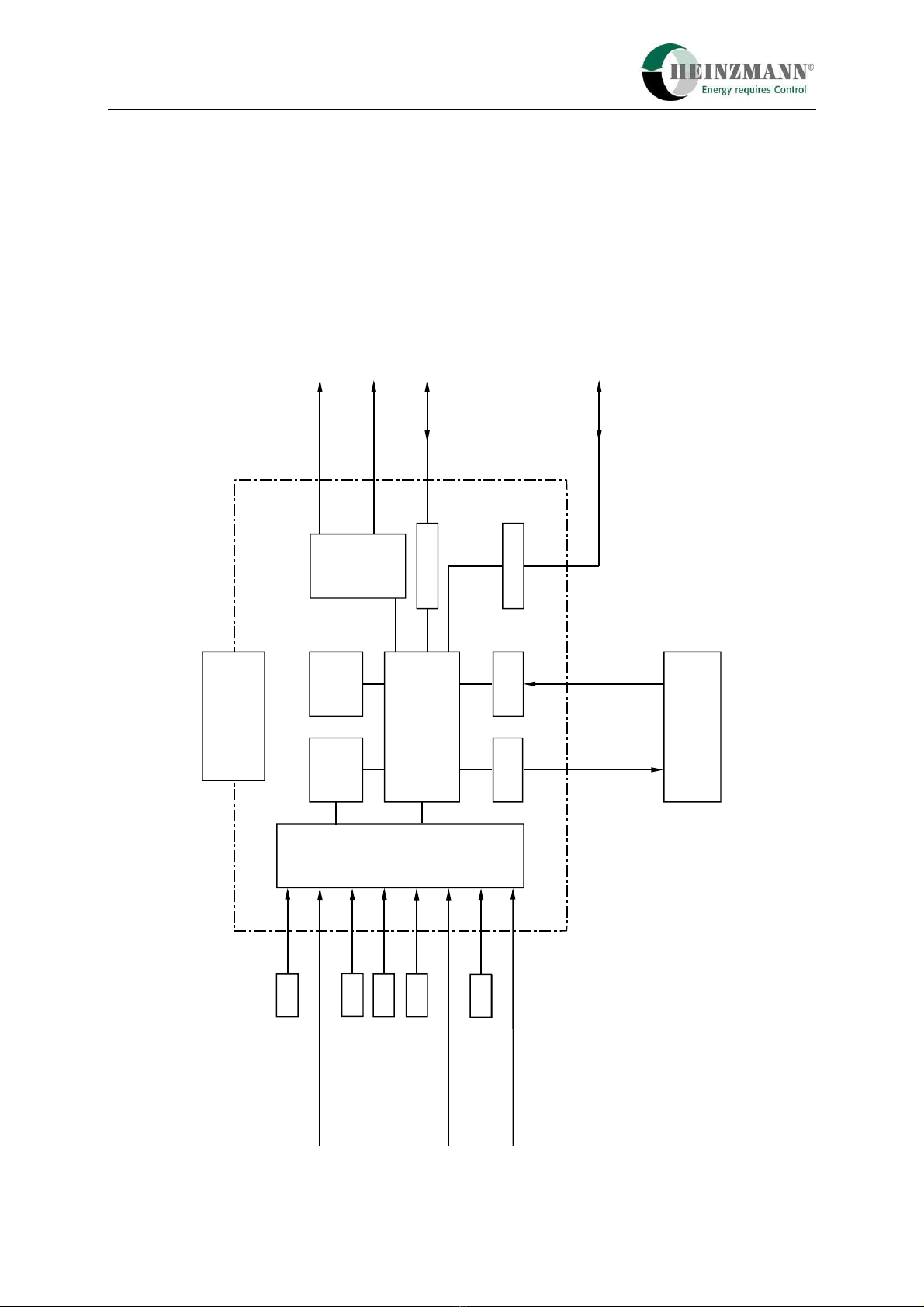
4Block Diagram of the Digital Governor DG 16.1 - 03 up to DG 40.1 - 03
Memory
Mikroprocessor
Power CAN - Bus
Interface
Control Unit
DC 641 03 /
DC 901 - 03
Magnetic pickup
Redundant Engine Speed Signal
Setpoint Values
Temperature Sensor
Engine Stop
Oil Pressure Sensor
Digital Inputs
Actuator
StG 64 - 03 /
StG 90 - 03
Engine Speed
Actuator Travel
Alarm
Programming Attachment
Diagnostics
Digital Application Units
e.g. Synchronizer, Load
Measuring Unit
Additional
Processor
Converter
Converter
Converter
Boost Pressure
Sensor
Amplifier
Feedback
Drive
Figure 1: Blockdiagram DG 16.1 - 03 up to DG 40.1 - 03

5 Sensors
PRIAMOS I 9
5Sensors
5.1 Overview
Sensor Speed
Coolant
Temperature Oil Pressure Boost Pressure
HZM Designation IA .. TS 01-28-PT1000 DSO 01-6
DSO 01-10
DSO 01-16
DSL/G 0..-2
DSL/G 0..-5
DSL/G 0..-10
Connection SV 6-IA-2K
2 pole
SV 6-IA-2K
2 pole
DIN 43650 A
2 Line System
DIN 43650 A
2 Line System
Measuring Procedure inductive, active PT1000, passive active active
Measuring Range 50...6.000 Hz -50...+150°C 0...6 bar
0...10 bar
0...2 bar
0...5 bar
0...10 bar
Supply Voltage
Range passive 10...34 V DC 12...36 V DC
Output Signal Range 0...10 V AC ca. 700...1500 Ohm 4...20 mA 4...20 mA
Operating
Temperature Range -55...+120°C -50...+150°C -25...+125°C -40...+100°C
In order to ensure maximum flexibility with regard to the sensors, the minimum/ maximum
current values and the measuring ranges of the pressure and temperature sensors have been
provided programmable.

5 Sensors
10 PRIAMOS I
5.2 Magnetic Pickup IA ...
5.2.1 Technical Datas
Operating principle inductive sensor
Distance from sensing gear standard 0.5 to 0.8 mm
with IA 22.. and IA 23.. 2.5 to 3 mm
Output 0 V .. 10 V AC
Signal form Sine (depending on tooth shape)
Resistance approx. 52 Ohm, with IA 22.. and IA 23..
approx. 130 Ohm
Temperature range -55°C up to +125°C
Protection grade IP 55
Vibration < 10g, 10 .. 100 Hz
Shock < 50g, 11 ms half sine wave
Corresponding plug SV 6 - IA - 2K (EDV- No.: 010-02-170-00)
5.2.2 Installation
The installation of the pickup has to be arranged in such a way as to obtain a frequency
as high as possible. Normally, the HEINZMANN digital governors DG 16.1 - 03 up to
DG 40.1 - 03 are designed for a maximum frequency of 6.000 Hz. The frequency (by
Hz) is calculated according to the formula:
f
(Hz) =
z = number of teeth on the pickup wheel
Example:
n = 500
z = 80
f = = 666.67 Hz
It should be taken care that the speed can be measured by the pulse pickup without any
bias. For best results therefore, the speed pickup should take the engine speed from the
crankshaft. A suitable position for this is, e.g., the starter gear (but not the injection
pump wheel).
The pickup gear must consist of magnetic material (e.g., steel, cast iron).
This manual suits for next models
3
Table of contents
Other Heinzmann Industrial Equipment manuals


Popular Industrial Equipment manuals by other brands


MBW
MBW R442 Operator's safety and service manual

MÄDLER
MÄDLER Accuride DZ 5417 Installation guides

KTR-Group
KTR-Group CLAMPEX 620 Operating & assembly instructions

Morgana
Morgana AutoCreaser Pro 50 Service manual

Pepperl+Fuchs
Pepperl+Fuchs KCD2-SLD-Ex1.1045 instruction manual

ABB
ABB HT562800 Operation manual

Mitsubishi Electric
Mitsubishi Electric NZ2GFCF-D62PD2 user manual

HSB
HSB Gamma 90-ZSSD Original Assembly and Maintenance Instructions

ABB
ABB XAC25744 Operation manual

M2I
M2I CTOP2 Series user manual

Renishaw
Renishaw RLP40 quick start guide

Siemens
Siemens SIRIUS 3SE39 C 20 Series Original operating instructions