Heinzmann StG 40.90-09 PD User manual

Copyright 2010 by Heinzmann GmbH & Co. KG. All rights reserved.
This publication may not be reproduced by any means whatsoever or passed on to any third parties.
5369 Manual DG 10 009-e / 06-10
Heinzmann GmbH & Co. KG
Engine & Turbine Management
Am Haselbach 1
D-79677 Schönau
Germany
Phone +49 7673 8208 - 0
Fax +49 7673 8208 - 188
www.heinzmann.com
V.A.T. No.: DE145551926
HEINZMANN
Engine & Turbine Management
Digital Positioning System
StG 40.90-09 PD
Instruction manual
(original instructions)
The appropriate manuals must be thoroughly studied before
installation, initial start-up and maintenance.
All instructions pertaining to the system and safety must be followed in
full. Non-observance of the instructions may lead to injury to persons
and/or material damage.
HEINZMANN shall not be held liable for any damage caused through
non-observance of instructions.
Independent tests and inspections are of particular importance for all
applications in which a malfunction could result in injury to persons or
material damage.
All examples and data, as well as all other information in this manual
are there solely for the purpose of instruction and they may not be used
for special application without the operator running independent tests
and inspections beforehand.
HEINZMANN does not guarantee, neither expressly nor tacitly, that
the examples, data or other information in this manual is free from
error, complies with industrial standards or fulfils the requirements of
any special application.
To avoid any injury to persons and damage to systems, the following
monitoring and protective systems must be provided:
overspeed protection independent of the rpm controller
HEINZMANN shall not be held liable for any damage caused through
missing or insufficiently rated overspeed protection.
thermal overload protection
The following must also be provided for alternator systems:
Overcurrent protection
Protection against faulty synchronisation for excessively-large
frequency, voltage or phase difference
Directional contactor
The reasons for overspeeding may be:
Failure of positioning device, control unit or its auxiliary devices
Linkage sluggishness and jamming
The following must be observed before an installation:
Always disconnect the electrical mains supply before any
interventions to the system.
Only use cable screening and mains supply connections that
correspond with the European Union EMC Directive
Check the function of all installed protection and monitoring systems

Please observe the following for electronically controlled injection
(MVC):
For common rail systems each injector line must be equipped with a
separate mechanical flow-rate limiter.
For unit pump (PLD) and pump-injector unit (PDE) systems, the
fuel enable is first made possible by the solenoid valve’s control
plunger motion. This means that in the event of the control plunger
sticking, the fuel supply to the injection valve is stopped.
As soon as the positioning device receives power, it can actuate the
controller output shaft automatically at any given time. The range of
the controller shaft or control linkage must therefore be secured against
unauthorised access.
HEINZMANN expressly rejects any implied guarantee pertaining to
any marketability or suitability for a special purpose, including in the
event that HEINZMANN was notified of such a special purpose or the
manual contains a reference to such a special purpose.
HEINZMANN shall not be held liable for any indirect and direct
damage nor for any incidental and consequential damage that results
from application of any of the examples, data or miscellaneous
information as given in this manual.
HEINZMANN shall not provide any guarantee for the design and planning
of the overall technical system. This is a matter of the operator its planners
and its specialist engineers. They are also responsible for checking whether
the performances of our devices match the intended purpose. The operator is
also responsible for a correct initial start-up of the overall system.

Contents
Digital Positioning Systems
Contents
Page
1 Safety Instructions and Related Symbols ........................................................................... 1
1.1 Safety Measures for Positioning Devices........................................................................ 2
1.2 Safety Measures under Normal Operation ...................................................................... 3
1.3 Safety Measures for Maintenance and Servicing ............................................................ 3
2 Application and Function ..................................................................................................... 4
2.1 Proper and intended use................................................................................................... 4
2.2 Function description ........................................................................................................ 4
2.3 Functional Block Diagram .............................................................................................. 6
3 Specifications of Positioning System StG 40.90-09 PD ...................................................... 7
3.1 Design and Mode of Operation ....................................................................................... 7
3.2 Electrical Specification.................................................................................................... 8
3.3 Actuator Specification ..................................................................................................... 9
3.4 Dimensions .................................................................................................................... 10
4 Installation and Regulating Linkage ................................................................................. 11
4.1 Installation ..................................................................................................................... 11
4.2 Regulating Linkage ....................................................................................................... 11
4.2.1 Length of Lever Arm ............................................................................................. 11
4.2.2 Connecting Linkage............................................................................................... 11
4.2.3 Linkage Adjustment for Diesel Engines................................................................ 12
4.2.4 Linkage Adjustment for Carburettor Engines........................................................ 13
5 Electrical Connection.......................................................................................................... 14
5.1 Pin Assignment.............................................................................................................. 14
5.2 Connection of Power Supply......................................................................................... 14
6 Figure List............................................................................................................................ 16
7 Download of Manuals ......................................................................................................... 17
8 Declaration of Incorporation ............................................................................................. 18

1 Safety Instructions and Related Symbols
1Safety Instructions and Related Symbols
This publication offers practical safety instructions to indicate the unavoidable residual risks
involved when operating the machine. These residual risks involve hazards to
- Personnel
- Product and machine
- The environment
The primary aim of the safety instructions is to prevent personal injury!
The signal words used in this publication are specifically designed to direct your attention to
possible damage extent!
DANGER indicates a hazardous situation the consequence of which could
be fatal or severe injuries if it is not prevented.
WARNING indicates a hazardous situation which could lead to fatal
injury or severe injuries if it is not prevented.
CAUTION indicates a hazardous situation which could lead to minor
injuries if it is not prevented.
NOTICE indicates possible material damage.
Safety instructions are not only denoted by a signal word but also by
hazard warning triangles. Red hazard warning triangles indicate
immediate danger to life. Yellow hazard warning triangles indicate a
possible risk to life and limb. Hazard warning triangles can contain
different symbols to illustrate the danger. However, the symbol used is no
substitute for the actual text of the safety instructions. The text must
therefore always be read in full!

1 Safety Instructions and Related Symbols
In this publication the Table of Contents is preceded by diverse instructions that
among other things serve to ensure safety of operation. It is absolutely imperative that
these hints be read and understood before commissioning or servicing the installation.
1.1 Safety Measures for Positioning Devices
This machine has been designed for reliable utilisation in accordance with the application,
conditions and specifications as described in these instructions. Everyone who works on
this machine must have read these instructions and the information. The employer or safety
officer bear responsibility for ensuring that these instructions are known and adhered to.
High weight of positioning device
Risk of crushing or bone injuries caused by device falling down
Wear safety shoes when transporting the device
Mechanical protection devices against falling down
Use suitable hoisting gear
Device gets hot
Risk of burn injuries
Always allow positioning device to cool down first before working on it
Wear suitable protective clothing
Risk of damage to positioning device through improper use!
Installation, maintenance and operation to be conducted by skilled
personnel only.
Never use a high-pressure cleaner for cleaning the device

1 Safety Instructions and Related Symbols
1.2 Safety Measures under Normal Operation
The system may be operated by qualified and authorised personnel only,
who are both familiar with the operating instructions and who can carry
them out!
Before switching on the system, check and ensure that:
only authorised personnel are in the machine’s operating range
no-one can be injured by the machine starting up
Before each start of the motor:
Always check the system for visible damage and ensure it is not put into
operation unless it is in perfect condition! Always notify the responsible
department immediately about any defects
Check and ensure that all safety devices are in proper working condition
Remove all material and objectives surplus to requirements from the operating
range of the system or motor
1.3 Safety Measures for Maintenance and Servicing
Before starting maintenance or repair work:
Block off access to the machine’s working area for unauthorised persons!
Put up an information board that indicates that such work is underway
Switch off main switch for mains supply and secure with a padlock! The key
to the padlock must be held by the person carrying out the maintenance or
repair work
Ensure that all parts that are capable of being touched have cooled down to
ambient temperature and have been isolated from the mains
Re-fasten loose connections
Replace any damaged lines or cables immediately
Keep the switch cabinet closed at all times! Access is solely for authorised
persons with key/tools
Never use a water spray or high-pressure cleaners on switch cabinets and
other electrical equipment enclosures for cleaning purposes! Risk of short
circuit and corrosion to positioning device

2 Application and Function
2Application and Function
2.1 Proper and intended use
The positioning devices StG 40.90-09 PD is to be used solely for control applications on
machines. It is intended for use in an industrial environment. When operated outdoors,
additional protective measures against weather are also required.
Signals are exchanged electrically. Because transmission may be interfered with by external
circumstances or influences, the user must provide additional safety devices to match the application
case.
In individual cases, the following must be coordinated with the manufacturer HEINZMANN:
Each use which deviates from the above mentioned
Modifications to the device
Use in extreme, ambient conditions that deviate from the specification
(dust, temperature, wetness)
Use under powerful electrical or electromagnetic fields
Use in aggressive atmospheres or vapours
Use in potentially explosive areas
A written opinion from the manufacturer must always be procured in the event of any
obscurities, queries or missing statement.
2.2 Function description
Positioning devices StG 40.90-09 PD is an electrical positioner with a rotating output shaft. It
can be used for a wide range of control applications or in conbination with superior control
systems for control purposes of any kind.
It is actuated by an external, electrical position set point signal, and thereby automatically
regulates the mechanical position of its output shaft. The position set point can be transmitted
to it as a current, voltage or PWM signal, depending on preattunement.. For operation the
device requires a power supply. The use of these positioners, in contrast to where positioning
2 Application and Function
devices are regulated directly by controllers, can be a practical option when more stringent
requirements are placed on control accuracy.
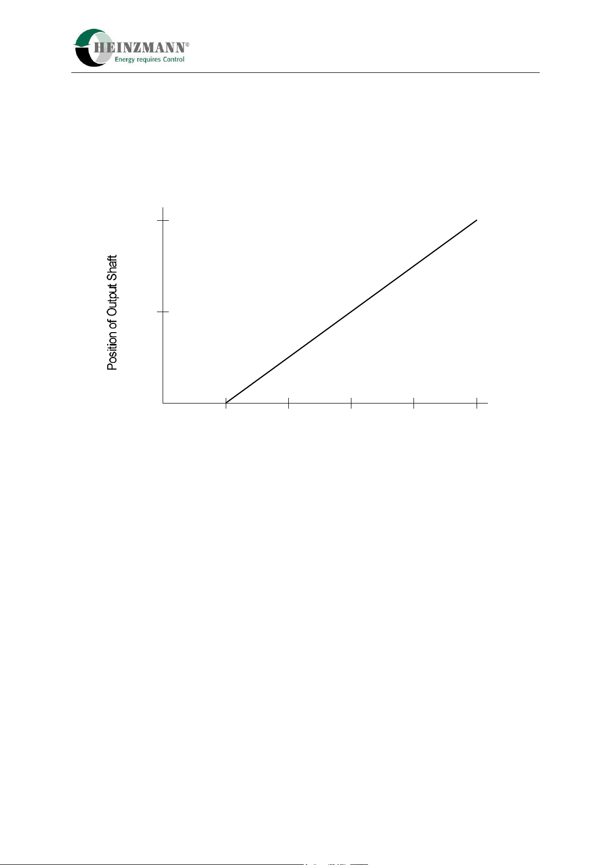
In positioners, there is a proportional correlation between the position of the actuator output
shaft and a command input signal. The following curve shows this relation for the
4 – 20 mA input signal exemplary.
4 8 12 16 20 m
A
50 %
100 %
0
Input Signal
Figure 1: Example for relation between current input signal and position
The input signal, i.e. the position setpoint for the actuator output shaft is sent to an
actual/setpoint comparator receiving the actual value from the actuator feedback. Subsequent
signal processing for position control is performed by a microcontrol.
The position control circuit incorporates a 4-quadrant amplifier which allows to drive the
actuator electrically in either direction. This ensures optimum utilization of the actuator's
rotational force. Together with very low current consumption in steady state operation heat
build-up in the actuator also is reduced.
The feedback signal, i.e. the output shaft position signal, is available as an electrical signal. It
can be used as well for further processing as for indicating actuator position.
Due to the programable microcontrol a lot of functions and capabilities of the positioning
devices StG 40.90-09 PD can be determined by parameterization. This offers various options
for the systems setting up and its configuration.
For instance linear output characteristic, range, type and sense of input and output etc. can be
adapted to users requirements.

2 Application and Function
2.3 Functional Block Diagram
Figure 2: Functional block diagram

3 Specifications of Positioning System StG 40.90-09 PD
3Specifications of Positioning System StG 40.90-09 PD
3.1 Design and Mode of Operation
Torque is generated by a DC disc armature motor and transmitted to the governor
output shaft by way of a gearbox.
A feedback cam is mounted on the governor output shaft which is scanned contactlessly
by a probe, thus providing the precise position of the output shaft as electrical signal.
If the actuator strikes against a stop, as may be caused by engine overload or cylinder
failure, the current limitation will take effect after approx. 20 seconds; by this the
current to the actuator is reduced to a value that cannot harm the motor.
Figure 3: Principle of StG 40.90-09 PD
Altogether, this type of positioner offers following advantages:
- High regulating power working in either direction.
- Extremely low current consumption during steady state and relatively low current
consumption on changes of load.
- Indifference to slow voltage changes of power supply; abrupt voltage changes,
however, will cause governor disturbances.
Positioning
control system
DC disc motor
Feedback cam Feedback probe
Gearbox

3 Specifications of Positioning System StG 40.90-09 PD
3.2 Electrical Specification
nom. supply voltage 24 V DC
max. voltage 33 V DC
min. voltage 16 V DC
maximum ripple voltage at max. actuator current 10 % at 100 Hz
acceptable voltage drop at max. actuator current max. 10 % at control unit
fuse protection 10 A (external, by user)
current consumption approx. 300 mA,
additionally current of actuator
steady state variation ±0.25 %.
storage temperature -40°C to +105°C.
operating ambient temperature -25°C to +90°C.
humidity up to 98 %
Input “command”
proportional input
alternatively :
current signal 4 ... 20 mA 350 input resistance
voltage signal 0 … 5 V 100 kinput resistance
0 … 10 V 20 kinput resistance
PWM 50 … 500 Hz 100 kinput resistance (pull up optional)
Output “actual position”
proportional output
alternatively
current signal 4 ... 20 mA max. 220 burden resistance
PWM 50 … 500 Hz lowside switch, 4,7 kpullup
U
rest < 1 V at Imax
I
max = 0.3 A

3 Specifications of Positioning System StG 40.90-09 PD
3.3 Actuator Specification
StG 40.90-09 PD
Effective rotation at the output shaft 90°
Max. torque at the governor output shaft approx. 40 Nm
Torque in steady state condition approx. 15.7 Nm
Response time 0-100 % without load < 280 ms
Current consumption
maximum current
safe current in steady state condition
approx. 7 A
max. 2.3 A
Storage temperature -40 … +105°C
Ambiente temperature in operation -20 … +90°C
Humidity up to 98 %
Protection grade IP 65
Weight approx. 25 kg

3 Specifications of Positioning System StG 40.90-09 PD
3.4 Dimensions
Figure 4: Dimensional drawing StG 40.90-09 PD
4 Regulating Linkage
Digital Positioning Systems 11
4Installation and Regulating Linkage
4.1 Installation
The positioner must be firmly mounted on the engine using a support with stiffened
brackets. Vibrating arrangements as may be caused by weak bracket material or missing
stiffenings must be avoided by all means as this will increase vibrations and lead to faster
wear of positioner and linkage.
4.2 Regulating Linkage
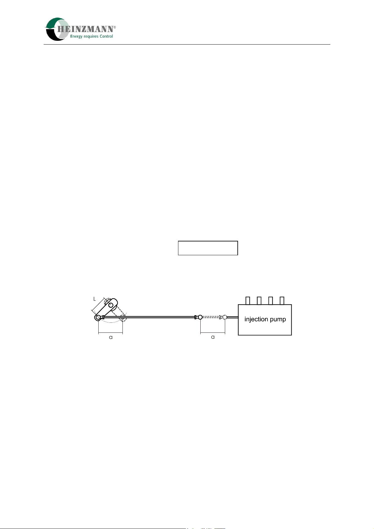
4.2.1 Length of Lever Arm
The length “L” of the lever arm is determined in such a way that approx. 90 % of the
governor output shaft adjustment angle can be used. Based on this, “L” for governors with
90° adjustment angle is calculated as:
with "a" being the travel distance of the injection pump or the carburettor.
Figure 5: Length of Lever Arm
4.2.2 Connecting Linkage
The connecting linkage from the governor to the injection pump or the carburettor should
be length-adjustable and have a (pressure or tension) elastic link. If the actuators torque is
less than 10 Nm, the elastic link is not needed. If possible, joint rod heads in accordance
with DIN 648 should be used as connecting links. The linkage must operate easily and
without clearance.
In case of friction or backlash in the linkage connecting actuator and injection pump resp.
throttle valve no optimal control is possible.
L ~ 0.75 · a

4 Regulating Linkage
4.2.3 Linkage Adjustment for Diesel Engines
The length of the connecting linkage is adjusted in such a way that with the governor in
stop position the injection pump is set to 0 - 2 fuel marks. (Travel of the injection pump
control rack is limited by the governor.)
Figure 6: Example of linkage for diesel engines
The resistance of the pressure elastic link is overcome when the control rack has reached
the full load stop and the speed continues to decrease (overload). Furthermore, the elastic
link is overcome when stopping via the emergency switch.
Full load position
Stop
Elastic link
Idle position

4 Regulating Linkage
4.2.4 Linkage Adjustment for Carburettor Engines
For carburettor or gas engines, the length of the connecting linkage is adjusted in such a
way that with the governor in full load position the throttle valve is completely open. In
idling speed position, the elastic link must be slightly overcome. This allows adjustment of
the idle screw without changing the governor adjustment.
Figure 7: Example of linkage for gas engines
If carburettor or injektion pump are to the left of the governor as opposed to their position
on the drawings, then the direction of motion of the elastic link must also be reversed.
Positioner
Throttle
valve
Stop screw
for idle speed
Idle position
Full load position
Elastic link

5 Electrical Connection
5Electrical Connection
5.1 Pin Assignment
A Power supply (+) 24 VDC
B Setpoint (+) 4 … 20 mA
C Setpoint (-) 0 VDC
D Power supply (-) 0 VDC
E Position value (+) 4 … 20 mA
F Position value (-) 0 VDC
G n.c.
Figure 8: Pin assignment of StG 40.90-09 PD
5.2 Connection of Power Supply
Inappropriate choice of power supply or insufficient battery capacitance or incorrect
connection of the power supply line or too small cable sizes of the feed line and the motor
line of the positioner are bound have an adverse effect upon the performance of the speed
governor. In steady state operation, this will cause a heavy increase of current consumption
and unnecessary vibration of the positioner drive. The high current consumption will in its
turn lead to overheating of the actuator or the position control unit, and the vibration will
result in premature wear of the gear and bearing parts or of the linkage.
In altogether, the lifetime of the control system is distinctly
reduced by the errors described above..
The following figure shows both a wrong and a correct cabling:
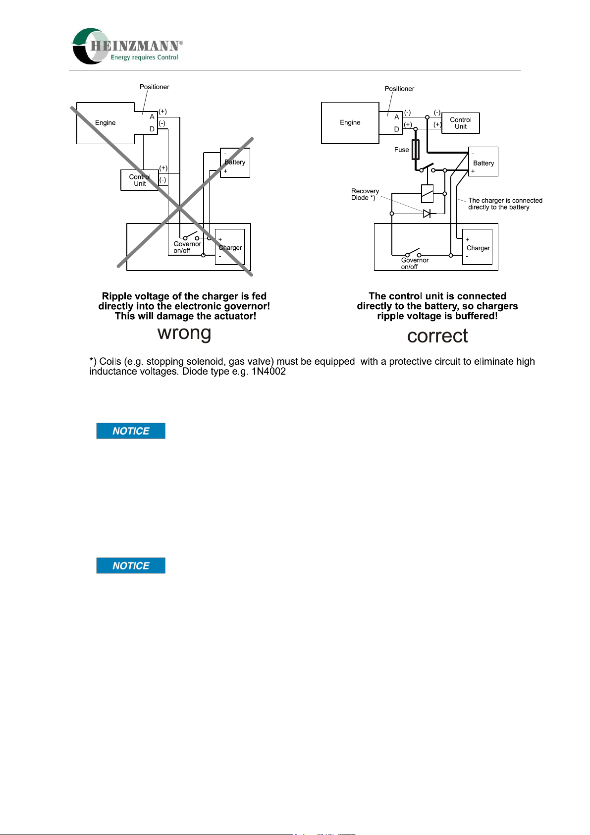
5 Electrical Connection
Figure 9: Correct Connection of Power Supply
If there are battery chargers with rapid charge mode installed in
the plant, the rapid charge mode should no be used during
operation.
If there is no battery provided, it is absolutely necessary that a three phase power supply or a
stabilized single phase power supply with at least 24 V DC, 10 Amps output power be used
as a power source.
The cable sizes and cable lengths described in the wiring
diagrams must not be exceeded!.
When power supply, battery and cabling have been correctly dimensioned, then on starting
the engine or with the positioner operating at maximum current consumption (approx.
6.4 A), a drop of the supply voltage directly at the control unit of approx. 2 Volts
maximum only will be admissible.

6 Figure List
6Figure List
Figure 1: Example for relation between current input signal and position................................ 5
Figure 2: Functional block diagram ........................................................................................... 6
Figure 3: Principle of StG 40.90-09 PD..................................................................................... 7
Figure 4: Dimensional drawing StG 40.90-09 PD ................................................................... 10
Figure 5: Length of Lever Arm................................................................................................ 11
Figure 6: Example of linkage for diesel engines...................................................................... 12
Figure 7: Example of linkage for gas engines.......................................................................... 13
Figure 8: Pin assignment of StG 40.90-09 PD......................................................................... 14
Figure 9: Correct Connection of Power Supply....................................................................... 15
Table of contents
Other Heinzmann Industrial Equipment manuals


Popular Industrial Equipment manuals by other brands


 user manual")


RenewAire
RenewAire HE Series Installation, operation and maintenance manual

STI
STI EZ-Path 33 Series Installation sheet

Dorner
Dorner 3200 Series Installation, maintenance & parts manual

SKYLUX
SKYLUX Polyprofil Mounting instructions

Trumpf
Trumpf PFO 33 Operator's manual

Viessmann
Viessmann 4519 Operation manual