Heise DXD Series User manual

1
Revision 1.6.1 2/28/06 Printed in USA
DXD Series - Precision Digital
Pressure Transducer
Installation and Operating Instructions
I&M 002-10106 DXD
Revision 1.6.1 2/28/06

2
Revision 1.6.1 2/28/06 Printed in USA

3
Revision 1.6.1 2/28/06 Printed in USA
Contents
Section 1.0 Introduction .................................................................................................................................. 5
Section 2.0 Cautions ....................................................................................................................................... 5
Section 3.0 Theory of Operation .................................................................................................................... 5
Section 4.0 Unpacking .................................................................................................................................... 5
4.1 DXD Transducer(s) .............................................................................................................................. 5
4.2 Certificate of Calibration ..................................................................................................................... 6
4.3 Utility Software .................................................................................................................................... 6
4.4 Accessories (RS232 Configurations only) ........................................................................................ 6
Figure 1. Modular Power Supply with RJ11/4 Connector ................................................................ 6
Figure 2. Serial Port Adapter Assembly ............................................................................................ 6
Section 5.0 Installation .................................................................................................................................... 7
5.1 Pressure Connections ........................................................................................................................ 7
5.2 System Wiring ..................................................................................................................................... 7
5.3 Installation Wiring for RS232 Systems with Accessory Kit .............................................................. 7
5.3.1 Pin Functions and Cable Fabrication for RS232 Compatible Systems .................................. 7
Table 1. Switchcraft EN3 Pin Assignments for RS232 Configuration. ...................................... 8
Table 2. ITT Cannon KPT03 Pin Assignments for RS232 Configuration. ................................. 8
Table 3. RJ11 Connector Functions for RS232 Systems ........................................................... 8
5.4 Wiring Installation for RS485 Systems .............................................................................................. 9
5.4.1 Pin Functions and Cable Fabrication for RS485 Compatible Systems .................................. 9
Table 4. Switchcraft EN3 Pin Assignments for RS485 Configuration ....................................... 9
Table 5. ITT Cannon - KPT03 Pin Assignments for RS485 Operation ...................................... 9
Section 6.0 Installing and Running Utility Software ................................................................................... 10
Section 7.0 Using HyperTerminal with the DXD .......................................................................................... 10
7.1 Configuring HyperTerminal .............................................................................................................. 10
7.2 Basic Communications with the DXD .............................................................................................. 10
7.2.1 Communication and Command Basics ................................................................................. 11
7.3 Launching the Previously Configured .................................................................................................
HyperTerminal Application ............................................................................................................... 11
7.4 Talking to the DXD with HyperTerminal .......................................................................................... 11
7.4.1 Determine and Set the Current Address ................................................................................ 11
7.4.2 Determine and Set Baud Rate ................................................................................................. 11
7.4.3 Determine the Pressure Type .................................................................................................. 12
7.4.4 Determine the Full Scale Pressure Range ............................................................................. 12
7.4.5 Get a Pressure Reading .......................................................................................................... 12
7.4.6 Get the Heise Label ................................................................................................................. 12
7.4.7 Get and Change the Current User Label ................................................................................ 13
7.4.8 Get and Change the Current User Tare Value ........................................................................ 13
Section 8.0 Field Calibration ......................................................................................................................... 14
8.1 Zero Adjustment ................................................................................................................................ 14
8.2 Span Adjustment ............................................................................................................................... 14

4
Revision 1.6.1 2/28/06 Printed in USA
Section 9.0 DXD Command Library .............................................................................................................. 15
9.1 Communications Settings ................................................................................................................ 15
9.2 Communications Protocol ................................................................................................................ 15
9.3 Command Library Mnemonics ......................................................................................................... 16
ERROR CODES ................................................................................................................................. 20
Section 10.0 DXD Command Summary ....................................................................................................... 21
10.1 Read Command Summary .............................................................................................................. 21
10.2 Write Command Summary ............................................................................................................. 21
10.3 Error Code Summary ...................................................................................................................... 21
Section 11.0 DXD Product Specification ...................................................................................................... 22
Appendix A- Resolution by Pressure Range .............................................................................................. 23
Appendix B - System Performace Response Time ..................................................................................... 24
Appendix C - RS485 System Schematic ...................................................................................................... 25
Index .............................................................................................................................................. 27
Appendix D - Warranty and Limitation of Liability ...................................................................................... 30
Trademark Credits
Windows is a registered trademark of the Microsoft Corporation.
Windows 95 is a registered trademark of the Microsoft Corporation.
Windows NT is a registered trademark of the Microsoft Corporation.
Visual Basic is a registered trademark of the Microsoft Corporation.
Active X is a registered trademark of the Microsoft Corporation.
Hyperterminal is a registered trademark of Microsoft Corporation
LabVIEW is a registered trademark of National Instruments.

5
Revision 1.6.1 2/28/06 Printed in USA
Section 1.0 Introduction
Congratulations on your purchase of a DXD Series
Digital Pressure Transducer. This transducer provides
unmatched performance and value. Innovative
modeling and processing firmware assures extremely
high precision over a broad temperature range as well
as extremely fast response. Please read the follow-
ing cautions and instructions carefully in order to take
full advantage of the product’s capabilities.
Section 2.0 Cautions
Pressure instruments must be selected in accordance
with industry codes and safety practices to avoid the
possibility of misuse or misapplication, which could
result in personal injury or property damage. Person-
nel responsible for selection and installation should
also be familiar with the safety recommendations of
ASME B40.1, that apply to elastic pressure elements
and their application in general and specific services.
ASME B40.1 is available from:
ASME
345 47th Street
New York, NY 10017
• Select a range so that the maximum applied
pressure will never exceed the upper range limit.
• Excessive vibration could cause loosening of
components resulting in loss of instrument
accuracy or failure to provide valid data.
• Excessive pressure pulsation could result in
fatigue failure of the pressure element.
• Operation of the instrument in an environment
where temperatures are in excess of design
ratings may result in loss of accuracy and
failure.
• Pressure boundary materials must be resistant
to the process media. Failure to assure compat-
ibility may result in pressure sensing element
deterioration or failure. Instruments used on
high-pressure gas, or potentially hazardous
service, such as oxygen should be carefully
selected in accordance with the recommenda-
tions of ASME B40.1.
• Only approved explosion proof or intrinsically
safe instruments should be used in hazardous
locations.
•Instruments used in locations where EMI/RFI
conditions exist may exhibit erroneous perfor-
mance.
• These instruments are not explosion proof or
intrinsically safe. Power levels present preclude
use in hazardous locations.
Section 3.0 Theory of Operation
The DXD transducer design employs a piezo resistive
strain gauge, a 24 bit A/D converter, microprocessor
and a 20 MHz clock. The A/D resolution is internally
reduced to 50,000 counts to optimize signal to noise
ratio. The raw data is processed with a proprietary
algorithm which employs a fourth order polynomial.
The math package fits both temperature and pres-
sure signals from the transducer using coefficients
calculated from the outputs of pressure and tempera-
ture standards during the calibration process. The
internal update rate can be set to 27.7mS or 12.6 mS.
The DXD responds to a simple ASCII command
protocol. The total transmit/ receive time for fully
corrected pressure data is 30 mS (when set to 27.7
mS) and 15 mS (when set to 12.6 mS) at 115,200
bps. There may be a slight reduction in signal stability
(1 to 3 counts) when operated at 15 mS as the
difference in signal processing time is gained at the
expense of filtering in the processor. The firmware
supports addressable, multi-drop operation. Electrical
communications are via full duplex RS232 or RS485
standards. The maximum resolution is 50,000 counts.
Section 4.0 Unpacking
Please note: When handling connectors care should
be taken to avoid electrostatic discharge to prevent
damage to the electronics. The power pins are
reverse polarity protected. Use caution if fabricating
connector and cable assemblies because the digital I/
O lines are not protected from the inadvertent appli-
cation of power. Following is a description of material
included in shipment.
4.1 DXD Transducer(s)
The DXD is available in a variety of standard pressure
ranges and types as specified at time of order
placement. It is configured for either RS232 or
RS485 operation at the factory as specified at
time of purchase. The output is not field
configurable. Please check the product label to
ensure that the pressure range and output signal type
are correct.
6
Revision 1.6.1 2/28/06 Printed in USA
4.2 Certificate of Calibration
Each DXD is provided with a report of calibration
traceable to NIST. The report is packaged with the
transducer.
4.3 Utility Software
Software is provided on three 3 1/2-inch disks or CD
rom. The Windows compatible software simplifies the
setup and installation of the DXD. It also provides
powerful data logging and pressure display capabili-
ties. It includes an “.OCX” compatible com driver
which can be utilized through Active X compliant
software.
4.4 Accessories (RS232 Configurations only)
The following accessory items are available individu-
ally or in kit form at time of order. These accessories
are designed for use with the RS232 version of the
product. The DXD with complete kit option includes
the following items:
4.41 Modular power supply. The AC Adapter
supplies 12 VDC power (500 mA) to the Serial Port
Converter and the DXD transducer(s) which are
interconnected forming a “network”. The DXD has its
own regulated power supply (internal DC to DC
converter) and is protected against spikes and supply
reversals. Each DXD consumes approximately 300
milliwatts or 15ma at 20 volts. The power supply can
be plugged in anywhere along the network, it does not
have to be near the Serial Port Converter. The
contact rating of the RJ11/4 (telephone-type) connec-
tor is 1.5 amps which provides a fast, economical,
and reliable method of interconnection.
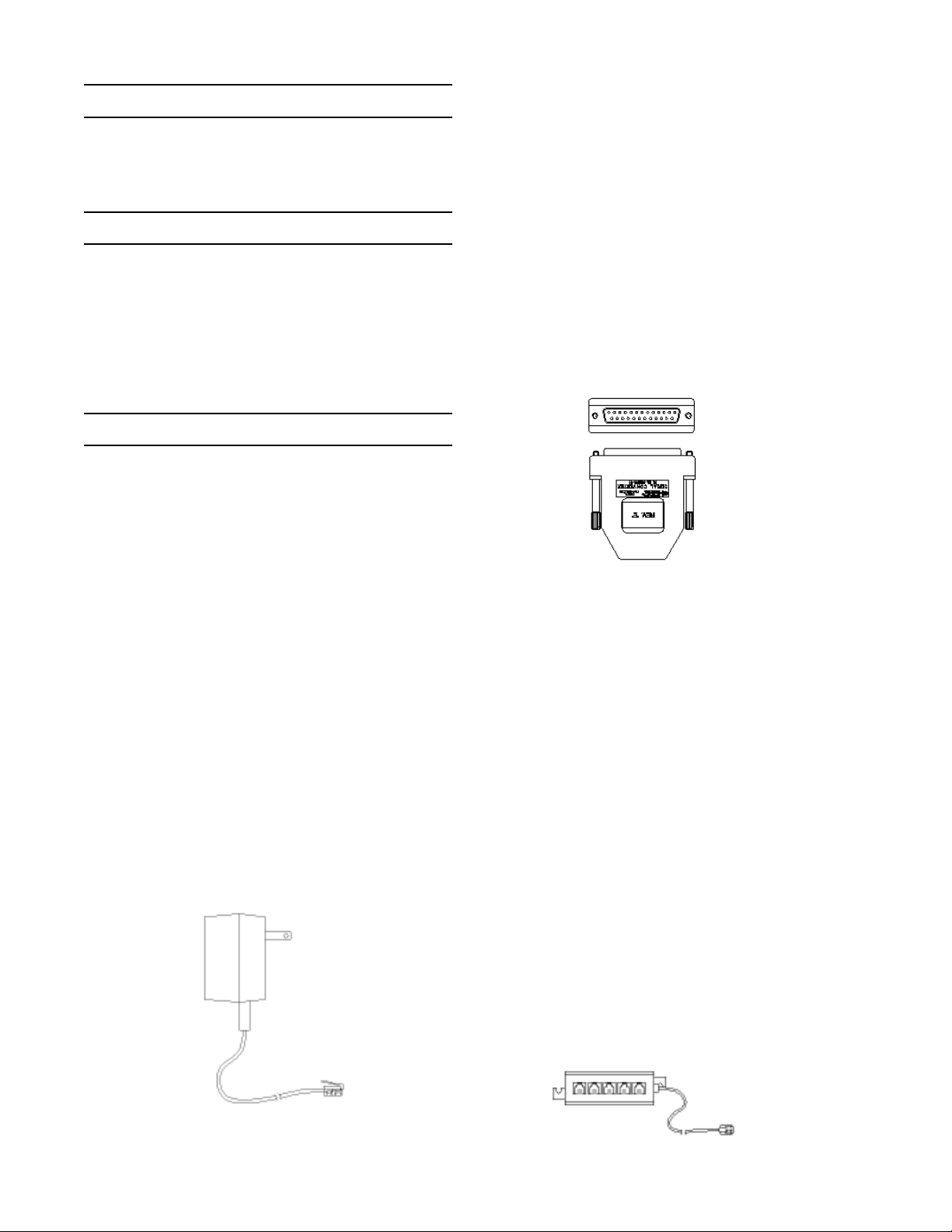
Figure 1. Modular Power Supply with RJ11/4
Connector
4.42 Serial port converter. The Serial port converter
consists of electronics housed in a standard DB25
connector’s shell assembly. It has a standard DB25
female RS-232C socket on one end and two RJ11/4
jacks on the other. The DB25 side plugs into an RS-
232C port and the RJ11/4 jack connects to the
transducer(s). Its function is to amplify and buffer
standard RS-232C signals so that up to 99 DXD
transducers can be connected in parallel in any
configuration, Daisy Chain or Star. One converter is
required per 99 units. The converter can drive exten-
sion cables up to 1000 feet (total cable length) and
still maintain data integrity while communicating at
high speed with each transducer.
Figure 2. Serial Port Adapter Assembly
4.43 25 to 9 pin adapter. A25 pin to nine pin adapter
is provided to facilitate connecting the serial port
converter’s DB25 pin connector to a computer or
terminal serial port having a DB9 pin connector.
4.44 25 foot cable. The 25-foot cable connects the
DXD to an expander module or directly to a serial port
converter. The cable is provided with a Switchcraft or
Cannon connector on one end and an RJ11/4 (tele-
phone-type plug) on the other. Pushing the female
connector onto the male socket and then securing the
connector with the sleeve by turning the sleeve until it
locks in place makes connection to the DXD.
4.45 Five-port expander module. Afive-port ex-
pander module consists of a block with five female
RJ11/4 jacks and a six-inch pigtail with a male RJ11/4
connector. The DXD cable plug(s) and the modular
power supply plug are inserted into the available
jacks and the male plug on the pigtail of the five port
expander is inserted into the female jack on the serial
port converter.
Figure 3. Five-Port Expander Module
7
Revision 1.6.1 2/28/06 Printed in USA
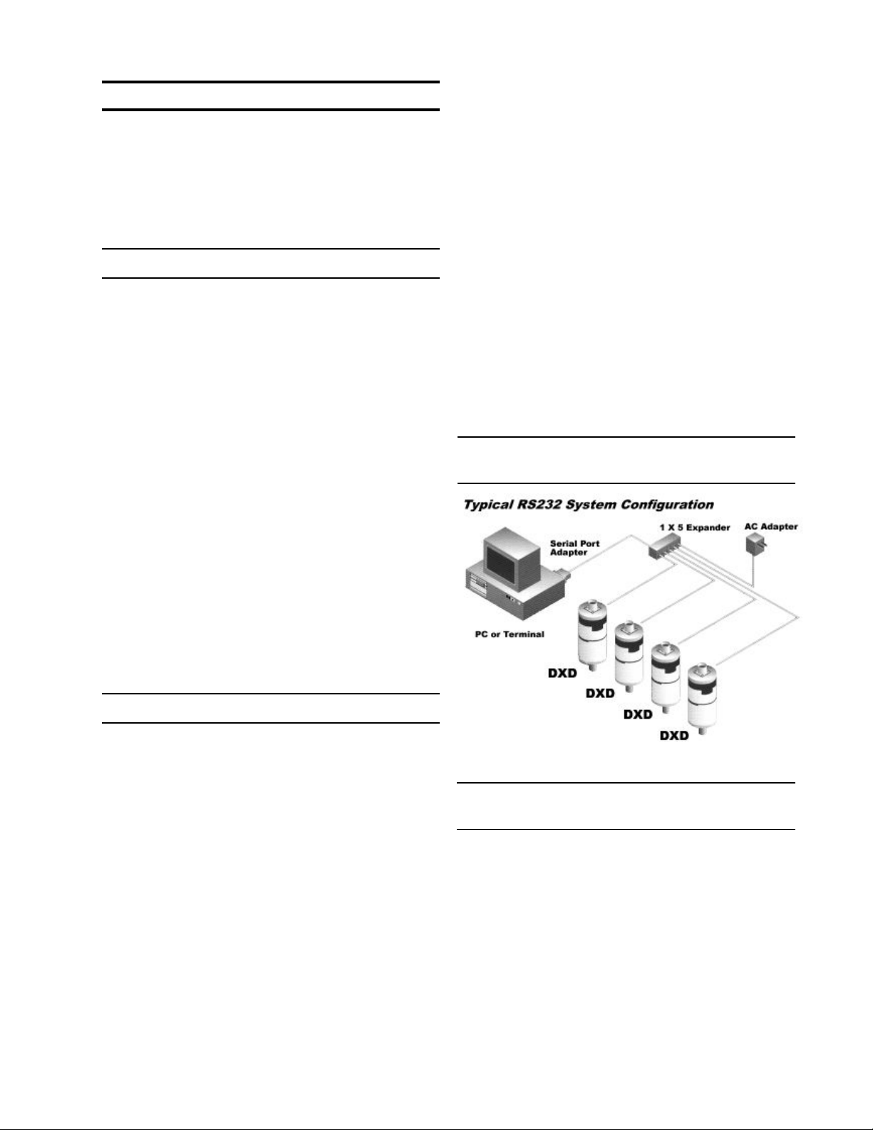
Section 5.0 Installation
The Installation of the product has three basic steps,
which include making pressure connections, system
wiring (connecting communication and power cables
to the transducers and a PC or PLC and installing and
running software to communicate with and set up the
DXD transducer.
5.1 Pressure Connections
The standard pressure inlet fitting is a 1/4 inch NPTM
type connector unless an optional fitting was specified
at time of purchase.
IMPORTANT NOTE: The standard vented housing is
recommended for gauge pressure types with ranges
less than or equal to 500 PSI. This is because
changes in ambient temperature will increase or
decrease the pressure of the gas volume within the
housing producing an undesirable effect on the
performance of the unit. The housing is vented
through the Switchcraft or Cannon electrical connec-
tor by removal of one of the unused connector pins at
the factory (see Table 1 and 2). Asealed housing (no
connector pin removed) can be specified at time of
purchase if required. The effect is approximately
±0.027 PSI per degree Fahrenheit change in ambient
temperature.
This is not a factor on absolute pressure ranges
because the reference side of the sensor is
evacuated and sealed.
5.2 System Wiring
5.2.1 RS232 Cables. The RS232 configuration
requires four conductors for signal in, signal out,
power positive, and power negative. Prefabricated
telephone type cables with RJ11 modular connectors
and Switchcraft or ITT Cannon connectors can be
purchased from the factory as a kit for RS232 con-
figurations. Other cable and connector combinations
can be fabricated using user supplied, multiconductor
wire and connectors per the following pin function
tables. Minimum 26 AWG wire is recommended.
5.2.2 RS485 Cables.The RS485 configuration
requires six conductors two for signal in, two for
signal out, one for power positive, and one for power
negative. The user can fabricate similar telephone
type cable and modular connectors for RS485
configurations. This configuration uses eight conduc-
tor RJ45 plugs and sockets and cable such as Alpha
9314C 24 AWG. Other cables and connector combi-
nations can be fabricated using user supplied,
multiconductor wire and connectors. Minimum 26
AWG wire is recommended.
5.2.3 Cable length and transmission speed. Total
cable length, wire gage and total number of transduc-
ers connected to the system have an effect on
maximum communication speed. This is due to the
effects of cumulative resistance and capacitance on
the signals. The tables in appendix B illustrate the
relationship between cable length, number of DXD
transducers and communication speed.
5.2.4 Transducer Connectors. The DXD is available
with a standard Switchcraft EN3 electrical connector
or an optional ITT Cannon KPT03 (Bendix PTX
compatible) electrical connector. Both configurations
operate in full duplex (simultaneous send and re-
ceive) mode.
5.3 Installation Wiring for RS232 Systems with
Accessory Kit
5.3.1 Pin Functions and Cable Fabrication for
RS232 Compatible Systems
The following information is provided for reference if
you wish to fabricate your own cables. The Switch-
craft EN3 connector has eight pins. The RS232
configuration utilizes four pins with the following
assignments and functions:

8
Revision 1.6.1 2/28/06 Printed in USA
Table 1. Switchcraft EN3 Pin Assignments for
RS232 Configuration.
Table 3. RJ11 Connector Functions for RS232
Systems
Table 2. ITT Cannon KPT03 Pin Assignments for
RS232 Configuration.
DXD Definition Host Destination
Digital Output
Digital Input

9
Revision 1.6.1 2/28/06 Printed in USA
5.4 Wiring Installation for RS485 Systems
Required Equipment
RS485 card. Afull duplex RS485 card is required for
setting up an RS485 system. This type of card is
available from a wide variety of manufactures.
Factory experience is limited to National Instruments
P/N AT485/2 although any fully compliant card should
work. An RS485 system can also be connected to a
standard RS232 port using a powered RS232 to 485
adapter such as those supplied by Black Box (model
485PS).
Power supply. ADC power supply capable of
providing 12 to 24 VDC and 15mA per transducer is
required.
Wiring: According to the RS485 standard six con-
ductor, shielded, twisted pair 24 AWG is recom-
mended for interconnecting RS485 systems. How-
ever, modular telephone cable and hardware (RJ45
six conductor) can be employed depending on the
application (distance, EMI, RFI, speed). Daisy chain
interconnection is recommended with minimum drop
lengths. See RS485 schematic, appendix C.
5.4.1 Pin Functions and Cable Fabrication for
RS485 Compatible Systems
Connectors: The DXD is supplied with either
Switchcraft or Cannon (Bendix Compatible) connec-
tors as specified at time of purchase. The pin identifi-
cation and assignments are shown in Tables 4 and 5.
Table 4. Switchcraft EN3 Pin Assignments for
RS485 Configuration
Table 5. ITT Cannon - Bendix Compatible Pin
Assignments for RS485 Operation

10
Revision 1.6.1 2/28/06 Printed in USA
Section 6.0 Installing and Running Utility Soft-
ware
Computer Requirements.A Pentium class PC is
recommended to take full advantage of the high
speed capabilities of the DXD digital pressure trans-
ducer, however, any PC capable of running Windows
95 can be used.
Software. Three Disks and/or a CD rom are available
for the DXD transducer that provide a program called
DXDSetup. This optional software provides an easy
means of setting up the user configurable features of
the DXD along with data logging and display capabili-
ties. It includes an “OCX” compatible com driver
which can be utilized through Active X compliant
software. See the software supplement for details.
Section 7.0 Using Hyperterminal with the DXD
Windows 95 includes a utility terminal emulation
program called Hyperterminal. Hyperterminal can be
used to communicate with the DXD in order to setup
user preferences such as address, label, etc. and to
read pressure. The following section will guide you
through the steps required to accomplish this. This
tutorial in DXD command structure can also be used
with the Windows 3.1 Terminal.exe application or any
terminal emulation software provided you are familiar
with the setup characteristics of those programs. The
command syntax illustrated in the following section
will familiarize you with how they are implemented if
you wish to write your own software.
Basic Setup Information
Each DXD transducer is configured for address value
01 and bit rate 19,200 bits per second as shipped
from the factory. These values can be changed,
however, the following instructions assume that you
are using the DXD in the factory configuration.
Signal and Power Connections
Make all electrical and power connections as de-
scribed in Section 5.0. IMPORTANT:Be sure to
connect only one DXD until you are familiar with
its addressing conventions.
7.1 Configuring HyperTerminal
The Hyperterminal application prompts you through
the process of setting up communication parameters
that include assigning a file name and icon and
setting the com port, data format, bps (bit per sec-
ond). After this is done, you can save the configura-
tion using a name like “DXD” and simply open it by
name without need to re-configure it each time it is
used. This application will work with RS232 ports,
RS232 ports with a RS232 to RS485 adapter, or an
RS485 port.
1. Click the start button on the task bar and drag up to
Run...
2. Type hypertrm in the text box and click OK. This
will launch the Hyperterminal configuration program.
3. You will be prompted for a name so use something
easy to remember like DXD. Type the name and
select an icon. Click on the OK button.
4. The next box will prompt you for a phone number.
Pull down the Connect using: box and choose the
appropriate com port and click OK (a phone number
isn’t utilized in this type of setup).
5. Next you will be prompted for com port setup which
should be configured as follows: Bits per second:
19200, Data bits: 7, Parity: Even, Stop bits: 1, Flow
control: None.
6. Next click on the settings tab and click on ASCII
setup button.
7. Click in the check boxes labeled Send line ends
with line feeds and Echo typed characters locally.
Click OK to close this box and OK to close the next
box.
8. You have now configured HyperTerminal to com-
municate with the DXD. Open the File drop box in the
upper left hand corner of the window and select save.
This will save the com port configuration for later use.
9. Open the File drop box in the upper left hand
corner of the HyperTerminal window and select Exit.
You will be prompted by an alert message stating that
you are currently connected and asking if you want to
terminate now. Click Yes and HyperTerminal will
close.
7.2 Basic Communications with the DXD
The command library in Section 9 contains a detailed
description of all of the DXD commands, responses
and data formats. It also outlines the command
syntax required to read from or write to the DXD. The
following section describes how to use these com-
mands via HyperTerminal.

11
Revision 1.6.1 2/28/06 Printed in USA
7.2.1 Communication and Command Basics
There are some basic conventions and characteris-
tics which must be observed in order to communicate
with the DXD.
• The data format is 7 data bits, 1 stop bit, even
parity
• All commands are prefaced with the pound sign
character (#, ASCII 35) which serves as an
attention character.
• All responses are alphanumeric and include a
carriage return (CR) and line feed (LF) ASCII 13
and 10.
• The pound sign is followed by a two character
numeric address (01 through 99). Note that with
one DXD connected you can substitute a double
asterisk (*, ASCII 42) if you don’t know the
current address value.
• The DXD has two categories of commands which
are read (get data from) or write (send data to)
the DXD. All read commands are issued as
uppercase characters and corresponding write
commands are issued using lower case charac-
ters followed by the data to be written.
• The format of data used in write commands is
critical so please review the command library if
you encounter problems in the following section.
• NOTE: The [CR] in the following examples means
hit the enter key. Acarriage return (ASCII13) is
required to terminate a read or write command.
7.3 Launching the Previously Configured
HyperTerminal Application
1. Ensure that only one DXD is connected to the
computer and that power is applied.
2. Click the Start button on the task bar, select
programs, then accessories and then click on
HyperTerminal. This will open a folder on the desk top
that contains the HyperTerminal setup you created in
the preceding section. Double click the file icon to
launch HyperTerminal. When the program opens it
will be properly configured to communicate with the
DXD set to its factory defaults.
7.4 Talking to the DXD with HyperTerminal
7.4.1 Determine and Set the Current Address
The value retrieved with the AD (Address) command
is comprised of 7 alphanumeric characters (including
CR/LF) that can be modified by the user to set a
desired address value. The address value of the DXD
is user configurable and the default factory value is
01.
Note: There may be circumstances where the ad-
dress is unknown. To simplify the task of determining
the current address setting, the DXD can recognize a
“wild card” value comprised of double asterisks (**).
Substitute it in the address position of a read com-
mand. For example, #01AD can be sent as #**AD
(provided only one DXD is connected to the system).
1. To determine the DXD’s current address type the
following command:
#**AD[CR]
2. The DXD will respond with the following message:
AD=01 indicating that the address is currently
configured to the value 01.
3. To change the DXD’s address from 01 to 02 type
the following command:
#01ad02[CR]
4. To verify that the address has been changed, send
the following command:
#**AD[CR]
5. The DXD will respond with the following message:
AD=02
6. To change the DXD’s address back to 01 type the
following command:
#01ad01[CR]
7. To verify that the address has been changed, type
the following command:
#01AD[CR]
8. The DXD will respond with the following message:
AD=01
7.4.2 Determine and Set Baud Rate
The value retrieved with the BR (Baud Rate) com-
mand is comprised of 11 alphanumeric characters
(including CR/LF) which can be modified by the user
to set the desired system baud rate.
1. To read the current baud rate, type the following

12
Revision 1.6.1 2/28/06 Printed in USA
command in the HyperTerminal window:
#01BR[CR]
2. The DXD will respond with the following message:
BR= 19200
3. To change the current baud rate you first must
change the DXD’s setting then change the com port
setting for HyperTerminal. To change the DXD baud
rate from 19200 to 9600, type the following com-
mand:
#01br= 9600[CR]
4. You will be unable to communicate with the DXD
until the com port settings are changed in
HyperTerminal.
5. To do this click the File button and select Proper-
ties. Click on “Configure” then click the arrow box
next to Bits per Second then select 9600. Click OK
for the com properties box and OK for the file proper-
ties box.
6. Next click on the Call button and select Disconnect
then Connect (this activates any changes made to
HyperTerminal’s communications properties).
7. To read the revised baud rate, type the following
command:
#01BR[CR]
8. The DXD will respond with the following message:
BR= 9600
9. To change the baud rate back to 19200 type the
following command:
#01br=19200[CR]
10. Remember that you will be unable to communi-
cate with the DXD until the com port settings are
changed in HyperTerminal.
11. To do this click the File button and select Proper-
ties. Click on “Configure” then click the arrow box
next to Bits per Second then select 19200. Click OK
for the com properties box and OK for the file proper-
ties box.
12. Next click on the Call button and select Discon-
nect then Connect (this activates any changes made
to HyperTerminal’s communications properties).
13. To read the revised baud rate, type the following
command:
#01BR[CR]
14. The DXD will respond with the following message:
BR= 19200
7.4.3 Determine the Pressure Type
1. The value retrieved with the PT (Pressure Type)
command is the pressure type of the unit. It is com-
prised of 6 alpha numeric characters (including CR/
LF) and specifies the pressure type of the transducer.
It is assigned during manufacturing and can not be
changed. To read the pressure type (gauge, absolute,
vacuum, compound), type the following command:
#01PT [CR]
2. The DXD will respond by transmitting the following
message to the Hyper Terminal window.
PT=G (G for Gauge, Afor absolute, Vfor vacuum, C for
compound)
7.4.4 Determine the Full Scale Pressure Range
1. The value retrieved with the FS (Full Scale) com-
mand is the fullscale pressure range of the unit. It is
comprised of 13 alpha numeric characters (including
CR/LF) and specifies the pressure range of the
transducer. It is assigned during manufacturing and
can not be changed. To read the current FS value,
type the following command in the Hyper Terminal
window:
#01FS [CR]
2. The DXD will respond by transmitting the following
message to the Hyper Terminal window.
FS=+030.000 (Note that the decimal position is range
dependent see Appendix Afor details)
7.4.5 Get a Pressure Reading
1. To read the current pressure in PSI, type the
following command in the Hyper Terminal window:
#01PS [CR] (or #**PS[CR])
2. The DXD will respond by transmitting the following
message to the Hyper Terminal window.
PS=+000.000 (or the value of the existing pressure)
7.4.6 Get the Heise Label
1. The value retrieved with the HL (Heise Label)
command is the serial number assigned to the unit
during manufacturing and can not be changed. To
read the value stored in the HL location, type the
following command:
#01HL[CR]

13
Revision 1.6.1 2/28/06 Printed in USA
2. The DXD will respond by transmitting the following
message:
HL=000XXX (where X represents your DXD’s actual
serial number )
7.4.7 Get and Change the Current User Label
1. The value retrieved with the UL (User Label)
command is comprised of up to 16 alphanumeric
characters which can be modified by the user to form
a descriptive tag or identification name. To read the
current user label value, type the following command:
#01UL[CR]
2. The DXD will respond by transmitting the following
message:
UL=User Label Here (this is the factory default value)
3. To change the current user label to “Test Point 01”,
type the following command:
#01ulTest Point 01[CR]
7.4.8 Get and Change the Current User Tare Value
1. The value retrieved with the UT (User Tare) com-
mand is comprised of 11 alphanumeric characters
which can be modified by the user to remove or “tare
out” a pressure preload from the displayed pressure
value. To read the current user tare value, type the
following command:
#01UT[CR]
2. The DXD will respond by transmitting the following
message:
UT=+000.000 (note: This is the factory default value
and that the decimal position will depend on the full
scale range of the unit)
3. To change the current user tare to 1 PSI, type the
following command:
#01ut+001.000[CR]

14
Revision 1.6.1 2/28/06 Printed in USA
Section 8.0 Field Calibration
Calibration adjustments on the DXD are limited to
adjusting zero and span. Ahigh precision primary
standard (50 ppm or better) is required for the span
adjustment on gauge, vacuum and compound
pressure types and a precision absolute standard is
required for absolute pressure types
8.1 Zero Adjustment
1. Zero adjustment. This example will guide you
through the process of adjusting zero for a gauge,
compound or vacuum pressure type unit. Absolute
pressure types require that you connect the DXD to a
vacuum source capable of achieving 0.05 torr for
ranges from 15 to 50 PSIA or .5 torr for ranges from
60 to 500 PSIA.
2. Be sure that the DXD is at zero pressure (vented to
atmosphere for gauge, vacuum or compound pres-
sure types) or full vacuum for absolute pressure
types.
3. Send the following command: #01uz+000.000[CR].
This will reset the user zero offset value to zero.
4. Send the following command: #01PS and note the
result which will be something like PS=+000.002
5. Send the opposite sign of the PS value received in
step 4 above (-000.002) with the following command:
#01uz-000.002 [CR]
6. Confirm that the zero adjustment is complete by
sending the following command:
#01PS[CR] which should result in a display of
PS=+000.000
8.2 Span Adjustment
1. This procedure requires a primary pressure
standard of suitable accuracy. The following example
is based on a DXD with a full span rating of 30 PSI.
The value that will be adjusted is US (user span).
2. The first step is to connect the transducer to a
pressure standard and apply full span pressure (30
PSI in this example).
3. Next, retrieve the current pressure reading by
sending the following command:
#01PS[CR]
4. The result will be something like this: PS=+030.002
5. Next retrieve the current value of user span (US)
by sending the following command: #01US[CR]
6. Next calculate the new value for US by dividing the
known pressure generated with the pressure stan-
dard by the displayed value, for example, 30/
30.002=0.99993.
7. Multiply the current US value retrieved in step 5 by
0.99993 to calculate the new US value.
8. To write the new US value to the DXD, send the
following command:
#01uz+0.99993[CR]
9. Confirm that the span has been properly adjusted
by applying full span pressure and retrieving the
current pressure reading with the following command:
#01PS[CR]
10. The result should be PS=+030.000 (± 0.005% of
full span). If not, repeat steps 3 through 9 as required.

15
Revision 1.6.1 2/28/06 Printed in USA
Section 9.0 DXD Command Library
The DXD digital pressure transducer employs a simple ASCII character based protocol for communications.
ADXD UNIT cannot initiate this communication process. Ahost device, i.e. a computer, terminal or PLC
device must be used to initiate communications by querying the DXD. Multiple DXD’s on the same
communication bus are addressed sequentially so each unit must have a unique, two digit address between
01 and 99.
For applications where only one DXD is on the communications bus, wildcard characters “**” (double
astericks) can be used to address a single unit. Note: When using wildcard addressing for
communications care should be taken to ensure only one unit is being addressed. To avoid
problems that may arise from it’s use, wildcard addressing should be used primarily for testing or
troubleshooting purposes.
Commands issued to a DXD UNIT can be classified as one of two types.
1. Read Commands: These always return a value
2. Write Commands: Normally do not return a value, however, if the command issued syntax is incorrect an
error code value will be returned (see error codes section 9.3).
9.1 Communications Settings
The DXD Transducer uses the following communications settings
Bits Per Second Rates: 1200, 2400, 4800, 9600, 19200, 38400, 57600, 115200
Data Bits: 7
Stop Bits: 1
Parity: Even
Flow Control: None
9.2 Communications Protocol
9.21 Read Commands
Each read command is initiated with a pound sign (#, ASCII 35). Following the pound sign is a two character
numeric address (from 01 to99). The address is followed by a two character, upper case alpha command
mnemonic representing the command being issued. Acarriage return (ASCII 13) is used to terminate the
command.
9.22 Write Commands
Each write command is initiated with a pound sign (#, ASCII 35). Following the pound sign is a two character
numeric address (from 01 to99). The address is followed by a two character, lower case alpha command
mnemonic representing the command being issued. Following the mnemonic is the value to be written. A
carriage return (ASCII 13) is used to terminate the command. there is usually an input value to set.
Start DXD Address Command Input Value Termination
Character Mnemonic (for write only) Character
#01 through 99 2 Character Alpha Alphanumeric CR
Example 1. Read pressure command: #01PS[CR]
This command is directed to DXD UNIT address ‘01’ and a PSI pressure reading is being requested.
Example 2. Write Command: #01ulUNIT 100[CR]
This command is directed to DXD UNIT address ‘01’ and it’s User Label is being set to UNIT 100.

16
Revision 1.6.1 2/28/06 Printed in USA
9.3 Command Library Mnemonics
The same command mnemonic is used for both read and write functions. The destinction between read and
write commands is that read commands use uppercase characters and all write commands use lowercase
characters.
AD UNIT ADDRESS
Command Description: Reads or writes the DXD Unit’s address (valid address values are from 01 through
99)
Command Type :Dual (READ/WRITE) Command
Read Command Syntax: #01AD[CR]
Typical Read Command Response: The DXD transmits the address as a 7-Character string as shown below.
Char. Position 1 2 3 4 5 6 7
Response Char AD=0 1 CR LF
Write Command Syntax: #01ad03[CR]
Typical Write Command Response: None
BR BAUD RATE
Command Description: Reads or writes the DXD Unit’s Bits Per Second Rate. Valid Baud Rate values
include: 1200, 2400, 4800, 9600, 19200, 38400, 57600, 115200
Command Type :Dual (READ/WRITE) Command
Read Command Syntax: #01BR[CR]
Typical Read Command Response: The DXD transmits the Bits Per Second Rate as a 11-Character string as
shown below.
Char. Position 1 2 3 4 5 6 7 8 9 10 11
Response Char.BR=9 6 0 0 CR LF
Write Command Syntax #01br38400[CR]
Typical Write Command Response: None
ED EEPROM MEMORYMAP DUMP
Command Description: Returns the first 160 bytes of EEProm memory as decimal values. The values
returned are formatted 16 bytes per line with carriage return/line feeds appended at
ends.
Command Type: READ Command
Read Command Syntax: #01ED[CR]
Typical Read Command Response: Each line contains 65 characters including CR/LF.
005 000 000 000 000 001 000 000 000 000 000 000 000 000 003 006[CR][LF]
003 000 000 032 000 000 128 000 000 089 000 000 000 000 000 007[CR][LF]
003 000 000 064 002 000 128 000 000 089 000 000 000 000 000 007[CR][LF]
000 000 000 000 000 000 000 000 000 000 000 000 000 000 000 025[CR][LF]
000 000 000 000 000 000 000 016 000 000 000 000 000 000 000 000[CR][LF]
000 000 000 000 000 000 000 000 000 000 000 000 000 000 000 000[CR][LF]
000 000 000 000 000 000 000 000 000 000 000 000 000 000 000 000[CR][LF]
000 000 000 000 000 001 000 000 000 000 039 016 002 000 000 093[CR][LF]
000 000 000 000 000 000 000 000 000 000 000 000 000 000 000 000[CR][LF]
000 000 000 000 000 000 000 000 000 000 000 000 000 000 000 000[CR][LF]

17
Revision 1.6.1 2/28/06 Printed in USA
ER READ FROM EEPROM ADDRESS
Command Description: Returns a specified EEProm location’s value in decimal format, as a 3 digit value
ranging from 000 to 255.
Command Type: READ Only Command
Read Command Syntax: #01ER005[CR] ……Read from EE location 005
Typical Read Command Response: Displays the EEPROM location contents as a 5-character string as
shown below:
Char. Position 1 2 3 4 5
Response Char.0 0 1 CR LF
EW WRITE TO EEPROM ADDRESS
Command Description: Writes a value to the current EEProm address. The current EEProm address is set
using the ER command above. To change an EEProm address content the ER and
EW commands must be used in conjunction with each other. The ew command sets
a flag to cause the pressure and temperature coefficients to be reloaded from the
EEPROM to RAM.
Command Type: Write Only Command
Write Command Syntax: #01ew005[CR] ……Write “005”, to current EE location.
Typical Write Command Response: Echoes back the characters written as 5-character string shown below.
Char. Position 1 2 3 4 5
Response Char.0 0 5 CR LF
IMPORTANT NOTE: This command echoes back the characters written. This is the only write command that
always sends back a response. All other write commands only send back a response in cases of an error.
Valid values for writing to the EEPROM using the “EW” command are 3 character decimal values, 000
through 255.
FS FULL SCALE VALUE
Command Description: Returns the unit’s full scale pressure rating value
Command Type: READ Only Command
Read Command Syntax: #01FS[CR]
Typical Read Command Response: Outputs the Full Scale Value as a 13-character string as shown below.
Char. Position 1 2 3 4 5 6 7 8 9 10 11 12 13
Response Char.FS= + 0 1 0 0 . 0 0 CR LF
FV FIRMWARE VERSION
Command Description: Returns the unit’s current Firmware version.
Command Type: READ Only Command
Read Command Syntax #01FV[CR]
Typical Read Command Response: Outputs the Full Scale Value as a 7-character string as shown below.
Char. Position 1 2 3 4 5 6 7
Response Char.V 2 . 1 5 CR LF

18
Revision 1.6.1 2/28/06 Printed in USA
HL HEISE LABEL (SERIAL NUMBER)
Command Description: Returns the unit’s Heise Label
Command Type: READ Only Command
Read Command Syntax: #01HL[CR]
Typical Read Command Response: Outputs the Heise Label as a 11-character string as shown below
Char. Position 1 2 3 4 5 6 7 8 9 10 11
Response Char.HL=0 0 0 3 0 4 CR LF
PS PSI READING
Command Description: Returns the unit’s current pressure reading in PSI.
Command Type :READ Only Command
Read Command Syntax: #01PS[CR]
Typical Read Command Response: Outputs the PSI Reading as a 13-character string as shown below
Char. Position 1 2 3 4 5 6 7 8 9 10 11 12 13
Response Char.P S = + 0 0 0 1 . 0 2 CR LF
PT PRESSURE TYPE
Command Description: Returns the unit’s Pressure Type as a single character alpha value. Valid Pressure
Type values returned by the PT command include Afor Absolute, C for Compound,
G for Gauge, and V for Vacuum.
Command Type: READ Only Command
Read Command Syntax: #01PT[CR]
Typical Read Command Response: Outputs the Pressure Type as a 6-character string as shown below.
Char. Position 1 2 3 4 5 6
Response Char.PT=GCR LF
RC RAW COUNTS
Command Description: Returns the unit’s raw ADC values, calculated temperature feedback signal, and the
corrected pressure and corrected temperature values.
Command Type: READ Only Command
Read Command Syntax: #01RC[CR]
Typical Read Command Response: Outputs the Raw Counts as a 54-Character string as shown below.
Char. Position 1 2 3 4 5 6 7 8 9 10 11 12 13 14 15 16 17 18
Response Char.V P =-0 0 0 0 4 9 V I = + 0 4 4
Char. Position 19 20 21 22 23 24 25 26 27 28 29 30 31 32 33 34 35 36
Response Char.1 9 2 V B = + 0 0 0 2 2 9 P = +
Char. Position 37 38 39 40 41 42 43 44 45 46 47 48 49 50 51 52 53 54
Response Char.0 0 0 0 0 4 T= + 0 0 2 1 7 3 CR LF

19
Revision 1.6.1 2/28/06 Printed in USA
ST SENSOR TEMPERATURE
Command Description: Returns the unit’s current temperature reading in °C
Command Type: READ Only Command
Read Command Syntax: #01ST[CR]
Typical Read Command Response: Outputs the Sensor Temperature Reading as a 13-Character string as
shown below.
Char. Position 1 2 3 4 5 6 7 8 9 10 11 12 13
Response Char.ST= + 0 0 2 . 1 4 2 CR LF
UL USER LABEL
Command Description Reads or writes the DXD Unit’s Alpha Numeric User Label. The User Label string for
the Write command must be of a Maximum length 16 characters. Any User Label
greater than 16 characters entered to be written is ignored. If the User Label written
is less than 16 characters then trailing space (SPC), characters are appended to the
User Label written to memory and hence returned by the UL read command.
Command Type: Dual (READ/WRITE) Command
Read Command Syntax: #01UL[CR]
Typical Read Command Response: Output’s the User Label Setting as a 18-Character string as shown
below.
Char. Position 1 2 3 4 5 6 7 8 9 10 11 12 13 14 15 16 17 18
Response Char.DXDTra n sd u cer1CR LF
Write Command Syntax: #01ulDXD Transducer 2[CR]
Typical Write Command Response: None
US USER SPAN
Command Description: Reads or writes the DXD’s user span value. The User Span value to write to the
device has to be in exactly in the same format as shown below, i.e., a 5 decimal point
floating point value. The value is determined by applying full span pressure to the
DXD and reading the PS output. The US value is determined by dividing the known
pressure of the calibration standard by the displayed value (PS)
Command Type: Dual (READ/WRITE) Command
Read Command Syntax: #01US[CR]
Typical Read Command Response: Output’s the User Span Value as a 13-Character string as shown below.
Char. Position 1 2 3 4 5 6 7 8 9 10 11 12 13
Response Char.US= + 0 . 9 9 9 4 8 CR LF
Write Command Syntax: #01us1.00004 [CR]
Typical Write Command Response: None
UT USER TARE
Command Description: Reads or writes the DXD Unit’s User Tare Value. The value written to the device has
to be in exactly the same format as returned when the User Tare value is read. The
value to be written to Tare out the pressure reading from the Device is the inverse of
the current pressure reading from the PS command added to the current User Tare
value. For the following example, a User Tare value of +0000.12 would be written to
tare a PS reading of –0000.12 if the current User Tare value was +0000.00.
Command Type: Dual (READ/WRITE) Command
Read Command Syntax: #01UT[CR]

20
Revision 1.6.1 2/28/06 Printed in USA
Typical Read Command Response: Output’s the User Tare Value as a 13-Character string as shown below.
Char. Position 1 2 3 4 5 6 7 8 9 10 11 12 13
Response Char.UT= + 0 0 0 0 . 0 0 CR LF
Write Command Syntax: #01ut+0000.12[CR]
Typical Write Command Response: None
UZ USER ZERO
Command Description: Reads or writes the DXD’s User Zero value. The value written to the device has to be
in exactly the same format as returned when the User Zero value is read. The value
to be written to zero out the pressure reading from the device is the inverse of the
current pressure reading from the PS command added to the current User Zero
value. For the following example a User Zero value of +0000.12 would be written to
Zero a PS reading of –0000.12 if the current User Zero value was +0000.00. The
DXD can also be zeroed by first writing a value of zero to UZ then getting the PS
value and writing the inverse of the PS value to UZ.
Command Type: Dual (READ/WRITE) Command
Read Command Syntax: #01UZ[CR]
Typical Read Command Response: Output’s the User Zero Value as a 13-Character string as shown above.
Char. Position 1 2 3 4 5 6 7 8 9 10 11 12 13
Response Char.U Z = + 0 0 0 0 . 0 0 CR LF
Write Command Syntax: #01uz+0000.12[CR]
Typical Write Command Response: None
ERROR CODES
The DXD Transducer will return error codes in certain situations for example, where a user issues an
incorrect command syntax, and when measurement values are out of specifications due to sensor damage,
electrical problems, etc. The following list includes all error responses and their meanings.
Err01 ADC no response within 300 ms.
Err02 EEPROM write error. Write timeout set to 20 ms.
Err03 Incorrect numerical format for command.
Err04 Calculated pressure output over range (approximately 5% of full span).
Err05 ADC over range, could be either channel 1 or channel 2.
Err06 Bad pressure type value.
Err07 Illegal scale factor could be either channel 1 or channel 2.
Err08 ADC Reference Voltage Unstable or Not Present.
Error codes in the message string
Using error code 04 (over range)for an example, if the DXD is subjected to a pressure greater than 5% of it’s
full span rating and pressure is requested using the PS command “Err04[CR][LF] will be appended to the
data string for as long as the error condition exists as shown below. If more than one error condition occurs it
will be appended to the preceding error as shown below.
Char. Position 1 2 3 4 5 6 7 8 9 10 11 12 13 14 15 16 17 18 19 20
Response Char.P S = + 0 0 0 1 . 0 2 CR LF Er r 0 4 CR LF
Table of contents


