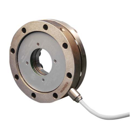
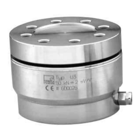
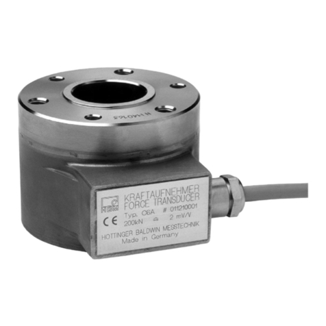
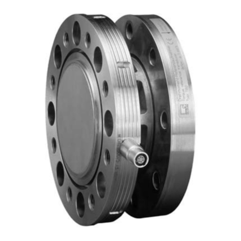
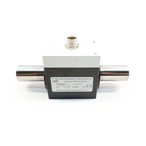
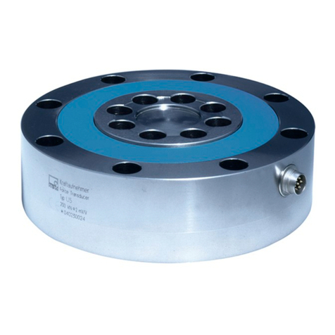
HBM TN User manual

Mounting Instructions | Montageanleitung
English Deutsch
TN

Hottinger Baldwin Messtechnik GmbH
Im Tiefen See 45
D-64293 Darmstadt
Tel. +49 6151 803-0
Fax +49 6151 803-9100
www.hbm.com
Mat.: 7-2001.1639
DVS: A01639_02_X00_00 HBM: public
01.2019
EHottinger Baldwin Messtechnik GmbH.
Subject to modifications.
All product descriptions are for general information only.
They are not to be understood as a guarantee of quality or
durability.
Änderungen vorbehalten.
Alle Angaben beschreiben unsere Produkte in allgemeiner
Form. Sie stellen keine Beschaffenheits- oder Haltbarkeits
garantie dar.

Mounting Instructions | Montageanleitung
English Deutsch
TN

2A01639_02_X00_00 HBM: public TN
English
1 Safety instructions 4........................................
2 Markings used 6............................................
2.1 The markings used in this document 6..........................
2.2 Symbols on the product 7.....................................
3 Scope of supply 7..........................................
4 Application 8...............................................
5 Structure and mode of operation 9...........................
6 Installation 9...............................................
6.1 General notes on mounting 9..................................
6.2 Mbx and Mby bending moment auxiliary bridges 10................
6.3 Mounting position 12..........................................
6.4 Conditions on site 12..........................................
6.5 Adaptations 13...............................................
6.6 Mechanical installation 14......................................
6.6.1 Mounting sequence 15........................................
6.7 Loading capacity 16...........................................
7 Electrical connection 18......................................
7.1 General instructions 19........................................
7.2 Cabling instructions 19........................................
7.3 Recommendations for measuring mode 20.......................

TN A01639_02_X00_00 HBM: public 3
8 Maintenance 21..............................................
9 Options 21..................................................
10 Accessories 21..............................................
11 Specifications 22............................................
12 Dimensions 27..............................................
12.1 Nominal (rated) torque 100 N⋅m ... 5 kN⋅m27.....................
12.2 Nominal (rated) torque 10 N⋅m and 20 kN⋅m28...................

Safety instructions
4A01639_02_X00_00 HBM: public TN
1 Safety instructions
Use in accordance with the regulations
The TN Torque transfer standard may be used for torque measurement and
calibration tasks only. Use for any additional purpose shall be deemed to be
not in accordance with the regulations.
In the interests of safety, the transducer should only be operated as described
in the Mounting Instructions. It is also essential to observe the appropriate legal
and safety regulations for the application concerned during use. The same
applies to the use of accessories.
The transducer is not a safety element within the meaning of its use as
intended. Proper and safe operation of this transducer requires proper trans
portation, correct storage, assembly and mounting and careful operation.
General dangers of failing to follow the safety instructions
The transducer corresponds to the state of the art and is fail‐safe. The
transducer can give rise to remaining dangers if it is inappropriately installed
and operated by untrained personnel.
Everyone involved with the installation, commissioning, maintenance or repair
of the transducer must have read and understood the mounting instructions
and in particular the technical safety instructions.
Remaining dangers
The scope of supply and performance of the transducer covers only a small
area of torque measurement technology. In addition, equipment planners,
installers and operators should plan, implement and respond to the safety
engineering considerations of torque measurement technology in such a way
as to minimize remaining dangers. Prevailing regulations must be complied
with at all times. Reference must be made to remaining dangers connected
with torque measurement technology.

Safety instructions
TN A01639_02_X00_00 HBM: public 5
Conversions and modifications
HBM's express consent is required for modifications affecting the transducers's
design and safety. HBM does not take responsibility for damage resulting from
unauthorized modifications.
Qualified personnel
The transducer may be used by qualified personnel only; the specifications and
the special safety regulations need to be followed in all cases. It is also essen
tial to comply with the appropriate legal and safety regulations for the applica
tion concerned during use. The same applies to the use of accessories.
Qualified personnel means: personnel familiar with the installation, fitting, start-
up and operation of the product, and trained according to their job.
Prevention of accidents
According to prevailing accident prevention regulations, it is essential that after
mounting the transducers the user fits a cover or enclosure as follows:
SThe cover or enclosure must not be able rotate.
SThe cover or enclosure shall protect against crushing or cutting and provide
protection against parts that might come loose.
SThe covers and enclosures shall be installed at a safe distance from moving
parts or shall prevent anyone putting their hand inside.
SThe covers and enclosures shall even be fitted if the moving parts are
installed in areas to which persons do not usually have access.
The above regulations may only be diverged from, if machine parts are already
sufficiently protected owing to the design of the machine or because other pre
cautions have been taken.

Markings used
6A01639_02_X00_00 HBM: public TN
2 Markings used
2.1 The markings used in this document
Important instructions for your safety are specifically identified. It is essential to
follow these instructions in order to prevent accidents and damage to property.
Symbol Significance
CAUTION This marking warns of a potentially dangerous
situation in which failure to comply with safety
requirements can result in slight or moderate physical
injury.
Notice This marking draws your attention to a situation in
which failure to comply with safety requirements can
lead to damage to property.
Important
This marking draws your attention to important
information about the product or about handling the
product.
Tip
This marking indicates application tips or other
information that is useful to you.
Information
This marking draws your attention to information
about the product or about handling the product.
Emphasis
See….
Italics are used to emphasize and highlight text and
references to other chapters and external documents.

Scope of supply
TN A01639_02_X00_00 HBM: public 7
2.2 Symbols on the product
CE mark
The CE mark enables the manufacturer to guarantee that
the product complies with the requirements of the rele
vant EC directives (the declaration of conformity is avail
able at http://www.hbm.com/HBMdoc).
Statutory marking requirements for waste disposal
National and local regulations regarding the protection of
the environment and recycling of raw materials require
old equipment to be separated from regular domestic
waste for disposal.
For more detailed information on disposal, please contact
the local authorities or the dealer from whom you pur
chased the product.
3 Scope of supply
S1x TN Torque transfer standard including bending moment measuring
bridges
S1x Mounting instructions
S3x Connecting cable, 6 m, (with LemoRconnector on transducer side, pig
tails on amplifier side)
S1x DAkkS (national accreditation body for the Federal Republic of
Germany) calibration certificate as per DIN 51309
S1x shipping case with sealing lip

Application
8A01639_02_X00_00 HBM: public TN
4 Application
The TN torque transfer standard is a transducer for measuring static and
dynamic torques in non-rotating operation. The nominal torques are in the
range 100 N⋅m to 20 kN⋅m.
Transfer torque transducers
When used as a transfer torque transducer, the transducer helps to calibrate
reference transducers in test and calibration machines or to compare the refer
ence standards and standard machines of different calibration laboratories.
With transfer transducers, a high degree of reproducibility is important. When
torque is transferred, reproducibility is a measure for the influence of different
observers, test conditions, laboratories, mounting and time situations. So for
transfer, the same conditions have to be created as for calibration in the refer
ence standard.
Reference torque transducers
When used as a reference torque transducer, the TN transducer is mounted in
a calibration machine.
General torque measurements in non-rotating operation
The TN torque transfer standard is a precision transducer designed for use
under laboratory conditions. When used in general industrial applications there
fore, special precautions must be taken to ensure that the requisite ambient
conditions are provided. This includes the temperature and humidity conditions,
the EMC environment and the parasitic loads (bending moments, radial forces
and longitudinal forces). Should the ambient conditions differ, this will affect the
accuracy of the measurement and in serious cases, could interfere with oper
ability.

Structure and mode of operation
TN A01639_02_X00_00 HBM: public 9
5 Structure and mode of operation
The torque transfer standard comprises a measuring body applied with strain
gages (SGs) and cylindrical shaft ends without keys for torque application. The
strain gages are arranged in such a way that an optimum flow of torque
between the shaft end and the strain gage installation point is ensured.
6 Installation
6.1 General notes on mounting
During installation, mechanical components (frame, couplings, shaft‐hub con
nections) affect the deformation behavior of the transfer standard and thus
possibly the measurement characteristic (e.g. zero point, sensitivity, repro
ducibility). The reasons for this could be:
SThe occurrence of additional parasitic loads such as bending moments,
radial and axial forces
SUnsymmetrical torque application to the transducer
We recommend the following countermeasures to minimize these effects:
SAlign the shaft train as accurately as possible.
SUse flexible couplings, e.g. multi-disc couplings.
SApply the torque as evenly as possible to the cylindrical shaft ends through
appropriate clamping elements (clamping hubs). Hydraulically activated
clamping elements have proved effective for the most stringent require
ments.
SEnsure that all shaft train components imposing additional load on the
torque transfer standard have low weight.

Installation
10 A01639_02_X00_00 HBM: public TN
Information
The torque reference transducer is fitted with measuring bridges to measure
the bending moment (one strain gage measuring bridge for each bending
moment in the X and Y direction) as standard. The mounting conditions and
effective bending moments can thus be checked and monitored. The specified
characteristic values are calculated values. Generally, the bending moment
measuring bridges are not calibrated.
6.2 Mbx and Mby bending moment auxiliary bridges
The Mbx and Mby auxiliary bridges are designed to estimate the effective
bending torque load on the torque reference transducer TN in the mounted
state.
Please note that the signal outputs of the Mbx and Mby bending moment
auxiliary bridges do not supply calibrated values. They are predominantly
designed to provide the user with an alignment feature so that the torque
transducer can be installed in the test bench or calibration machine without any
bending moment loads.
For example for the 100 Nm measuring range, with an ideally assumed load
case, a one-sided loading fitting, and free load application in accordance with
the diagram, a force of “0.36” kN is present with an output signal of
UMb=1 mV/V. See table and diagram below.
Measuring
range
Force F during signal out
put
UMbx , UMby ~ 1mV/V
Clear
anceH3
Horizontal
displacement of “P”
kN mm mm
100 Nm 0.36 104 0.32
200 Nm 0.73 104 0.26
500 Nm 1.8 104 0.20
1 kNm 3.49 104 0.18

Installation
TN A01639_02_X00_00 HBM: public 11
Horizontal
displacement of “P”
Clear
anceH3
Force F during signal out
put
UMbx , UMby ~ 1mV/V
Measuring
range
mmmmkN
Measuring
range
2 kNm 5.39 137.5 0.23
5 kNm 9.74 186.5 0.31
10 kNm 13.67 265 0.46
20 kNm 26.68 265 0.38
Measuring side
Torque Bridge
Bending Moment Bridge

Installation
12 A01639_02_X00_00 HBM: public TN
Information
The torque reference transducer is fitted with measuring bridges to measure
the bending moment (one strain gage measuring bridge for each bending
moment in the X and Y direction) as standard. The mounting conditions and
effective bending moments can thus be checked and monitored. Generally, the
bending moment measuring bridges are not calibrated.
6.3 Mounting position
The torque transfer standard can be mounted in any position. With clockwise
torque, there is a positive output signal in conjunction with HBM measuring
amplifiers.
6.4 Conditions on site
The TN torque transfer standard is implemented with IP20 degree of protection
in accordance with EN 60529. Protect the transducer against ordinary dirt,
dust, oil, solvents and moisture.
Tip
When the transducer is used as a transfer standard, the aim is to maintain sta
ble measurement properties (especially sensitivity) over a long period of time.
To achieve this, you must maintain constant ambient conditions (temperature
and humidity) within very tight limits. For this type of use, it is not usually suffi
cient to merely keep to the limits stated for the ambient conditions in the speci
fications.
Calibration laboratories are usually air-conditioned. You should also keep these
ambient conditions as constant as possible during storage and transportation.
For this purpose, we recommend using the supplied HBM shipping case with
sealing lip.

Installation
TN A01639_02_X00_00 HBM: public 13
Fig. 6.1 HBM shipping case with sealing lip
During operation, the prevailing safety regulations for the security of personnel
must be observed.
6.5 Adaptations
Clamping elements are required to mount torque transducers with smooth
cylindrical shaft ends (without keys). When making your selection, please note
the following:
SThe transferable torque of the clamping element must at least match the
nominal torque of the torque transfer standard.
SCorrect function and transferable torque are subject to the clamping ele
ment being designed for the existing fit of the shaft ends.
SFor maximum precision, we recommend hydraulically activated clamping
connections.

Installation
14 A01639_02_X00_00 HBM: public TN
6.6 Mechanical installation
Notice
Handle the transducer carefully. The transducer might suffer permanent dam
age from mechanical shock (dropping), chemical effects (e.g. acids, solvents)
or thermal effects and humidity.
Do not exert great side force putting to put the cable connection under stress!
When mounting the torque transfer standard, make sure that the torque to be
measured will be applied from the measuring side. A sticker is attached to the
housing to identify the measuring side (see Fig. 6.2).
Measuring side
Sticker
Measuring
side
Fig. 6.2 Measuring side identification

Installation
TN A01639_02_X00_00 HBM: public 15
6.6.1 Mounting sequence
Information
When lifting the torque transfer standard, always hold it by the cylindrical shaft
ends, not by the housing. 10 kNVm and 20 kNVm versions are supplied with
transport lugs for lifting.
1 1
2 2
Fig. 6.3 Protective rings (1) and transport lugs (2), viewed from above
SFor nominal torques of 10 kNVm and 20 kNVm only: Remove the protec
tive plastic rings, see Fig. 6.3.
SClean and degrease the shaft ends. Use a piece of cloth or paper soaked in
solvent to do this. When cleaning, make sure that the solvent does not drip
inside the torque transfer standard.
SConnect the cylindrical shaft ends in accordance with the instructions pro
vided by the clamping element manufacturer.
SFor nominal torques of 10 kNVm and 20 kNVm only: Remove the trans
port lugs, see Fig. 6.3.

Installation
16 A01639_02_X00_00 HBM: public TN
6.7 Loading capacity
Torque transfer standards can be used to measure static and dynamic torque.
Please note the following when measuring dynamic torque:
SThe natural frequency f0for the mechanical measuring system depends on
the moments of inertia J1and J2of the connected rotating masses and the
torsional stiffness of the torque transfer standard.
The natural frequency f0for the mechanical measuring system can be deter
mined from the below equation:
f0+1
2p· c
T·ǒ1
J1
)1
J2Ǔ
Ǹf0= Natural frequency in Hz
J1, J2= Mass moment of inertia in kg⋅m2
cT= Torsional stiffness in N⋅m/rad
SThe maximum permissible amplitude of vibration (peak to peak) may be
200 % of the TN's nominal (rated) torque. In all cases the vibration band
width must lie within the loading range defined by -Mnom and +Mnom.
Notice
Even where there is resonance, these mechanical limit values must be fol
lowed. The torsional spring stiffness and the moment of inertia for estimating
the natural frequency can be found in Chap. 11.

Installation
TN A01639_02_X00_00 HBM: public 17
-Mnom 100 %
0
90
70
Nominal (rated) torque Mnom as %
200 % Mnom
amplitude of
vibration
+Mnom 100 %
Fig. 6.4 Permissible dynamic loading

Electrical connection
18 A01639_02_X00_00 HBM: public TN
7 Electrical connection
The torque transfer standard comes supplied with a ready‐made 6‐wire con
nection cable (with LemoRconnector on transducer side, pig tails on amplifier
side). A plug fitting is also possible on request (see chapter 10 “Accessories”,
page 21.).
Measurement signal (+)
Supply voltage (-)
Sensor circuit (-)
Sensor circuit (+)
Supply voltage (+)
Measurement signal (-)
Cable shielding
WH
GY
BK
RD
BU
GN
Sockets Torque/Bending moments
Fig. 7.1 Sockets pin assignment
The connector sockets on the torque transducer TN are labeled accordingly.
bending moment
bending moment
torque
Other manuals for TN
1
Table of contents
Languages:
Other HBM Transducer manuals
Popular Transducer manuals by other brands

Philips
Philips Avalon CTS M2720A quick start guide

Siemens
Siemens SICAM T 7KG966 Product information

Milltronics
Milltronics PL-590 instruction manual

ETH-messtechnik
ETH-messtechnik DRVL Operator's manual

controlair
controlair 595XP Installation, operation and maintenance instructions

DFE
DFE RFA instruction manual

Asco
Asco Power Manager Xp 5200 Series Operator's manual

Trimec
Trimec DUALPULSE 490 instruction manual

MULTISPAN
MULTISPAN CTR-632 manual

turck
turck HART IM33-11-Hi/24VDC Series quick start guide

Airmar
Airmar TRIDUCER B744V Owner's guide & installation instructions

MTS Systems
MTS Systems Temposonics II LDT Installation and instruction manual