HEITECH Recoh-drain User manual

-1-
Installation manual General
Recoh-drain RD1-835CW
We would like to congratulate you on your purchase of the ´Recoh-drain´. The ´Recoh-drain´ is one of most
economically interesting forms of energy saving. The pay-back time is short! Using the ´Recoh-drain´ saves on fossil
fuels. The stocks of fossil fuels are limited and using the ´Recoh-drain´ can help reduce global warming.
1. General
1.1
On average, a shower uses 60 litres of water at a temperature of between 38 and 40 °C. This shower water goes
straight down the drain, wasting a great deal of heat. By running the hot water through the ´Recoh-drain´, this heat
can be transferred to the water on its way to the boiler and the cold water tap of the shower's mixer tap. This heat
transfer takes place during simultaneous flows i.e. while you shower.
Every Recoh-drain has a sticker with technical information and unique number. The sticker must always be legible.
If not legible the guarantee will expire.
Introduction
1.2
The Recoh-drain is placed in a shower drain. The Recoh-drain can excellent be used in apartments, houses with
bathrooms on the ground floor, etc. The height of the heat exchanger is such that it can be placed in almost any
floor. The Recoh-drain comes with matching frame and grate.
When you start showering it takes a little while for the ´Recoh-drain´ to start contributing to the heating of the cold
water. This means the temperature of the shower water will continue to rise for some time. Using a thermostatic
mixer tap is therefore recommendable.
When using the Recoh-drain, the tap limit of the hot water preparer must be taken into account. It is possible the
necessary energy (blending hot water) is lower than the minimal quantity of energy delivered by the hot water
preparer (switch-off point burner).
General
1.3 Description of the heat exchanger
The Recoh-drain consists of several plates over which the waste water flows from the shower. In the plates the
fresh water flows upward. At the bottom of the tank from the heat exchanger, the drain water is being discharged.
Directly below the grate is placed the siphon gutter.
The exceptional thing about the ´Recoh-drain´ is that it has a double barrier between the waste water and the tap
water. The great advantage of a double barrier is that this allows the heat exchanger to be connected directly to
the indoor plumbing. No open connection in the indoor plumbing is therefore required!
1.4 Accessibility
The controllable non-return valve should be visible and accessible. Any possible leaks should be able to be seen.
The heat exchanger is a device and should therefore be accessible. Any possible replacement should be able to
take place without having to take everything apart.
1.5 Connections
The tap water supply pipe should have a controllable non-return valve and a cut-off valve installed in it (these are
already pre-assembled).
The 15mm tubes of the heat exchanger must be connected to the mains water supply pipe by using a fitting that is
demountable. For dimensions and further details please refer to the drawings of the installation instruction.
-2-
1.7
The temperature of the tap water in the heat exchanger sometimes exceeds 25 °C. The temperature should not
exceed that when the ´Recoh-drain´ is not in use (no cold water flowing). The ´Recoh-drain´ may therefore not be
installed next to heat transporting pipes or on warm surfaces such as on floor heating. The cold tap water pipe en
and the ´Recoh-drain´ may therefore not be insulated.
However, the ´Recoh-tray´ contains less than 1 litre of tap water. According to this it may be assumed that no
Legionaire’s Disease will develop.
Safety and Legionaire's Disease
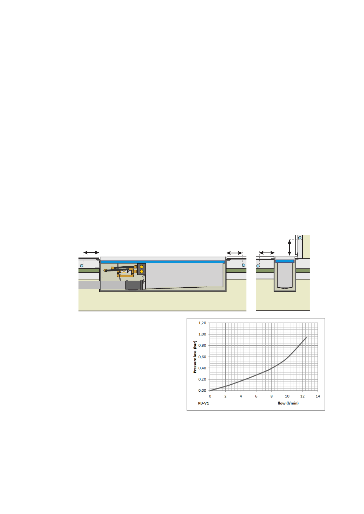
1.8
The figure at right illustrates the pressure loss
of the ´Recoh-drain´, on the tap water side.
At 9,2 l/min the pressure loss is 0,53 bar.
At 12,5 l/min the pressure loss is 0,94 bar.
Loss of pressure
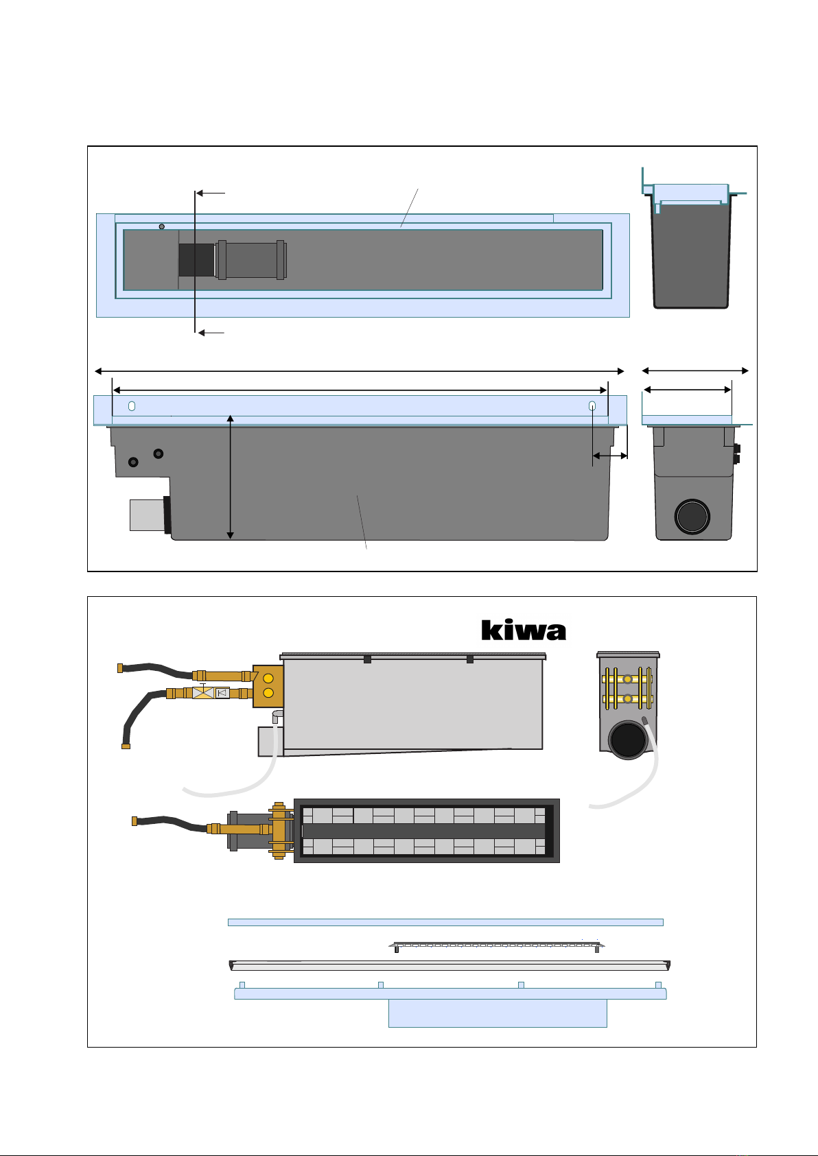
1.6
A
exchanger's tank is made of high-quality plastic. Please refer to the relevant drawing for the dimensions.
Sizes of the gutter frame and grate (between tiles):
Of the wall mounting 123 x 835 mm
Wall mounting 136 (- thickness tiles) x 835 mm
Materials and dimensions
ll the heat exchanger's parts that come into contact with water have been made of copper or brass. The heat
Floor and wall heating:
Assuming a maximum temperature of 50 ° C water in the floor heating system, there must be at least 100 mm
distance to be held to the Recoh-drain system (see drawing).
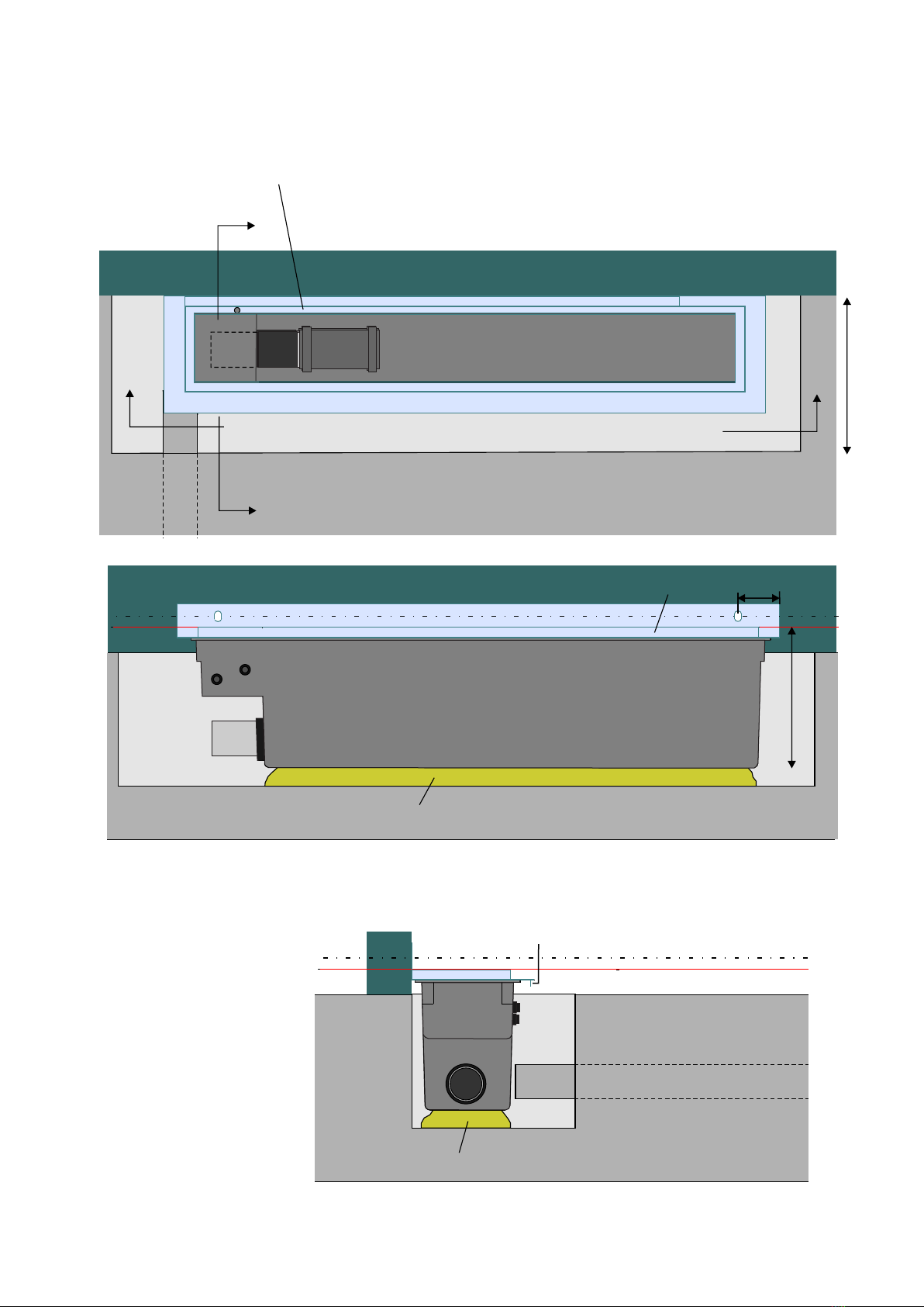
1.9 Design installation
It is necessary to take into account the installation of the Recoh-drain during the design phase of a building.
For the heat exchanger is required a recess in the floor of 1000x230mm and 200/220mm deep (from top screed).
Regarding to this must be taken into account the place in the floor (measurements) and the constructive
consequences of this.
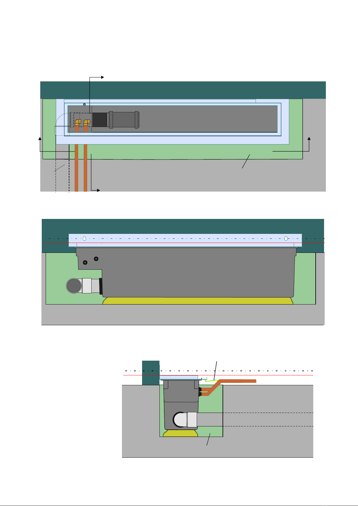
The heat exchanger must also be taken into account in the design of the sewer (gradient). The heat exchanger has a
certain depth that is necessary and on top of this comes the required amount of grade in the sewerage. The
connecting pipe (Ø50mm) until a length of 3.5 meters requires no grade. From 3.5 meters the pipe must be ø75mm
and is a gradient of 5mm/m1 required.
The external diameter of the outlet is 50 mm and can therefore be connected to the standard PP and PVC pipe
dimensions for the sewer. The sewer coming into the recess must be 50 mm.
Deaeration of the Recoh-drain is not necessary, all air will disappear by opening the tap.
100 100
100
100
Topview without heatexchanger
Sideview
Cross section A-A
A
ARVS gutterframe
50 mm discharge
2 Units
Unit 1
-3-
Screed mould template
heat exchanger
Topview
Unit 2
grate
siphon gutter
hair stopper
rubber seal
2. Overview of components of the Recoh-drain
835
895
136
168
200
50
Sideview
-4-
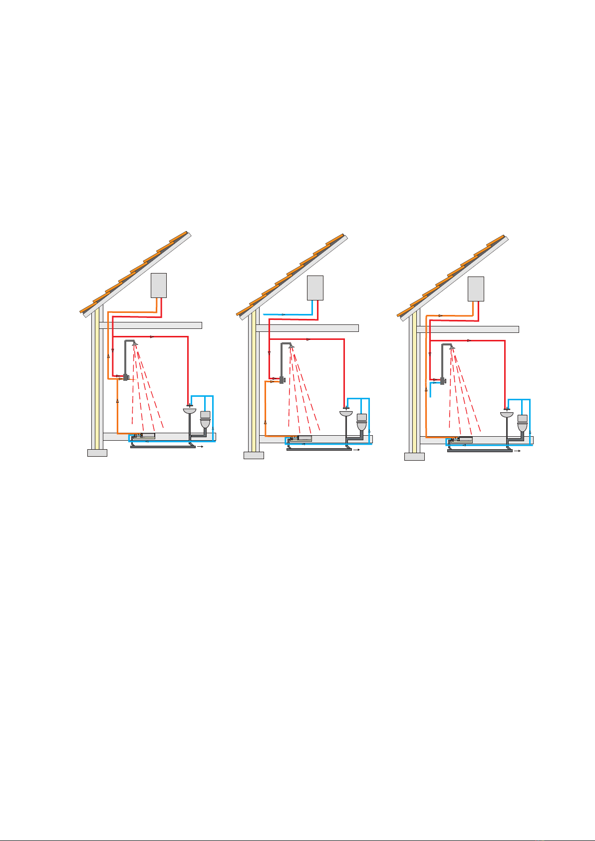
3.1 Systemen A, B and C
The inlet side of the ´Recoh-drain´ can be connected to the tap water system in the house. The outlet side can be
created in several ways, namely:
A. Combined connection of the heat exchanger to the cold water connection of the shower's mixer tap and
the water heater.
B. Connection solely from the heat exchanger to the tap water connection on the shower's mixer tap.
C. Separate connection of the cold water connection to the water heater.
The largest saving is achieved by using System A
3 Installation.
System B
boiler
Discharge
tap water
supply
mixer
tap
Recoh-drain
preheated
tap water
boiler
Discharge
tap water
supply
mixer
tap
System A
Recoh-drain
preheated
tap water
System C
boiler
Discharge
tap water
supply
mixer
tap
Recoh-drain
preheated
tap water
Should you have any comments or additions to this manual, please do inform us (info@hei-tech.nl).
Edition : 04-2014
In construction phase: don’t flush cement, glue, etc. through the Recoh-drain.
Maintenance and cleaning according to the userguide.
It is not recommended to flush shaving gel and toothpaste since they are very sticky and could adhere to the plates
of the heatexchanger.
4. Maintenance and cleaning
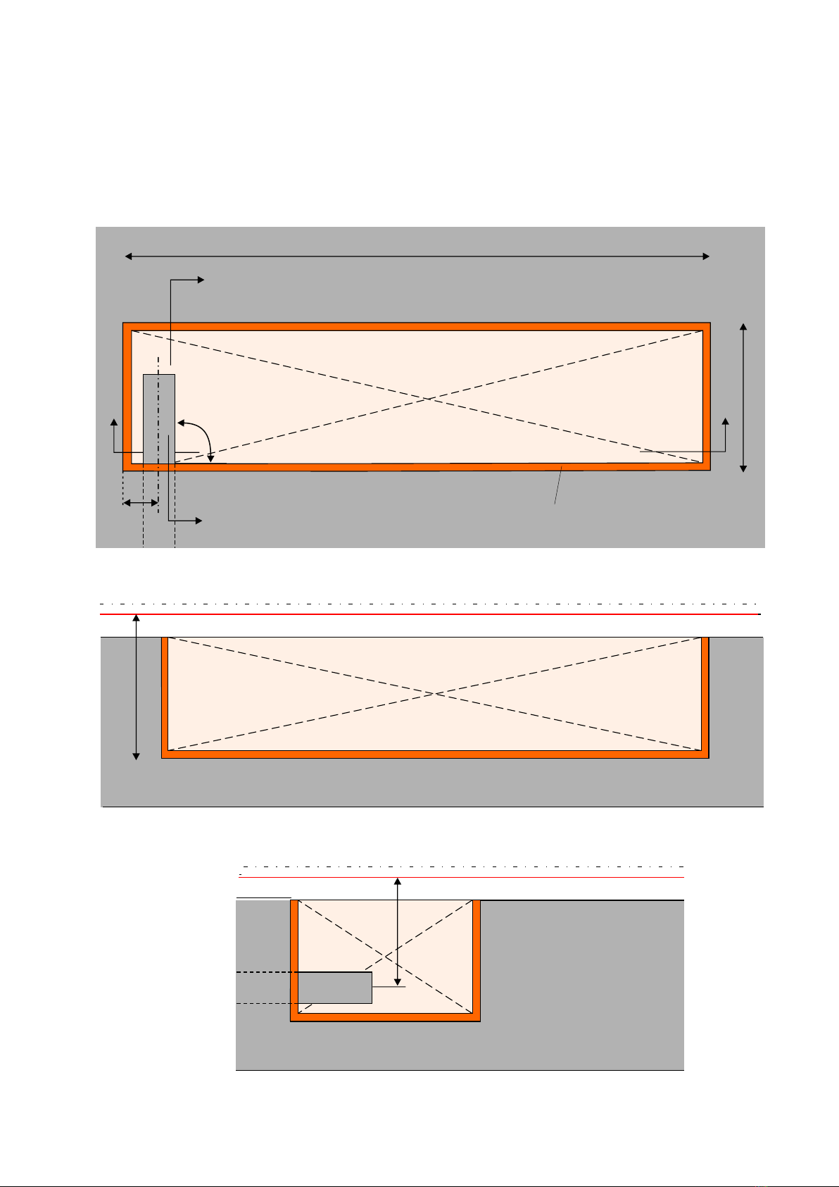
220
162
1000
200
A
B
B
A
mould
discharge
50mm
60
90o
-5-
5 Installing unit 1.
5.1 Gap in concrete floor
level tiled floor
level tiled floor at Recoh-drain
Cross section A-A
level tiled floor at Recoh-drain
level tiled floor
Cross section B-B
200
B
B
A
quick set mortar K70
place on right position
level tiled floor
level tiled floor
at Recoh-drain
200
quick set mortar K70
level horizontal
-6-
earth connection
A
5.2 Mounting unit 1
Cross section A-A
level tiled floor
at Recoh-drain
level tiled floor
Cross section B-B
Attention: Unit 1 must be leveled horizontal.
50
A
B
B
A
screed
water connection
discharge
-7-
level tiled floor
level tiled floor
at Recoh-drain
level tiled floor
level tiled floor
at Recoh-drain
screed
earth connection
5.3 Connect discharge and waterconnections
Cross section A-A
Cross section B-B
level tiled floor
wet room
membrane
Kit all-around.
-8-
a wet room membrane.
After applying the tiles,
kit the gutter frame
all-around.
Before kit:
Primer frame en edges of tiles
to achieve a good connection.
(or 2 component kit).
We recommend to apply
level tiled floor
Gradient
Cross section A-A
Cross section B-B
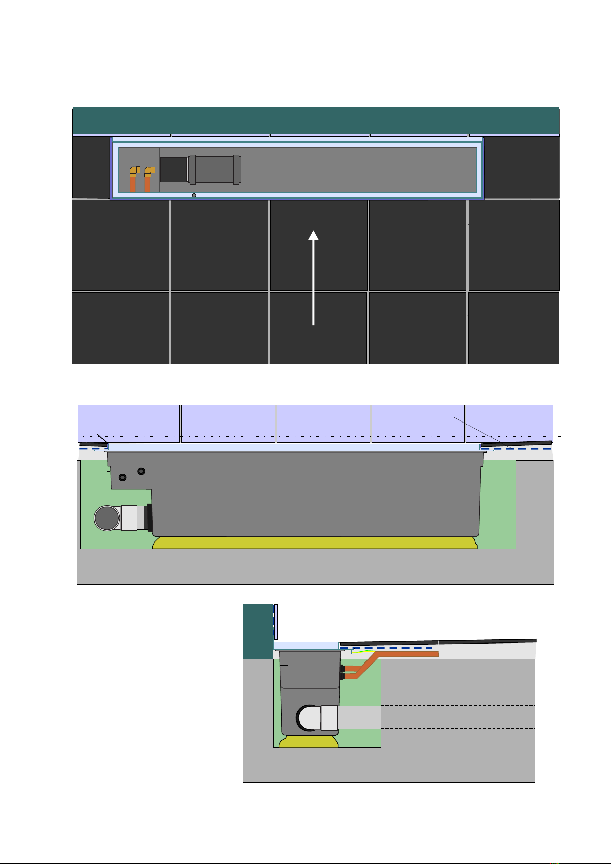
5.4 Screed with tiles
connect leakage tube
-9-
connect sliding sleeve
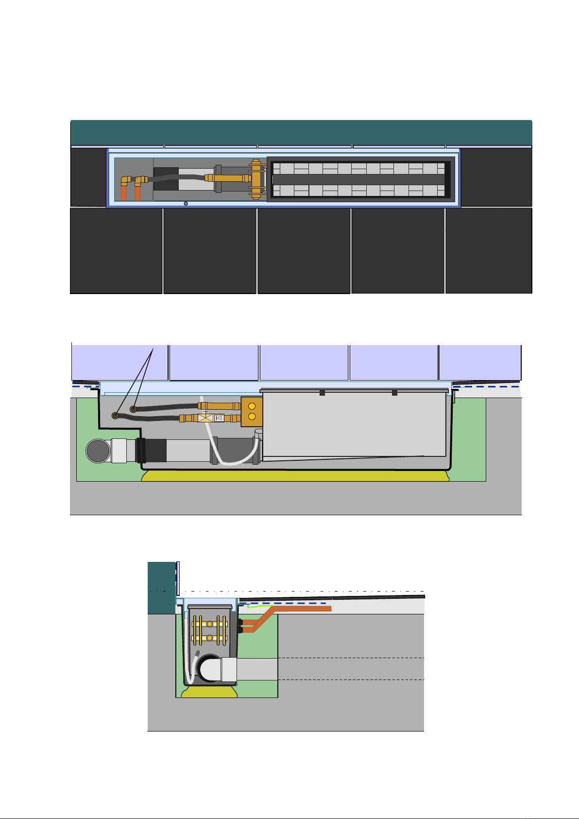
6.1 Place Recoh-drain heatexchanger
6 Installing unit 2.
Cross section A-A
Cross section B-B
Connect the clips at the
sides behind the gutter
frame.
locking / clips
-10-
flexible tube 1/2"
female
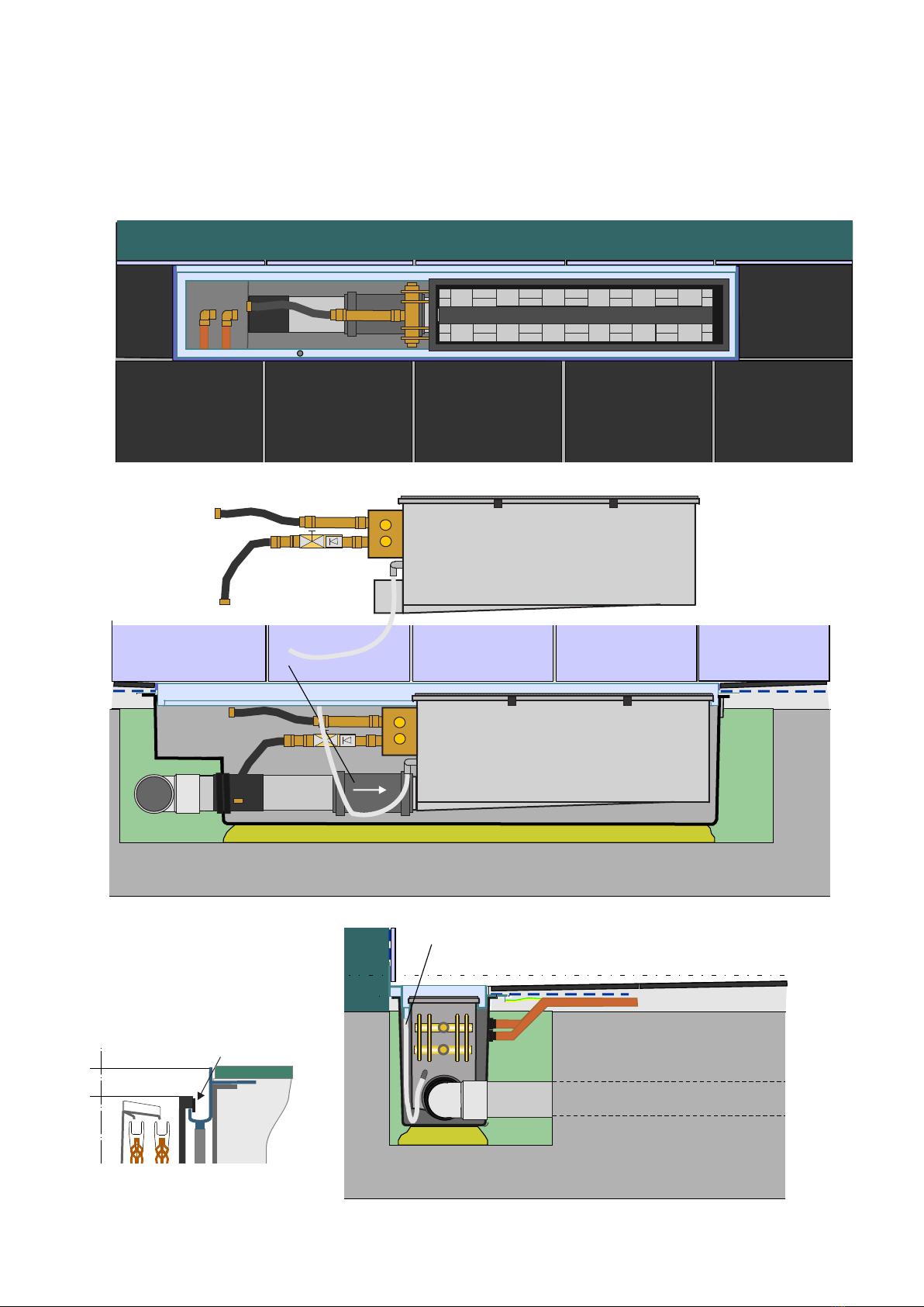
6.2 Conect fresh water connections
Cross section A-A
Cross section B-B
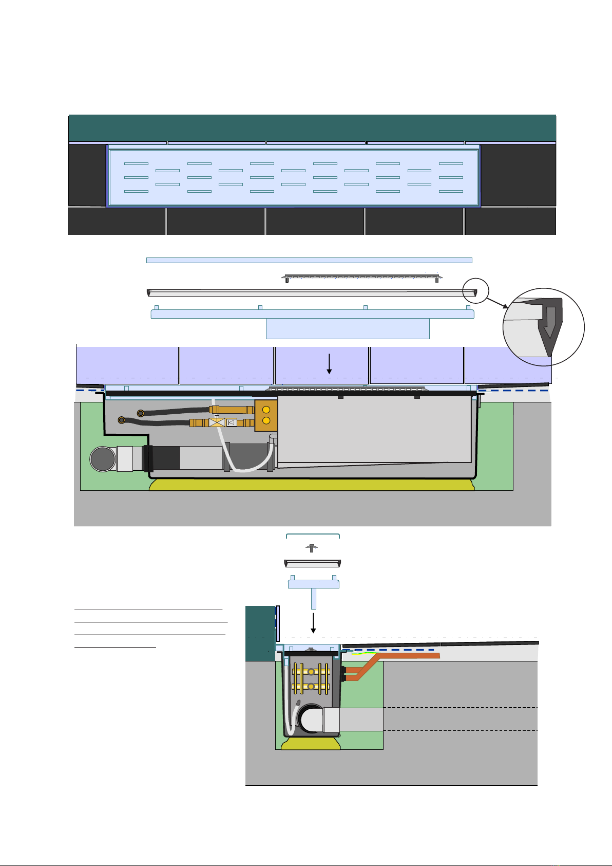
grate
siphon gutter
hair stopper
rubber seal
-11-
6.2 Place siphongutter, rubber seal, hairstopper and grate
Make sure the point of
the rubber seal is
pointed downwards.
Cross section A-A
Cross section B-B
Rubber seal
Press firmly from the center to the
sides.
Note: Don’t push the rubber seal to
deep, upper side equal to top siphon
gutter. Prevent closing the discharge
in the gutter frame.
Order of placing:
1. siphon gutter
2. rubber seal
3. hairstopper
4. grate
First place siphongutter
than rubber seal.
This manual suits for next models
1
Table of contents


