Heitronics KT15 II User manual

INFRARED RADIATION
THERMOMETER
KT15 II
Operating Instructions
95582944
41/09/18e (valid from Serial Number 10301)
All rights reserved! The reproduction, transmission or use
of this document or its contents is not permitted without
express written authority. Offenders will be liable for
damages. All rights, including rights created by patent
grant or registration of a utility model or design, are
reserved. Heitronics GmbH reserves the right to make
modifications and improvements in their design without
prior notice.
(c) HEITRONICS Infrarot Messtechnik GmbH
HEITRONICS
Infrarot Messtechnik GmbH
Kreuzberger Ring 40
D-65205 Wiesbaden
Tel.: +49 (0)611 97393-0
Fax: +49 (0)611 97393-26
Internet: www.HEITRONICS.com

SAFETY INSTRUCTIONS
Please read carefully the instructions given in TECHNICAL SPECIFICATIONS, especially
the connection and operating instructions as well as the connection instructions and con-
figurations dealt with in SYSTEM START-UP.
ATTENTION
In case of wrong connection,
the device might be destroyed.
The Infrared Radiation Thermometer is an optical measuring instrument. Dirty lenses will
lead to measuring errors. Please pay attention to the instruction given in MAINTENANCE
AND CALIBRATION.
HEITRONICS production meets the latest technical development thereby applying sophis-
ticated components. Nevertheless, functional errors may occur in exceptional cases. The
failure of an instrument may cause a measuring value being issued which seems to be
correct, but is wrong. Please pay attention to the instructions given in MAINTENANCE
AND CALIBRATION.
Only when using a female connector with cable or a dummy plug attached to the plug of
the device - in addition to the equipment sealing - the specified system of protection can
be achieved.
Operation with Laser: Devices completely mounted and equipped with integrated
laser meet the safety requirements of Laser class 2.
Before handling the lens in any way, the voltage supply is to be switched off or the
connecting plug is to be pulled out to ensure that the laser will not switch on automatically.
ATTENTION
The Laser must not be switched on, if the lens
of the Infrared Radiation Thermometer is removed.
The integrated laser can only operate up to the upper limit of the ambient temperature
of the Infrared Radiation Thermometer (60 °C).
ATTENTION
The Laser will be switched off
at an ambient temperature ≥60 °C
to defend it from destruction.
95582944 SAFETY INSTRUCTIONS KT 15 II
03/03/14eHEITRONICS Infrarot Messtechnik GmbH

Erklärung über die Konformität
DECLARATION OF CONFORMITY
Diese Erklärung gilt für folgende Erzeugnisse:
This declaration is valid for the following products:
Geräteart: Infrarot Strahlungspyrometer
Type of instrument: Infrared Radiation Pyrometer
Typenbezeichnung: KT15 II Serie
Designation of model: KT15 II Series
Diese Erklärung wird abgegeben durch
This declaration is issued by
HEITRONICS Infrarot Messtechnik GmbH
Kreuzberger Ring 40
65205 Wiesbaden, Germany
Hiermit wird bestätigt, dass die Produkte gemäß den Richtlinien des Rates
zur Angleichung der Rechtsvorschriften der Mitgliedsstaaten über die
elektromagnetische Verträglichkeit (89/336/EWG) mit den unten genannten
Normen übereinstimmen:
In accordance with the EU-Directive of Electro-magnetic-compatibility (89/336/EWG)
the manufacturer declare, that the device described above is conform to the
essential requirements of the EU-Directives:
EN 55011 Class B
EN 61326
Wiesbaden, 15. Juli 2003
Wiesbaden, July 15, 2003

PREFACE
The remarkable features of the HEITRONICS devices are a
design suitable for specific application as well as an uncom-
plicated operation. Nevertheless, it is recommended to read
the entire instruction manual before putting the instruments
into operation.
Please observe the safety instructions as well as the particu-
larly emphasized annotations when reading the pertinent in-
struction to the operation.
The operating instructions are primarily directed to the user.
They contain the information and instructions necessary to
successfully use the instruments including all options.
If you still have any questions after having read this instruc-
tion manual, please contact us. Our staff will be at your dis-
posal.
RoHS-CONFORMITY
This product is in conformity with Directive 2011/65/EU of the
European Parliament and of the Council of 8 June 2011 on
the restriction of the use of certain hazardous substances in
electrical and electronic equipment.
LASER-CONFORMITY
The built-in laser complies with:
ISO IEC EN 60825-1
FDA ANSI 21 CFR 1040//Laser Notice No. 50
EU Radiation Safety Optic EU directive 2006/25/EC//
OStrV 2010-07//TROS
The FDA Accession No. is: 1820088-000
95582944 PREFACE KT15 II
03/03/18e HEITRONICS Infrarot Messtechnik GmbH

CONTENTS
SAFETY INSTRUCTIONS
DECLARATION OF CONFORMITY
PREFACE
RoHS-CONFORMITY
LASER-CONFORMITY
CONTENTS......................................................................................................0-1
DATA SHEET...................................................................................................1-1
GENERAL ........................................................................................................2-1
Measuring temperatures using Infrared Radiation Thermometers..............2-1
Infrared Radiation Thermometers for GENERAL APPLICATION .......................2-2
Infrared Radiation Thermometers for measuring METALS............................2-3
Infrared Radiation Thermometers for measuring PLASTICS..........................2-3
Infrared Radiation Thermometers for measuring GLASS..............................2-4
Infrared Radiation Thermometers for measuring GASES .............................2-4
TECHNICAL SPECIFICATIONS ......................................................................3-1
Basics.........................................................................................................3-1
Technical Information 'Protective Cooling Jacket'.......................................3-3
Assignment for 12-pin connector for RS232-Interface ................................3-4
Assignment for 12-pin connector for RS485-Interface ................................3-6
Assignment for 7-pin connector ..................................................................3-7
Legend table "Temperature resolution".......................................................3-8
Temperature resolution
KT15.01 II / KT15.02 II..............................................................................3-8
KT15.21 II...................................................................................................3-9
KT15.23 II / KT15.24 II............................................................................3-10
KT15.25 II.................................................................................................3-11
KT15.41 II / KT15.42 II............................................................................3-12
KT15.43 II.................................................................................................3-13
KT15.45 II.................................................................................................3-14
KT15.62 II.................................................................................................3-15
KT15.63 II.................................................................................................3-16
KT15.69 II.................................................................................................3-17
KT15.81 II / KT15.82 II............................................................................3-18
KT15.83 II / KT15.85 II............................................................................3-19
START-UP........................................................................................................4-1
Mounting.....................................................................................................4-1
Fig. Mounting KT15 II Protective Cooling Jacket ........................................4-1
Electrical Connection..................................................................................4-2
Operation without serial interface................................................................4-2
Operation with serial interface.....................................................................4-2
Optical Adjustment......................................................................................4-3
Aiming via focus laser.................................................................................4-3
Aiming via pilot laser...................................................................................4-3
Aiming via Laserpointer LP15.....................................................................4-3
Installation Protective Cooling Jacket WK15...............................................4-4
0-1
95582944 CONTENTS KT15 II
18/03/18e HEITRONICS Infrarot Messtechnik GmbH

OPERATION AND APPLICATION...................................................................5-1
Application................................................................................................5-1
Check routines.....................................................................................5-1
Continuous measurement of ambient temperature..............................5-2
Use of digital input ...............................................................................5-3
Use of digital outputs...........................................................................5-4
Monitoring the device function during operation...................................5-4
Use of maximum and minimum value memories .................................5-5
Operation via keyboard............................................................................5-8
Operation of the Menu.........................................................................5-8
Main Menu...........................................................................................5-9
Submenu: Temp / Info / Emi ............................................................5-10
Submenu: Tamb...............................................................................5-11
Submenu: Resp / Memo...................................................................5-12
Submenu: HiAI / LoAI .......................................................................5-13
Submenu: Laser / Unit......................................................................5-14
Submenu: Aout.................................................................................5-15
Submenu: Uart..................................................................................5-16
Submenu: Cal...................................................................................5-17
Submenu: Conf.................................................................................5-18
Submenu: Test .................................................................................5-19
Communication via interface.................................................................5-20
Preparing the device for operation with interface RS232C................5-20
Using the interface ...........................................................................5-20
Control of communication .................................................................5-20
Data transfer from KT15 II for evaluation purposes...........................5-21
Commands .......................................................................................5-21
Delimiter............................................................................................5-21
Input buffer........................................................................................5-21
Description of commands.........................................separate instructions
MAINTENANCE AND CALIBRATION .............................................................6-1
General information ....................................................................................6-1
Cleaning the lens........................................................................................6-1
Checking the display accuracy....................................................................6-1
FIGURES AND TABLES..................................................................................8-1
Spectral emissivity of various materials ......................................................8-2
Total emissivity of some materials at 20 °C ................................................8-2
Emissivity of foils ........................................................................................8-3
Spectral emissivity of Infrared Radiation Thermometers and
transmission curves of various synthetic materials .....................................8-4
Spectral emissivity ε, transmissivity τ and
reflectivity ρ of glass ...................................................................................8-5
Housing dimensions KT15II........................................................................8-6
Field of view................................................................................................8-8
Transmission curves (illustrated in a diagram)..........................................8-9ff
WARRANTY CONDITIONS
SERVICE ADDRESSES
0-2
95582944 CONTENTS KT15 II
17/01/15e HEITRONICS Infrarot Messtechnik GmbH

1 DATA SHEET
Type ..........................................................................................................
Serial No.
.......................................................
Spectral response
.......................................................
Temperature range
...............................................
Calibration factor
........................................................
Lens................................................
Spacer............................................
Detector..........................................
Digital Interface...............................
Options
....................................................................................................................................
....................................................................................................................................
Accessories
....................................................................................................................................
....................................................................................................................................
Code ...........................................................................................................................
Further data.................................................................................................................
....................................................................................................................................
Hereby it is confirmed that the Infrared Radiation Thermometer specified above
conforms to the data indicated in the specifications.
Tester: Wiesbaden,
1-1
95582944 DATA SHEET KT15 II
03/01/15e HEITRONICS Infrarot Messtechnik GmbH

2 GENERAL
2.1 Measuring temperatures using Infrared Radiation Thermometers
Above a temperature of absolute zero, which is approx. - 273 °C or 0 K, all bodies
emit electromagnetic radiation, the wavelength and density of which depend on the
temperature. Up to a temperature of approx. 600 °C, the wavelength of the radiation
can be found exclusively within the infrared range (thermal radiation). It is only at
higher temperatures where part of this radiation is emitted in the form of visible light.
The radiation emitted by the body (radiation density) also depends on the surface of
the individual body. At a fixed temperature, the maximum radiation density is emitted
by a "blackbody" source of radiation. All real bodies only emit a fraction of this radia-
tion density at the same temperature. The ratio of this fractional part to the maximum
radiation density is called the emissivity ε. Naturally, the emissivity is always < 1. It
depends on the nature of the surface of the material, on the material itself and on the
wavelength. If the emissivity is known, the temperature of the object can be deter-
mined by measuring the infrared radiation emitted by the very object.
Devices used to measure this kind of radiation are called Infrared Radiation Ther-
mometers.
As the measurement is effected without the Infrared Radiation Thermometer being in
contact with the object, no distortion of the temperature field due to heat dissipation
need to be feared, as is the case, e.g., with probe-type thermometers.
The Infrared Radiation Thermometer is a measuring transducer, which receives the
infrared radiation emitted by the measuring object itself and transforms it into a
standardized output signal.
All optic and electronic components are located in a small housing of a solid con-
struction, which is made from die-cast metal so that the installation of a Infrared Ra-
diation Thermometer is possible even in narrow spaces.
By selecting a number of various lenses and detectors, it is possible to generously
modify the measuring field, if the measuring distance is given.
For the application of the Infrared Radiation Thermometer under high ambient tem-
perature, water-cooling, air purge fittings and vacuum tight lenses can be delivered
as accessories.
2-1
95582944 GENERAL KT15 II
02/03/14e HEITRONICS Infrarot Messtechnik GmbH

2.2 Infrared Radiation Thermometers for GENERAL APPLICATION
The Infrared Radiation Thermometers series KT15.81 II / KT15.82 II /KT15.83 II are
used to measure surface temperatures within a temperature range of - 50 °C to
1000 °C. The spectral sensitivity can be found within the range of the atmospheric
window, which is between 8 and 14 µm. As the atmospheric transmissivity is very
high in this spectral range, no weakening of the infrared radiation due to CO2or to
water vapor contained in the air is to be expected.
To meet especially high requirements as to the transmission of the atmosphere as it
is a case e.g. when carrying out meteorological measurements Infrared Radiation
Thermometer KT15.85 II is suitable.
The KT15.81 II / KT15.82 II / KT15.83 II can be employed in the measuring of tem-
peratures during the production and processing of plastics, rubber, paper, textiles,
paint, ceramics etc. The emissivity of various metals is shown in figure 10 (chapter 8:
Illustrations).
The devices can also be used to measure the temperature of objects exposed to in-
frared radiation, since the radiation maximum of infrared radiators is within the range
of shorter wavelengths, which do not cause the Infrared Radiation Thermometers
KT15.81 II / KT15.82 II / KT15.83 II to react.
The Infrared Radiation Thermometer KT15.81 II is used in the spectral range of 8 to
10 μm. Besides being used for large-surface measurement, this Infrared Radiation
Thermometer type is also suitable for measuring thick foils.
The Infrared Radiation Thermometer KT15.82 II is applied for the standard measur-
ing range of 8 to 14 µm thereby guaranteeing a good signal resolution.
The Infrared Radiation Thermometer KT15.83 II provides a particularly high signal
resolution owing to its large spectral range. Therefore, it is very well suited for meas-
uring low temperatures.
For high requirements on the transmission of the atmosphere, such as found in me-
teorological measurements, the KT15.85 II type is available. This device type oper-
ates within the spectral ranges of 9.6 to 11.5 µm, where the transmission of the at-
mosphere is extremely high.
2-2
95582944 GENERAL KT15 II
02/03/14e HEITRONICS Infrarot Messtechnik GmbH

2.3. Infrared Radiation Thermometersfor measuring METALS
The spectral emissivity of the Infrared Radiation Thermometers KT15.01 II / KT15.02
II is 2 to 2.7 µm and 2 to 4.5 µm. Within this spectral range, metals and metal-oxides
show a relatively high spectral emissivity. This is why the device is particularly well
suited to measure the temperatures of these materials. Since the atmospheric trans-
missivity is high within the spectral range of 2 to 2.7 µm, distortions of the measured
value owing to absorption of water vapor and CO2in the air can be ignored
(Fig. 11, ILLUSTRATIONS).
The Infrared Radiation Thermometer type KT15.01 II is used for measuring tempera-
tures from 300 °C onwards; the Infrared Radiation Thermometer type KT15.02 II is
suitable for measuring temperatures from 200 °C onwards. Temperatures from 500
°C respectively 700 °C onwards are preferably measured by means of the spectral
pyrometers of the series KT18S or the quotient pyrometers of the series KT18R.
2.4 Infrared Radiation Thermometers for measuring PLASTICS
These types of Infrared Radiation Thermometers are employed for the measuring of
surface temperatures of plastics within a temperature range of 0 to 600 °C.
These Infrared Radiation Thermometers are equipped with narrow-band infrared fil-
ters.
KT15.21 II measures radiation at 3.43 µm,
KT15.23 II measures radiation at 6.8 µm,
KT15.24 II measures radiation at 7.93 µm,
KT15.25 II measures radiation at 8.05 µm.
Within these spectral ranges, virtually all synthetic materials have strong absorption
bands so that even thin foils show high emissivity.
The Infrared Radiation Thermometer KT15.21 II is suitable for most foils from 100 °C
onwards.
The Infrared Radiation Thermometer KT15.23 II measures thin foils made from poly-
ethylene, polypropylene, polyisobutane, polynitrile, polystyrene and similar materials
from 0 °C onwards.
The Infrared Radiation Thermometer KT15.24 II and KT 19.25 II measure thin foils
polyester as well as foils made from
- acrylic,
- cellulose,
- fluorine compounds,
- polycarbonate,
- polyamide,
- polyurethane,
- polyvinylchloride
and similar materials after analysis from 0 °C onwards.
2-3
95582944 GENERAL KT15 II
02/03/14e HEITRONICS Infrarot Messtechnik GmbH

2.5 Infrared Radiation Thermometersfor measuring GLASS
KT15.42 II is suitable for measuring glass and quartz. The spectral sensitivity is 4.9
to 5.5 µm. The emissivity of glass is very similar to the emissivity of a blackbody radi-
ator within this spectral range. Furthermore, this spectral range eliminates any dis-
turbing influences resulting from the strong absorption bands of water vapor at 6.2
µm.
The Infrared Radiation Thermometers KT15.01 II and KT15.41 II are not measuring
the surface but the average value of temperatures up to a certain penetration depth
(glass volume). The lower limits are 300 °C for KT15.01 II and 400 °C for KT15.41 II.
The types KT15.42 II and KT15.43 II measure the surface temperature from 100 °C
respectively from 0 °C onwards.
2.6 Infrared Radiation Thermometers for measuring GASES
By means of narrow-band filters, the selective measurement of temperature of cer-
tain gases is possible. A rather long response time is to be chosen since the radiation
energy is very low.
KT15.21 II measures hydrocarbon from 100 °C onwards.
KT15.62 II measures materials within the absorption range of carbon dioxide and
carbon monoxide,
KT15.63 II measures carbon monoxide selectively,
KT15.64 II is provided for nitrogen oxide and
KT15.69 II has been especially developed for determination of combustion tempera-
tures.
Using KT15.41 II, objects can be measured through gases and flames from 400 °C
onwards.
2-4
95582944 GENERAL KT15 II
02/03/14e HEITRONICS Infrarot Messtechnik GmbH

3-1
95582944 TECHNICAL SPECIFICATIONS KT15 II
21/03/12e HEITRONICS Infrarot Messtechnik GmbH
3 TECHNICAL SPECIFICATIONS
Spectral sensitivity: DATA SHEET
Temperature measuring range: DATA SHEET
Temperature resolution: Tables (Page 3-7ff)
Accuracy (provided that the emissivity has been correctly set, after a warm-up period of 15 min.):
± 0.5 °C plus 0.7 % of the temperature difference
between the housing containing the measuring in-
struments and the object to be measured
or: value of temperature resolution.
The higher value shall prevail.
Long-time stability: better than 0.1 ‰ of the absolute measuring tem-
perature in Kelvin/month
Lens used: DATA SHEET
Possible lenses: OPTIONS AND ACCESSORIES
Target diameter (95 %): The target diameter depends on the lens and the
detector used in each individual case.
When short-focus lenses are used, the distance
within which the minimum measuring field can be
found varies by ± 4%.
Field of view: Marking the field of view is carried out by means of
different accessories.
OPTICAL ADJUSTMENT (chapter 4.5)
Radiation detector: HEITRONICS pyroelectric detector
Permissible ambient temperature: - 20 ... + 60 °C
For higher ambient temperatures, cooling and pro-
tecting jackets are available.
OPTIONS AND ACCESSORIES and
TECHNICAL INFORMATION (page 3-3)
Storage temperature: - 20 … + 70 °C
Weight: approx. 0.55 kg
Dimensions: FIGURES: Fig. 15
Operating voltages: AC: 12 (-10 %) ... 24 V (+ 10 %)
48 ... 400 Hz
DC: 10.5 ... 30 V
power consumption: ≤3.5 W
Type of protection: IP65

Analog output: possible signal outputs (variable by programming)
0 ... 20 mA, 4 ... 20 mA
0 ... 1 V, 0 ... 10 V
Lower temperature value (T.low): minimum temp. value for analog signal
Upper temperature value (T.end): maximum temp. value for analog output
Minimum temperature difference: depends on final temperature (T.end)
The following values will result:
Final temperature
Minimum temperature
difference
≤ 150 °C
50 °C
≤ 200 °C
100 °C
≤1000 °C
200 °C
> 1000 °C
400 °C
Load of analog output: current output: load ≤550 Ohm
voltage output: load ≥10 kOhm
Resolution of analog output: 16 bit
Digital interface V24 (RS232C): 9.6 ... 115.2 kBaud
Response time (90 %): variable by programming
KT15 IIP: 0,005; 0,01; 0,03; 0,1; 0,3; 1; 3; 10; 30;
60; 120; 240; 360, 480 und 600 s
KT15 IID: 0,03; 0,1; 0,3; 1; 3; 10 s
Protection against oscillation: DIN 40046 Bl. 8; test: Fc
vibration strength: A B1 E
frequency range: 10 to 55 Hz
amplitude: +/- 0.2 mm
duration of test/position: 30 min
Connector type: miniature circular connector, Franz Binder GmbH,
type 99-5630-15-12, series 423, 12-pin and
type 99-5626-15-07, series 423, 7-pin
Options:
Thermal switch: switching temperature: > 70 °C
load: voltage: ≤ 48 V, current: ≤ 0.5 A
alternative:
Analog input: 0 … 10 V
alternative:
Digital input:floating contact or 0 … 30 V (low 1 V, high 4 V)
Laser: SAFETY INSTRUCTIONS
LASER-CONFORMITY
Laser
type Protection
class Output Wave-
length Form Diameter
Max.
ambient
temperature
Pilot
laser
2 < 1 mW 650 nm round beam Ø 3 mm @ 1 m distance 60.0 °C
Focus
laser
2 < 1 mW 650 nm
cross lines
with centering circle
adapted to field of view
in the focus distance
60.0 °C
3-2
95582944 TECHNICAL SPECIFICATIONS KT15 II
27/03/18e HEITRONICS Infrarot Messtechnik GmbH

Technical Information
Cooling Jacket WK15
The HEITRONICS Infrared Radiation Thermometers can be operated at an environmental
temperature of up to 60°C without any additional coolants. If the environmental tempera-
tures are higher than that mentioned above, cooling fittings can be used.
Basically, the cooling jacket WK15 can be cooled with air or water. The possible maximum
environmental temperatures are higher for water cooling than for air cooling (individual
Data Sheet).
If the cooling process is too strong, i.e. if the cooling air / cooling water is too cold, this
may result in condensate as soon as cooling medium falls below the dew point. To pre-
vent this from occurring, the cooling air / cooling water must have a minimum temperature
as a function of the relative humidity.
The following table specifies the minimum temperature of the cooling air / cooling water as
a function of the environmental temperature and the relative humidity of the environmental
air.
Minimum temperature of the cooling air / cooling water
Relative air humidity (of the environmental air)
Environmental
air temperature
/°C 2% 4% 10% 20% 30% 50% 70%
30.0 5.0 5.05.06.011.019.025.0°C
40.0
5.0
5.0
5.0
13.0
20.0
28.0
34.0
°C
50.05.05.010.021.028.038.045.0°C
60.0
5.0
5.0
18.0
28.0
38.0
47.0
54.0
°C
70.05.09.024.038.045.057.0nm °C
80.05.015.032.045.055.0nm nm °C
90.0
10.0
21.0
38.0
52.0
nm
nm
nm
°C
>100.015.027.045.060.0nm nm nm °C
Legend: nm * Operation not possible since the minimum temperature is above 60 °C
Table: Minimum temperature of the coolant
3-3
95582944 TECHNICAL SPECIFICATIONS KT15 II
28/06/18e HEITRONICS Infrarot Messtechnik GmbH
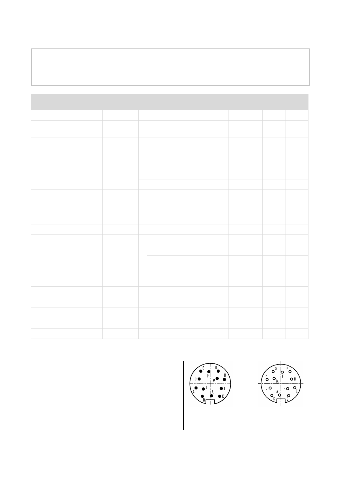
Assignment for 12-pin connector – for RS232-Interface
ATTENTION
In case of wrong connection, the device might be destroyed.
Cores
color
Code
DIN IEC 757
Plug-in
contacts
Function
RS232
9-pin
RS232
25-pin
red
RD
A
CTS
7
4
white WH B
-
supply voltage
(AC or DC)
green/white
alternative:
grey/pink
or
colorless
GNWH
GYPK
colorless
C
+
+
thermal switch
analog input
digital input
note 1
isolated digital input (DI)
5V- or 24V-logic
note 1,2
Open-collector output 2 (DO2)
note 1,4
grey GY D
-
-
thermal switch
analog input
digital input
note 1
DI/DO1/DO2 (Gnd)
note 1,2,3,4
yellow
YE
E
+
analog output
brown/white
alternative:
red/blue
or
orange
BNWH
RDBU
OR
F
DTR
6
6
open-collector output (DO1)
note 1,3,4
pink
PK
G
TXD
2
3
violet
VT
H
RTS
8
5
blue
BU
J
RXD
3
2
black
BK
K
-
datacom (data ground)
5
7
brown
BN
L
+
supply voltage (AC or DC)
green
GN
M
-
analog output
Notes:
1: Hardware-Option, see Data Sheet (1-1)
2: Valid for Interface map with isolated digital input.
3: Valid for Interface map with open-collector output.
4: Valid for Interface map with 2 open-collector output.
Further information
next page
12-pin plug connector 12-pin socket-outlet
3-4
95582944 TECHNICAL SPECIFICATIONS KT15 II
28/06/18e HEITRONICS Infrarot Messtechnik GmbH

Assignment valid for RS232-Interface
Only 1 variant possible (Version Data Sheet page 1-1)
3-5
95582944 TECHNICAL SPECIFICATIONS KT15 II
25/01/15e HEITRONICS Infrarot Messtechnik GmbH

Assignment for 12-pin connector – for RS485-Interface
ATTENTION
In case of wrong connection, the device might be destroyed.
Cores
color
Code
DIN IEC 757
Plug-in
contacts
Function
red RD A
BUS + input (RXD+)
note 1,5
not connected
note 1,6
white WH B -
supply voltage
(AC or DC)
green/white
alternative:
grey/pink
or
colorless
GNWH
GYPK
colorless
C
+
+
thermal switch
analog input
digital input
note 1
isolated digital input (DI)
5V- or 24V-logic
note 1,2
Open-collector output 2 (DO2)
note 1,4
grey GY D
-
-
thermal switch
analog input
digital input
note 1
DI/DO1/DO2 (Gnd)
note 1,2,3,4
yellow
YE
E
+
analog output
brown/white
alternative:
red/blue
or
orange
BNWH
RDBU
OR
F
open-collector output (DO1) note 1,3,4
pink PK G
BUS - output (TXD-)
note 1,5
BUS - input / BUS - output (DATA-)
note 1,6
violet VT H
BUS + output (TXD+)
note 1,5
BUS + input / BUS output (DATA+)
note 1,6
blue BU J
BUS - input (RXD-)
note 1,5
not connected
note 1,6
black
BK
K
BUS GND
brown
BN
L
+
supply voltage (AC or DC)
green
GN
M
-
analog output
Notes:
1: Hardware-Option, see Data Sheet (1-1)
2: Valid for Interface map with isolated digital input
3: Valid for Interface map with open-collector output.
4: Valid for Interface map with 2 open-collector output.
5: Valid for RS485, Full-duplex
6: Valid for RS485, Half-duplex
12-pin plug connector 12-pin socket-outlet
3-6
95582944 TECHNICAL SPECIFICATIONS KT15 II
28/06/18e HEITRONICS Infrarot Messtechnik GmbH
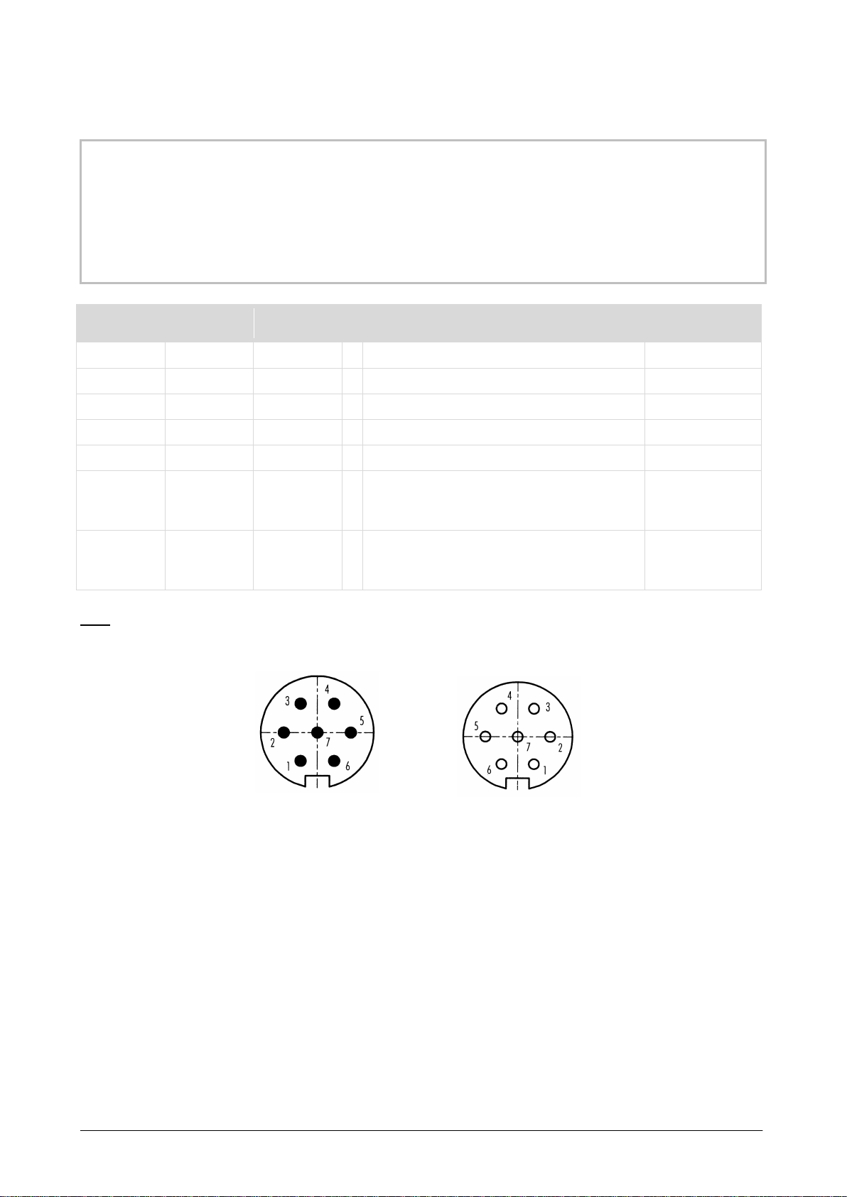
Assignment for 7-pin connector
ATTENTION
When connecting the Infrared Radiation Thermometer
to the Power Supply Unit T24
please note the connection conditions in the manual.
Cores
colors
Code
DIN IEC 757
Plug-in
contacts
Function
green
GN
1
-
analog output
white
WH
2
-
supply voltage (AC or DC)
blue
BU
3
housing
brown
BN
4
+
supply voltage (AC or DC)
yellow
YE
5
+
analog output
pink PK 6
+
+
thermal switch
analog input
digital input note 1
grey GY 7
-
-
thermal switch
analog input
digital input note 1
Note
1: Hardware-Option see Data Sheet (1-1)
7-pin plug connector 7-pin socket-outlet
The load resistors for the analog outputs are:
►for voltage output 0 to 1 V ≥ 10 kOhm,
►for voltage output 0 to 10 V ≥ 10 kOhm,
►for current output 0 to 20 mA ≤ 550 Ohm
►for current output 4 to 20 mA ≤ 550 Ohm
For the signal evaluation, differential inputs are recommended.
3-7
95582944 TECHNICAL SPECIFICATIONS KT15 II
28/06/18e HEITRONICS Infrarot Messtechnik GmbH

3-8
95582944 TECHNICAL SPECIFICATIONS KT15 II
26/01/16e HEITRONICS Infrarot Messtechnik GmbH
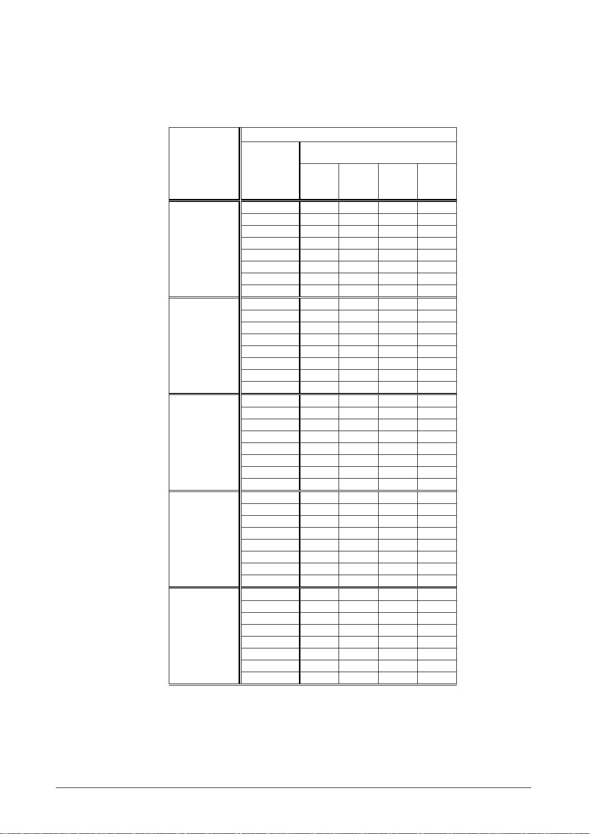
Temperaturauflösung/Temperature resolution KT15.01 II / KT15.02 II
Temperaturauflösung (NET) in ± K (bei Emissionsgrad = 1; σ= 2) für Standardobjektive.
Temperature resolution (NET) in ± K (emissivity-setting = 1; σ = 2) for standard lenses.
** Value is > 20 °C. This setting is not recommended.
Table: Temperature resolution Infrared Radiation Thermometer KT15.01 II / KT15.02 II
Strahler-
temperatur
Radiation
temperature
KT15.01 II
KT15.02 II
Einstell-
zeit
Response
time
Detektortyp
Detector type
Einstell-
zeit
Response
time
Detektortyp
Detector type
A
B
C
G
A
B
C
G
200 °C
5 ms
** ** ** **
5 ms
4.50
16.70
** **
10 ms
** ** ** **
10 ms
3.65
13.55
** **
30 ms
** ** ** **
30 ms
1.35
4.95 12.10
**
100 ms
10.00
** ** **
100 ms
0.55
2.05 4.95 16.45
300 ms
6.70 ** ** **
300 ms
0.35
1.35 3.30 11.00
1 s
2.80 10.30 ** **
1 s
0.15
0.55 1.35 4.60
3 s
1.65 6.20 15.00
**
3 s
0.10
0.35 0.80 2.75
10 s
1.10 4.10 10.00
**
10 s
0.05
0.25 0.55 1.85
300 °C
5 ms
13.30
** ** **
5 ms
1.35
4.85 11.80
**
10 ms
10.80
** ** **
10 ms
1.05
3.95 9.60 **
30 ms
3.95 14.65 ** **
30 ms
0.40
1.45 3.50 11.70
100 ms
1.60 6.00 14.55
**
100 ms
0.15
0.60 1.45 4.80
300 ms
1.10 4.00 9.70 **
300 ms
0.10
0.40 0.95 3.20
1 s
0.45 1.65 4.05
13.50
1 s
0.05
0.15 0.40 1.35
3 s
0.25 1.00 2.45 8.10
3 s
0.05
0.10 0.25 0.80
10 s
0.20 0.65 1.60 5.40
10 s
0.05
0.05 0.15 0.55
500 °C
5 ms
1.45
5.25
12.80
**
5 ms
0.50
1.15
2.60
8.60
10 ms
1.15
4.25
10.40
**
10 ms
0.30
0.90
2.10
7.00
30 ms
0.45
1.55
3.80
12.70
30 ms
0.20
0.35
0.80
2.55
100 ms
0.20
0.65
1.55
5.20
100 ms
0.05
0.15
0.30
1.05
300 ms
0.10
0.45
1.05
3.45
300 ms
0.05
0.10
0.20
0.70
1 s
0.05
0.20
0.45
1.45
1 s
0.05
0.05
0.10
0.30
3 s
0.05
0.10
0.25
0.85
3 s
0.05
0.05
0.05
0.15
10 s
0.05
0.05
0.15
0.60
10 s
0.05
0.05
0.05
0.10
700 °C
5 ms
0.65
1.60
3.80
12.55
5 ms
0.60
0.75
1.20
3.50
10 ms
0.40
1.30
3.05
10.15
10 ms
0.35
0.45
0.90
2.80
30 ms
0.20
0.50
1.15
3.75
30 ms
0.25
0.25
0.40
1.05
100 ms
0.05
0.20
0.45
1.50
100 ms
0.05
0.10
0.15
0.40
300 ms
0.05
0.15
0.30
1.00
300 ms
0.05
0.05
0.10
0.30
1 s
0.05
0.05
0.15
0.40
1 s
0.05
0.05
0.05
0.10
3 s
0.05
0.05
0.10
0.25
3 s
0.05
0.05
0.05
0.05
10 s
0.05
0.05
0.05
0.15
10 s
0.05
0.05
0.05
0.05
1000 °C
5 ms
0.80 0.95 1.55 4.45
5 ms
0.95
1.00 1.05 1.80
10 ms
0.45 0.60 1.15 3.55
10 ms
0.50
0.50 0.60 1.35
30 ms
0.30 0.35 0.50 1.35
30 ms
0.35
0.35 0.40 0.60
100 ms
0.10 0.10 0.20 0.55
100 ms
0.10
0.10 0.10 0.20
300 ms
0.05 0.05 0.10 0.35
300 ms
0.05
0.05 0.10 0.15
1 s
0.05 0.05 0.05 0.15
1 s
0.05
0.05 0.05 0.05
3 s
0.05 0.05 0.05 0.10
3 s
0.05
0.05 0.05 0.05
10 s
0.05 0.05 0.05 0.05
10 s
0.05
0.05 0.05 0.05
3-9
95582944 TECHNICAL SPECIFICATIONS KT15 II
26/01/16e HEITRONICS Infrarot Messtechnik GmbH
Temperaturauflösung/Temperature resolution KT15.21 II
Temperaturauflösung (NET) in ± K (bei Emissionsgrad = 1; σ= 2) für Standardobjektive.
Temperature resolution (NET) in ± K (emissivity-setting = 1; σ = 2) for standard lenses.
** Value is > 20 °C. This setting is not recommended.
Table: Temperature resolution Infrared Radiation Thermometer KT15.21 II
Strahler-
temperatur
Radiation
temperature
KT15.21 II
Einstell-
zeit
Response
time
Detektortyp
Detector type
A
B
C
G
20 °C
5 ms
**
**
**
**
10 ms
**
**
**
**
30 ms
**
**
**
**
100 ms
**
**
**
**
300 ms
**
**
**
**
1 s
**
**
**
**
3 s
**
**
**
**
10 s
**
**
**
**
100 °C
5 ms
** ** ** **
10 ms
** ** ** **
30 ms
** ** ** **
100 ms
** ** ** **
300 ms
** ** ** **
1 s
9.10 ** ** **
3 s
5.45 ** ** **
10 s
3.65 13.50 ** **
200 °C
5 ms
**
**
**
**
10 ms
**
**
**
**
30 ms
12.55
**
**
**
100 ms
5.15
19.00
**
**
300 ms
3.40
12.65
**
**
1 s
1.45
5.25
12.85
**
3 s
0.85
3.15
7.70
**
10 s
0.55
2.10
5.15
17.10
300 °C
5 ms
13.10
**
**
**
10 ms
10.60
**
**
**
30 ms
3.90
14.40
**
**
100 ms
1.60
5.90
14.30
**
300 ms
1.05
3.90
9.55
**
1 s
0.45
1.65
4.00
13.25
3 s
0.25
1.00
2.40
7.95
10 s
0.20
0.65
1.60
5.30
400 °C
5 ms
6.05
**
**
**
10 ms
4.90
18.15
**
**
30 ms
1.80
6.65
16.20
**
100 ms
0.75
2.75
6.65
**
300 ms
0.50
1.80
4.40
14.75
1 s
0.20
0.75
1.85
6.15
3 s
0.10
0.45
1.10
3.70
10 s
0.10
0.30
0.75
2.45
Other manuals for KT15 II
1
Table of contents
Other Heitronics Thermometer manuals


