Heli-Max MX450 XS User manual
READ THROUGH THIS INSTRUCTION MANUAL
FIRST. IT CONTAINS IMPORTANT INSTRUCTIONS
AND WARNINGS CONCERNING THE ASSEMBLY
AND USE OF THIS MODEL.
HMXZ7012 for HMXE0210 V1.0Entire Contents © Copyright 2006
Champaign, Illinois
(217) 398-8970
E-mail: helicoptersuppor[email protected]
INSTRUCTION MANUAL
Rotor Diameter: 27.5 in [700mm]
Weight: 19–22 oz [580–760g]
Length: 25.4 in [645mm]
Height: 9 in [225mm]
Motor: ElectriFly Ammo 28-45-2700kV (GPMG5215)
Heli-Max™guarantees this kit to be free from defects in both
material and workmanship at the date of purchase.This warranty
does not cover any component parts damaged by use or
modification. In no case shall Heli-Max’s liability exceed the
original cost of the purchased kit. Further, Heli-Max reserves
the right to change or modify this warranty without notice.
In that Heli-Max has no control over the final assembly or material
used for final assembly, no liability shall be assumed nor accepted
for any damage resulting from the use by the user of the final
user-assembled product. By the act of using the user-assembled
product, the user accepts all resulting liability.
If the buyer is not prepared to accept the liability associated
with the use of this product, the buyer is advised to return
this kit immediately in new and unused condition to the place
of purchase.
To make a warranty claim, send
the defective part or item to
Hobby Services at this address.
Include a letter stating your name, return shipping address, as
much contact information as possible (daytime telephone number,
fax number, e-mail address), a detailed description of the problem
and a photocopy of the purchase receipt. Upon receipt of the
package the problem will be evaluated as quickly as possible.
WARRANTY
Hobby Services
3002 N. Apollo Dr. Suite 1
Champaign IL 61822
USA
™

INTRODUCTION. . . . . . . . . . . . . . . . . . . . . . . . . . . . . . 2
DECISIONSYOU MUST MAKE. . . . . . . . . . . . . . . . . . . 2
ASSEMBLE THE TAIL. . . . . . . . . . . . . . . . . . . . . . . . . . 3
INSTALL THE PUSHRODS. . . . . . . . . . . . . . . . . . . . . . 4
INSTALL THE SERVOS. . . . . . . . . . . . . . . . . . . . . . . . . 5
INSTALL LINKAGES. . . . . . . . . . . . . . . . . . . . . . . . . . . 6
INSTALL GYRO, ESC & RECEIVER . . . . . . . . . . . . . . . 6
FINAL ASSEMBLY & SETUP . . . . . . . . . . . . . . . . . . . . 7
CHECK THE CONTROL DIRECTIONS . . . . . . . . . . . . . 9
BLADE BALANCING . . . . . . . . . . . . . . . . . . . . . . . . . . 9
ADJUST COLLECTIVE PITCH . . . . . . . . . . . . . . . . . . . 9
SET CONTROL THROWS. . . . . . . . . . . . . . . . . . . . . . 10
ADJUST BLADE TRACKING . . . . . . . . . . . . . . . . . . . 10
RANGE CHECK . . . . . . . . . . . . . . . . . . . . . . . . . . . . . 10
SAFETY PRECAUTIONS . . . . . . . . . . . . . . . . . . . . . . 10
MX400 PARTS LIST . . . . . . . . . . . . . . . . . . . . . . . . . . 11
PARTS DRAWINGS . . . . . . . . . . . . . . . . . . . . . . . . . . 12
PITCH GAUGE . . . . . . . . . . . . . . . . . . . . . . . . . . . . . . 20
The Heli-Max MX450 is a fully aerobatic-capable helicopter,
offering the performance and flying manners of a 60-sized
machine in a smaller, more convenient package.The MX450 is
fully loaded with precision machined aluminum parts for
smooth control without flexing along with a carbon fiber tail
boom and fin set to keep the MX450 light and more agile.The
recommended power system will give you explosive power off
the ground and more than enough power to do tick tocks,
tornado's, chaos's, and much more.
Take care to build straight and true.Misaligned parts will hurt the
helicopter's ability to perform the extreme aerobatics it is
designed for.
For the latest technical updates or manual corrections to
the MX450 visit the Heli-Max web site at
www.bestrc.com/helimax.Open the “Helicopters” link, and
then select the MX450 ARF. If there is new technical
information or changes to this model a “tech notice” box will
appear in the upper left corner of the page.
In the hands of a capable pilot, the MX450 is an impressive
3D performer. But for this helicopter to perform to its full
potential, it must be properly equipped with all the right gear
(servos, batteries, receiver, speed control). There may be
more than one type and brand of radio equipment that can
be used. But based on extensive testing, following is the
equipment we recommend so you can get the most
performance out of your MX450 and assemble it as shown
in this instruction manual.
Transmitter
At a minimum, this helicopter requires the use of a six-channel
helicopter transmitter capable of mixing between the throttle
and collective pitch channels. However, to unleash the full
aerobatic potential of the MX450, you will need a computer
radio capable of at least two sets of throttle and pitch curves.
The Futaba®6EXH radio (FUTK60** or FUTK61**) is an
excellent entry-level radio for use with this helicopter. For more
programming capability, any of Futaba’s higher channel-count
computer helicopter radios will work very well.
Servos
You will need four servos for the MX450.The servos should
weight less than 10 grams apiece, and should have a
minimum torque output of 14 oz-in. A good speed rating is
also important for helicopters, and we recommend that you
choose servos with a speed of 0.12sec/60deg or less. We
recommend the Futaba S3103 (FUTM0037) or S3107
(FUTM0025) for use with this helicopter. Note: The Futaba
S3108 servo will not mount to this helicopter without
modification, and is therefore not recommended.
Receiver
You will need a 6-channel receiver for this helicopter. A
small PCM receiver is strongly recommended for the noise
rejection and failsafe capabilities that PCM offers. We
recommend the Futaba R146iP receiver (FUTL0601) You
will also need a single conversion crystal to use with this
receiver. While most Futaba receivers are sold on high and
low bands, the R146iP is not banded and can use either
high or low band crystals.
Low band (channels 11 – 35) Crystal FUTL62**
High band (channels 36 – 60) Crystal FUTL63**
**Replace the “**” in the order number for the crystals with
the preferred channel number. For example, if you want to
fly on channel 33, order crystal number FUTL6233.
DECISIONSYOU MUST MAKE
CAUTION: Be aware that the MX450 is
operated on the same frequency band as larger R/C
models. If flying your heli within five miles of an R/C
site, there is a real possibility that you could be
operating your model on the same frequency (channel)
as another R/C pilot. If this happens, a crash will
result—with the person flying the more expensive
model suffering the greater loss (and having greater
potential for property damage or injury).The best thing
to do is to join an R/C club and fly at the site where
frequency control measures will be in effect. If you
insist on flying elsewhere, always be aware of your
proximity to R/C flying sites.
INTRODUCTION
2

Gyro Recommendation
We recommend the use of a heading-hold gyro with this
helicopter. The Futaba GY240 gyro (FUTM0809) is an
excellent choice.
Battery
The MX450 requires a 1200-2000 mAh 3-cell Lithium-Polymer
(LiPo) battery capable of delivering 15A of current continuously.
We recommend the ElectriFly™11.1V 2100 mAh pack
(GPMP0841).This battery will deliver approximately 7 minutes
of flight time with the recommended motor and speed control.
Motor
You will need a brushless motor capable of handling 15A of
continuous current, and up to 22A in bursts. The motor
should also have a kV rating of 2500-3000 RPM/V for use
with the included pinion. We recommend the ElectriFly
Ammo 28-45-2700kV (GPMG5215).
Speed Control
A 35-Amp or better brushless electronic speed control
(ESC) is required for this helicopter. We recommend the
Heli-Max 40A Brushless ESC (HMXM3004).
Charger
A charger capable of charging 3-cell (11.1V) LiPo batteries
such as the ElectriFly PolyCharge 1-3-cell LiPo charger
(GPMM3010) must be used. If using another charger, it
must be a LiPo charger or have a LiPo charge mode.Never
charge LiPo batteries with chargers not intended for LiPo
batteries or chargers on NiMH or NiCd settings.
Overcharging or explosion may result. In addition to the
PolyCharge, the ElectriFly Triton™(GPMM3150) and Accu-
Cycle Elite™(HCAP0280) are also suitable chargers.
Battery Charging Leads
Many chargers (including the Triton and Accu-Cycle Elite
listed above) do not include charging leads, but rather have
banana jacks to plug the leads into. If this is the case with
your charger, you will need to purchase a charge lead to
match your battery. For the recommended battery pack, the
correct lead is GPMM3105.
❏1.Install the aluminum horizontal stabilizer and the horizontal
stabilizer bracket onto the tail boom with two 2 x 8mm metal
screws. Do not fully tighten the screws at this time. Be sure to
add a drop of threadlocker to each screw.
❏2. Secure two aluminum tail strut ends and the rear frame
spacer to the frames with two 2x10mm machine screws as
shown.Use a drop of threadlocker to secure each screw.
❏3. Secure two tail strut ends to the aluminum horizontal
stabilizer bracket with 2x8mm metal screws. Use a drop of
threadlocker to secure each screw.
ASSEMBLE THE TAIL
IMPORTANT!
INSPECTYOUR HELICOPTER
Check all screws on the helicopter for tightness. If any
screws are loose, tighten them before flying. If any
machine screw that threads into a metal part is loose, be
sure to secure it with a drop of threadlocking compound.
This check should include the tail blade grip screws,
which will require removal of the tail rotor blades.
3

4
❏4.Insert the carbon fiber tail struts into the aluminum strut
ends. Secure each end with a drop of thin CA.
❏5.Finalize the position of the horizontal stabilizer bracket,
and tighten the horizontal stabilizer screws to hold the
assembly firmly in place. Do not over tighten. Use a drop of
threadlocker to secure each screw.
❏1. Slide the rudder pushrod back through both supports
on the tail boom.
❏2. Screw a ball link onto the threaded end of the
rudder pushrod.
❏3. Connect the ball link to the ball on the tail rotor pitch
control horn. Check to see that the ball link runs freely on the
ball, and loosen it if necessary using the following Heli-MaxTip.
HELI-MAX TIP
How to adjust the fit of ball links.
If a ball link does not twist freely on its ball, squeeze it
firmly with a pair of needlenose pliers
while it is
installed on the ball.
INSTALL THE PUSHRODS

Use this swash plate diagram in your radio for proper setup.
❏1. Locate the 4 aluminum balls and the 4 2mm x 6mm
machine screws. Install the 4 ball links onto all 4 control
horns (AIL, ELE, PIT, RUD).
❏2. Using two plastic servo screw nuts, install the Aileron
servo as shown.With the aileron servo centered, the servo
arm should be completely horizontal with the ball end to the
rear as shown.
❏3. Using two plastic servo screw nuts, install the pitch
servo as shown. With the pitch servo centered, the servo
arm should be completely horizontal with the ball end to the
rear as shown.
❏4. Using two plastic servo screw nuts, install the elevator
servo as shown.With the elevator servo centered, the servo
arm should be completely horizontal with the ball end to the
rear.The output shaft of the servo should point towards the
front of the heli.
❏5. Using two plastic servo screw nuts, install the rudder
servo as shown. With the rudder servo centered, the servo
arm should be completely horizontal with the ball end up as
shown. The output shaft of the servo should point towards
the rear of the heli.
INSTALL THE SERVOS
5
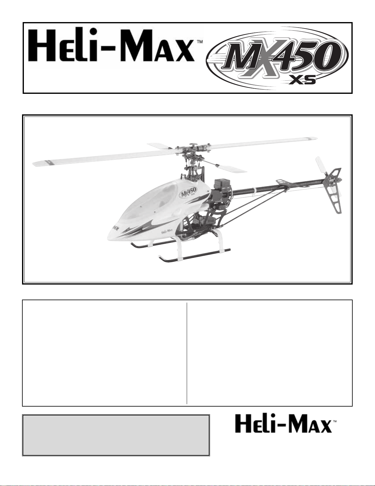
❏6. Locate the 3 control rods and the 6 ball link ends.
1) Pitch (54mm)
2) Elevator (48mm)
3) Aileron (41mm)
All measurements are overall length with the ball links
threaded on to the metal rods.
❏7. Install the Aileron control linkage as shown.
❏8. Install the Pitch control linkage as shown.
❏9.Install the elevator control linkage as shown.Be sure that
the swash plate is level with all the control arms and the servos
are horizontal. If they are not, remove and adjust accordingly.
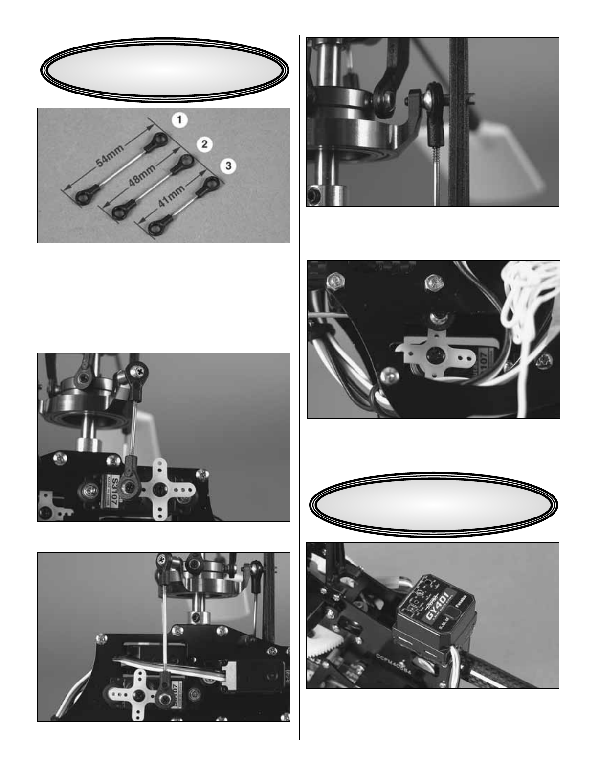
❏10. Install the ball link to the rudder control linkage and
snap it on the ball attached to the control arm.
❏11. Install the Futaba 401 gyro on the top of the frames
as shown with double sided foam tape. Be sure the surface
is clean to get a good bond.An optional mount (HMXE7921)
is available for a more secure mounting, if desired.
INSTALL
GYRO, ESC & RECEIVER
INSTALL LINKAGES
6
❏12.Install the receiver in the bay under the spur gear.Be sure
to keep the receiver towards to rear of the bay as show. Attach
with double sided foam tape or Velcro. Make sure that the
receiver antenna is routed so that it cannot possibly interfere
with the main or tail rotor blades.There are many possible ways
to route the antenna, and you may have to try different methods
to get interference-free operation, but it is essential that the
antenna be constrained from contact with the blades
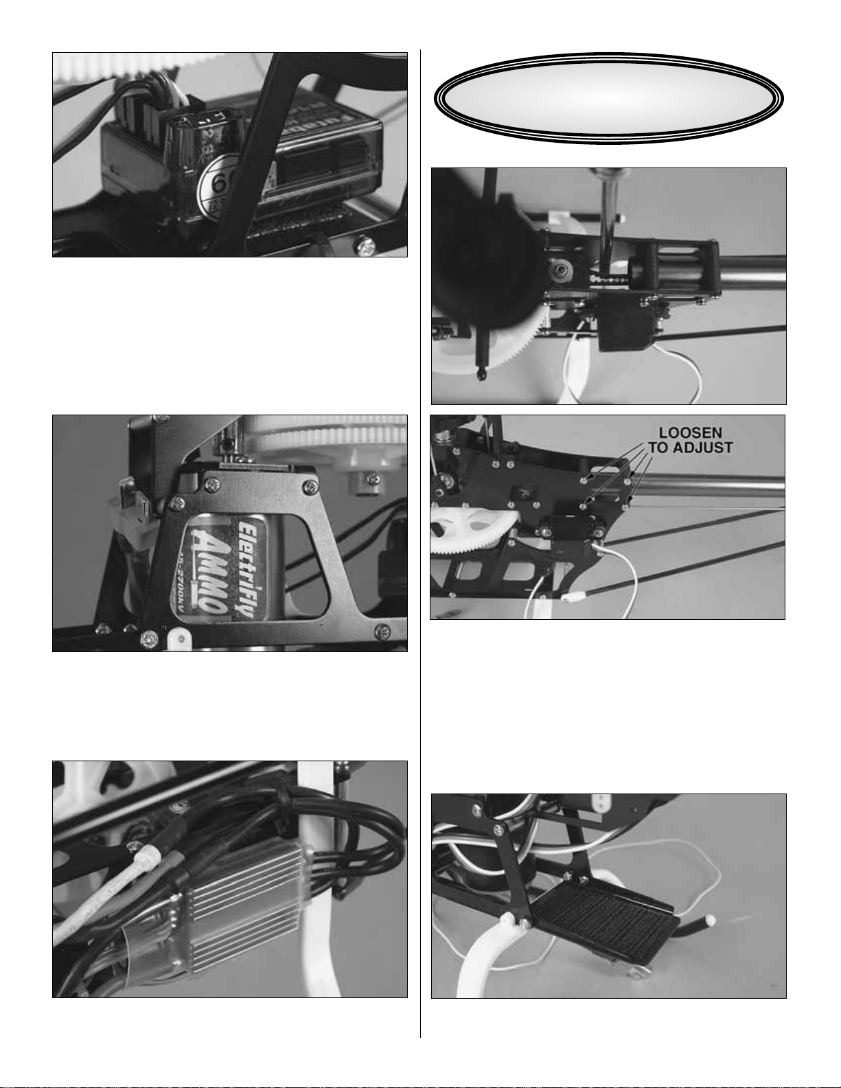
❏13.Install the pinion onto the motor, and install the motor
in the helicopter. Be sure to set the gear mesh properly. This
can be done by pushing the pinion and spur together with a strip
of typing paper between them and tightening the motor screws.
The paper can then be removed by turning the gears to eject it.
❏14. Install the ESC to the bottom of the frames as shown
with hook and loop material or double sided foam tape.
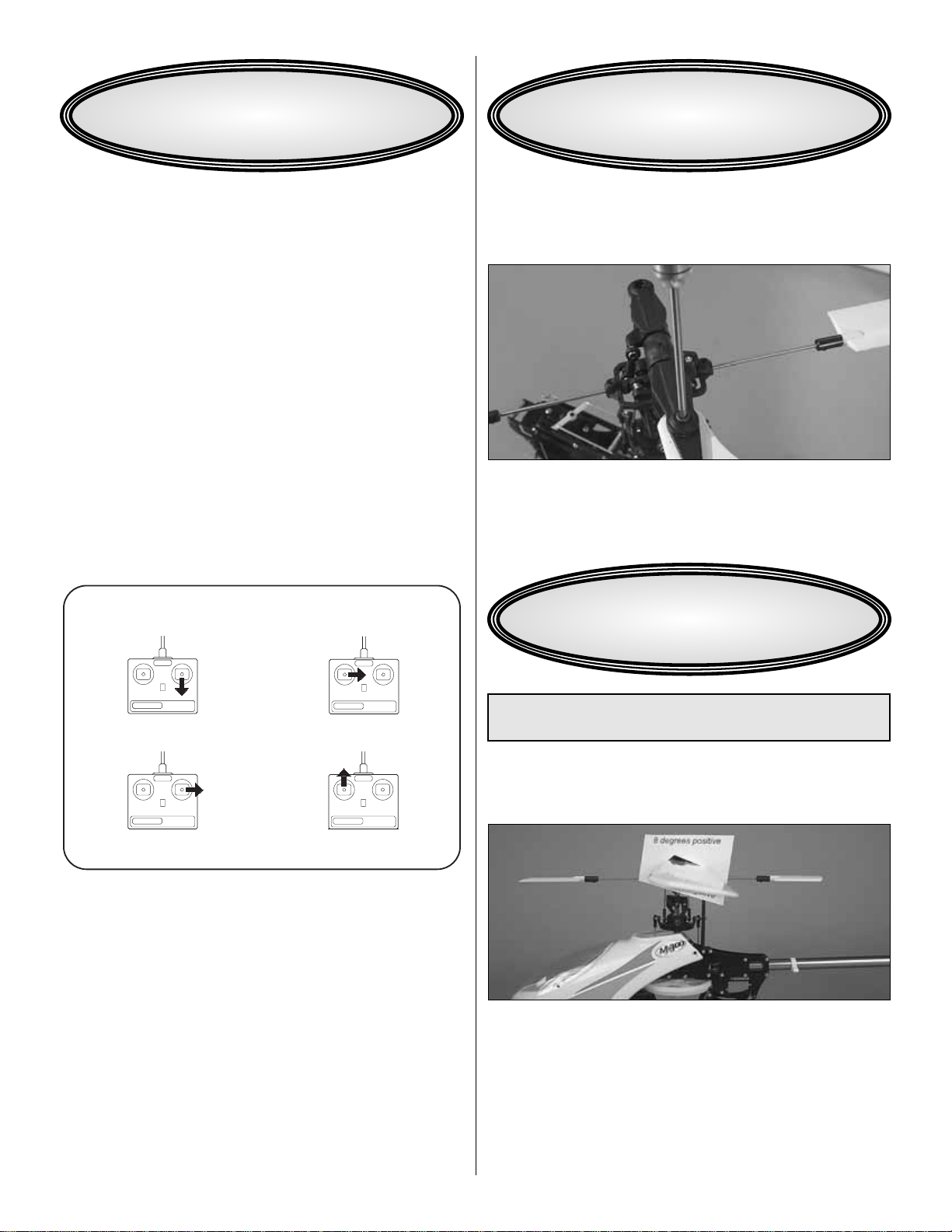
❏1. Check the tail drive belt tension by pressing on one
side of the belt with a screwdriver. With gentle pressure, it
should be possible to push the belt approximately as far as
the picture shows. If you can easily push the belt against
itself, it is too loose.If it does not deflect easily, then it is too
tight.If you need to adjust the belt tension, simply loosen the
screws shown and slide the tail boom in or out. When you
have the tension correct, retighten the screws. Recheck the
rudder pushrod adjustment.
❏2. Attach the hook side of hook and loop fastener to the
battery tray.
FINAL ASSEMBLY & SETUP
7
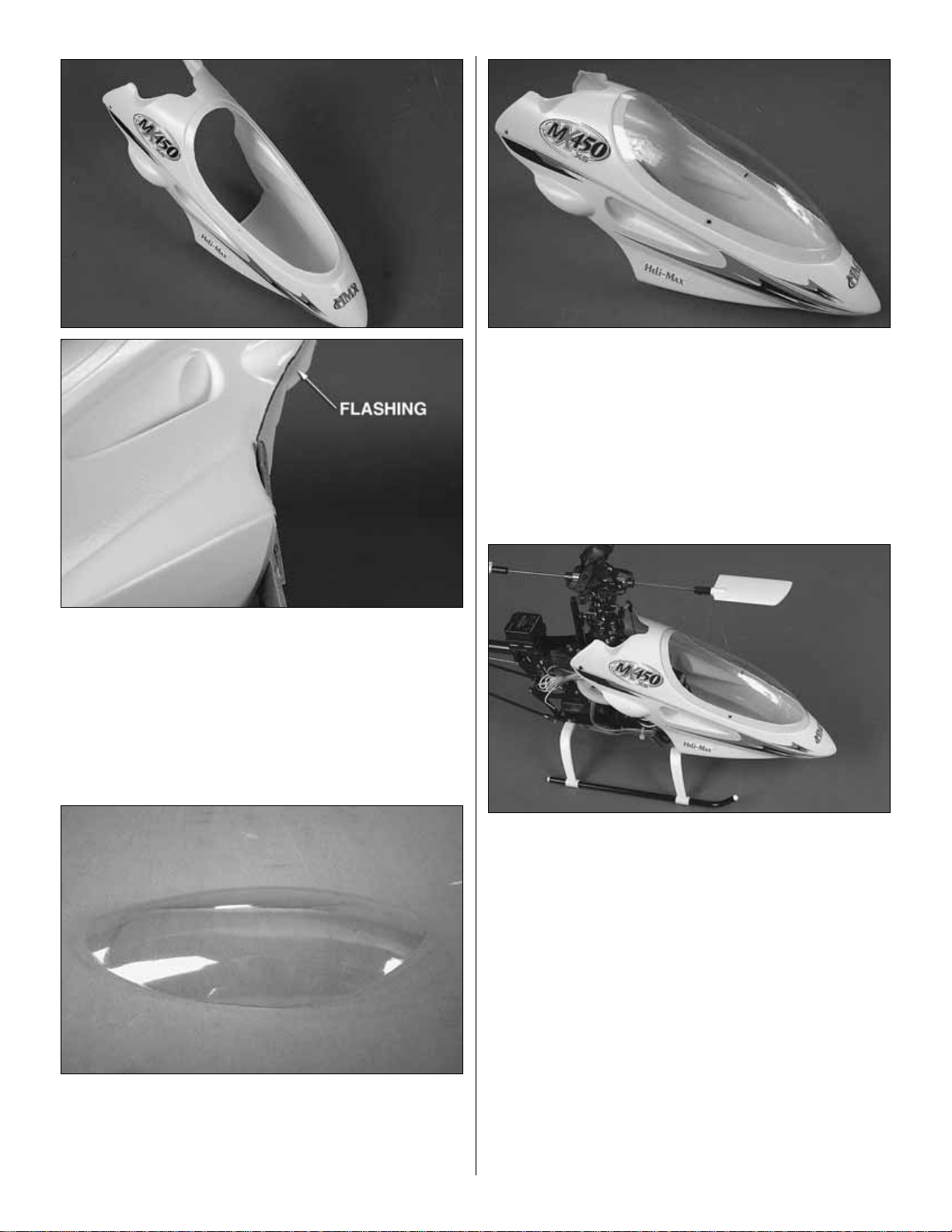
❏3.Cut the window out of the canopy, and trim the flashing
from around the rear opening.
❏4. Cut the clear shield out along the molded-in cut lines.
❏5. Secure the shield to the canopy with the two small
screws packaged with the shield.
❏6. Install the canopy onto the helicopter.
❏7. Apply decals as desired.
8
❏1. Attach the “loop” side of the hook-and-loop material to
the battery. Mount the battery to the battery tray.
❏2. For safety, do not install the main blades while
performing bench setup.
❏3. Lower the throttle stick all the way and turn on the
transmitter.Connect your battery to the ESC.If the ESC has
a BEC switch, turn it on.
❏4. Check all the servos to see if they are centered. Since
you set the center points as you set up the linkages, they
should already be very close. Use the trims or subtrims on
the transmitter to center the controls.
❏5. Make certain that the swash plate and the motor
respond in the correct direction as shown in the diagram.To
operate the motor, you may have to “arm” your ESC. Follow
the instructions that came with your ESC to do this.If any of
the controls respond in the wrong direction, use the servo
reversing in the transmitter to reverse the servos connected
to those controls. Be certain the servos have remained
centered. Adjust if necessary.
❏1. Balance your main blades using the Heli-Max Blade
Balancer (HMXR4855). Do so according to the instructions
that came with your balancer.
❏2. Attach the main rotor blades. The blades should be
tight enough in the grips to hold their position when moved,
but still move easily by hand.
❏1. Cut out the pitch template from the last page of this
manual and slip it over one of the main blades.
❏2.We recommend 8 degrees of maximum collective pitch in
both directions as a starting point.Check to see that the bottom
of the pitch template is level with the flybar at maximum positive
pitch and the top of the template is level with the flybar at full
negative collective pitch.Adjust your linkages or radio endpoints
if necessary to achieve these values.
❏3. Once you are comfortable with the helicopter, feel free to
increase or decrease this pitch value to suit your flying style.
WARNING: Disconnect the motor from the ESC to prevent
accidental startup while performing pitch adjustment.
ADJUST COLLECTIVE PITCH
BLADE BALANCING & INSTALLATION
COLLECTIVE PITCH INCREASES
MOTOR TURNS
RUDDER PUSHROD
MOVES FORWARD
SWASHPLATE TILTS
RIGHT
SWASHPLATE TILTS
BACKWARD
4-CHANNEL
TRANSMITTER
(STANDARD MODE 2)
4-CHANNEL RADIO SETUP
TRANSMITTER
4-CHANNEL
TRANSMITTER
4-CHANNEL
TRANSMITTER
4-CHANNEL
CHECKTHE CONTROL DIRECTIONS
9
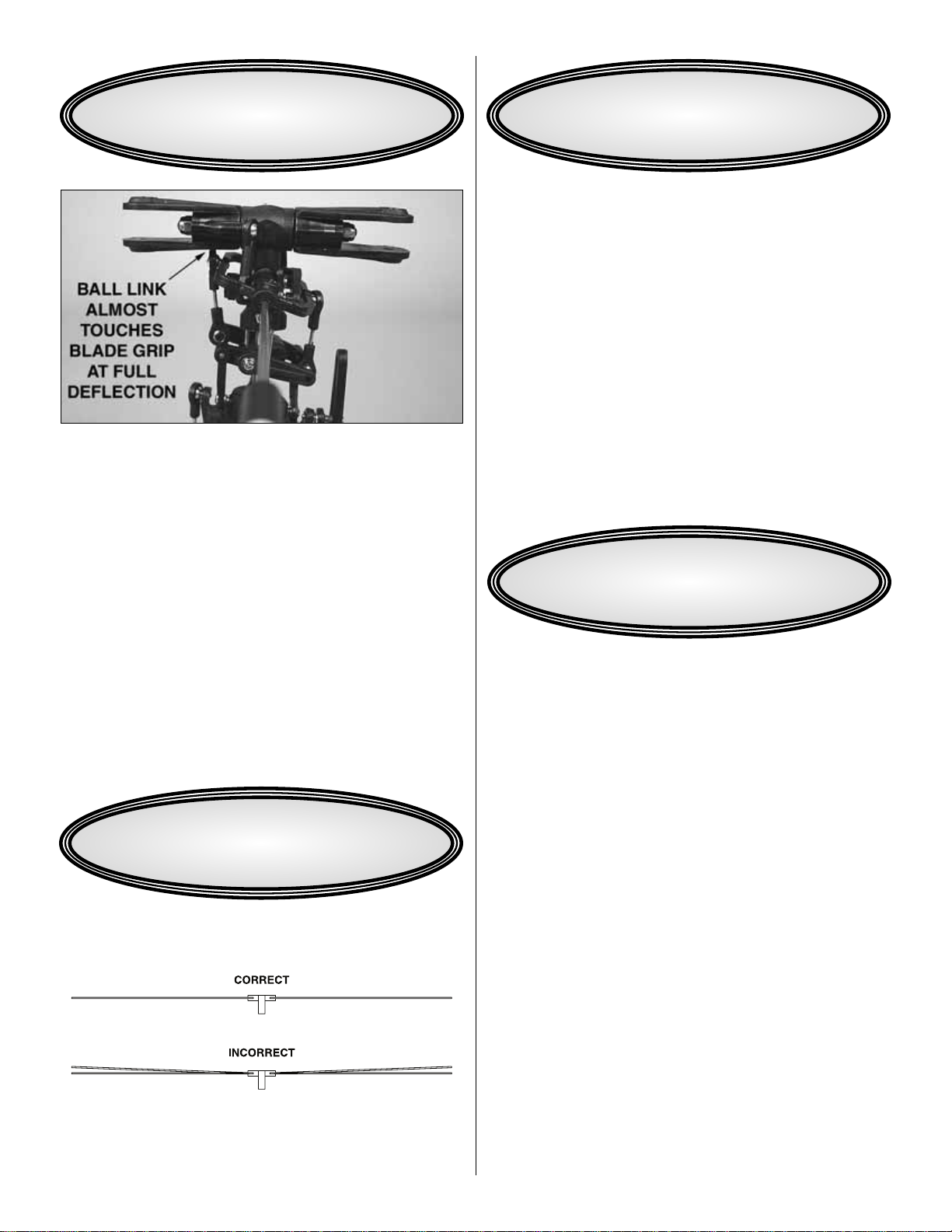
To set rates on the elevator and aileron, check to see that the
control rates are set to maximum for high rates. This can be
verified by checking that the ball link attached to the seesaw is
close to touching the main rotor grips at full input. Check the
elevator rate with the flybar perpendicular to the tailboom, and
check the aileron rate with the flybar parallel to the tailboom.
These maximum deflections work well for high rates, and we
recommend 60% of these values for low rates.
Rudder control throw will be affected by your gyro settings,
and will need to be tuned to suit your flying style.
❏1.Apply the two different colored stripe decals to the tips
of your main rotor blades.
❏2. At zero pitch, bring the main rotor up to speed and
observe whether the rotational planes of the blades are the
same.If they are not, adjust one of the linkages to bring the
blades into the same plane.
Ground check the operational range of your radio before the
first flight of the day.With the transmitter antenna collapsed and
the receiver and transmitter on, you should be able to walk at
least 50 feet away from the model and still have control. Have
an assistant stand by your model and, while you work the
controls, tell you what the servos are doing. Repeat this test
with the motor running at various speeds. If the control
surfaces do not respond correctly, do not fly! Find and correct
the problem first. Look for loose servo connections or broken
wires, corroded wires on old servo connectors, poor solder
joints in your battery pack or a defective cell, or a damaged
receiver crystal from a previous crash.
Failure to follow these safety precautions may result in
severe injury to yourself and others.
Keep your face and body as well as all spectators away from
the plane of rotation of the rotors whenever the battery
is connected.
Keep these items away from the rotors: loose clothing, shirt
sleeves, ties, scarfs, long hair or loose objects such as
pencils or screwdrivers that may fall out of shirt or jacket
pockets into the rotors.
The spinning blades of a model helicopter can cause
serious injury. When choosing a flying site for your MX450,
stay clear of buildings, trees and power lines. AVOID flying
in or near crowded areas. DO NOT fly close to people,
children or pets. Maintain a safe pilot-to-helicopter distance
while flying.
SAFETY PRECAUTIONS
RANGE CHECK
ADJUST BLADE TRACKING
SET CONTROL THROWS
10

11
MX450 XS Parts List
SKU Mfr # DESCRIPTION
HMXE7701....4001-106 ....Stabilizer Blade
HMXE8210....4001-110 ....Auto-Rotation Gear Set
HMXE9713....4001-111 ....Drive Pulley 11T
HMXE9714....4001-112 ....Counter Gear 21T
HMXE8402....4001-113 ....Main Shaft Collar
HMXE7610....4001-114 ....Stabilizer Control Rod
HMXE7614....4001-116 ....Mixing Arm Rod
HMXE7622....4001-120 ....Pitch Rod
HMXE7626....4001-125 ....Control Rod CCPM
HMXE7101....4002-204 ....Anti-Rotation Guide
HMXE7902....4002-205 ....Lower Frame Set
HMXE7910....4002-206 ....Motor Mount Set
HMXE7201....4002-207 ....Battery Mount
HMXE7930....4002-210 ....Skid Set
HMXE7413....4002-211 ....Canopy MX450 XS
HMXE7415....4002-212 ....Windshield MX450 XS
HMXE7906....4002-213 ....Upper Frame
HMXE9710....4003-304 ....Tail Shaft w/Pulley 11T
HMXE9711....4003-305 ....Guide Pulley w/Bearing
HMXE9521....4003-309 ....Tail Rotor Hub
HMXE9501....4003-311 ....Tail Rotor Blade
HMXE9622....4003-313 ....Tail Pitch Lever Set
HMXE9702....4003-314 ....Tail Boom Brace Set
HMXE9715....4003-315 ....Tail Drive Belt (L)
HMXE9623....4003-316 ....Rudder Control Rod (L)
HMXE9422....4003-318 ....Tail Gear Case Plate w/Bearing Alum
HMXE9531....4003-320 ....Tail Pitch Plate Full Set
HMXE9530....4003-321 ....Tail Pitch Plate
HMXE7507....4004-066 ....Decal MX450 XS
HMXZ7012 ....4004-067 ....Instruction Manual MX450 XS
HMXE8312....4011-001 ....Bearing Collar 3x5x4mm
HMXE7315....4011-010 ....Bearing Spacer
HMXE9065....4012-008 ....Radius Arm
HMXE8630....4012-112 ....Spindle Bushing
HMXE8804....4012-019 ....Seesaw (L)
HMXE8635....4013-001 ....Feathering Spindle
HMXE8612....4013-002 ....Anti-Rotation Pin
HMXE8401....4013-003 ....Main Shaft
HMXE7801....4013-006 ....Stabilizer Bar
HMXE8808....4013-010 ....Seesaw Standoff
HMXE8807....4014-001 ....Stand Off
HMXE9066....4016-001 ....Needle Pin 1.5x7mm
HMXE8608....4016-002 ....Center Hub Pin 1.5x18mm
HMXE7903....4021-009 ....Cross member M2x34
HMXE7904....4021-010 ....Cross member M2x16
HMXE7905....4021-011 ....Cross member M2x8
HMXE8013....4021-014 ....Motor Pinion 14T
HMXE8012....4021-016 ....Motor Pinion 13T
HMXE8011....4021-018 ....Motor Pinion 12T
HMXE8010....4021-019 ....Motor Pinion 11T
HMXE8009....4021-020 ....Motor Pinion 10T
HMXE8008....4021-021 ....Motor Pinion 9T
HMXE8007....4021-022 ....Motor Pinion 8T
HMXE8205....4022-008 ....Main Gear 138T (w/One Way Bearing)
HMXE8206....4022-009 ....Autorotation Gear 105T
HMXE7920....4022-013 ....Gyro Mount
HMXE7430....4022-017 ....Canopy Mount
HMXE7381....4022-018 ....Servo Nut Plastic
HMXE8410....4023-003 ....Auto-rotation drive shaft
HMXE9423....4031-001 ....Tail Gear Case Mount Aluminum
HMXE7908....4031-004 ....Cross Member 2 x 10.4mm
HMXE7909....4031-010 ....Cross Member 2 x 4mm
HMXE7623....4043-002 ....Rod End 1.2mm
HMXE7357....4043-007 ....Ball 4.6mm
HMXE7305....4045-001 ....Bearing 2x5x2.5mm
HMXE7306....4045-002 ....Bearing 3x8x3mm
HMXE7307....4045-003 ....Bearing 3x8x4mm
DTXC1547.....4045-004 ....Bearing 5x11x5mm
HMXE7308....4045-005 ....Bearing Flanged 3x8x3mm
HMXE7304....4045-006 ....Bearing Flanged 2x5x2.3mm
HMXE7343....4102-004 ....Pan Head Screw 2x4mm
HMXE7344....4102-005 ....Pan Head Screw 2x5mm
HMXE7345....4102-008 ....Pan Head Screw 2x8mm
HMXE7346....4102-010 ....Pan Head Screw 2x10mm
HMXE7347....4102-012 ....Pan Head Screw 2x12mm
HMXE7348....4102-014 ....Pan Head Screw 2x14mm
HMXE7350....4102-022 ....Pan Head Screw 2x21mm
HMXE7351....4202-007 ....Flat Head Screw 2x7mm
HMXE7352....4202-015 ....Flat Head Screw 2x15mm
HMXE7375....4302-006 ....Tapping Screw 2x6mm
HMXE7353....4402-005 ....Button Head Screw 2x5mm
HMXE7354....4502-006 ....Cap Screw 2x6mm
HMXE7377....4603-003 ....Set Screw 3x3mm
HMXE7355....4702-004 ....Nylon Nut 2mm
HMXE7378....4702-045 ....Nut 2mm
HMXE7379....4703-055 ....Nylon Nut 3mm
HMXE7361....4925-002 ....Flat Washer 2x3.5x0.2mm
HMXE7356....4925-003 ....Flat Washer 2x4x0.3mm
HMXE7380....4925-004 ....E-ring 2.5mm
HMXE7360....4935-005 ....Washer
HMXE7358....5400-115 ....O-ring
HMXE7359....5801-011 ....Washer 3x4.5x0.5mm
HMXE9007....ARK-202.....Swash Plate Aluminum CCPM
HMXE8620....ARK-203.....Top Dome Aluminum
HMXE9421....ARK-204.....Tail Gear Case Set Aluminum
HMXE7907....ARK-208.....Lower Frame Full Set
HMXE9103....ARK-215.....Carbon Tail Boom 345mm
HMXE9625....ARK-218.....Carbon Tail Fin Set
HMXE8611....ARK-220.....Center Hub Set Aluminum
HMXE9057....ARK-221.....Slide Block Aluminum
HMXE8806....ARK-222.....Seesaw w/Bearing Aluminum
HMXE8811....ARK-223.....Stabilizer Control Arm Aluminum
HMXE8821....ARK-224.....Mixing Arm w/Bearing Aluminum
HMXE9061....ARK-225.....Washout Control Arm w/Bearing Alum
HMXE9107....ARK-228.....Horizontal Stabilizer Mount Aluminum
HMXE9703....ARK-229.....Tail Boom Brace End Aluminum
HMXE9062....ARK-230.....Washout Control Set w/Bearing Alum
HMXE8311....ARK-231.....Main Blade Holder w/Bearing Alum
HMXE9524....ARK-232.....Tail Blade Holder w/Bearing Aluminum
HMXE7319....ARK-233.....Bearing Block w/Bearing Aluminum
HMXE7322....ARK-234.....Counter Gear Case w/Bearing Alum
HMXE9104....ARK-235.....Tail Boom Mount Aluminum
HMXE8307....ARK-237.....Main Rotor Blade Fiberglass 325mm
Option Parts
SKU Mfr # Description
HMXE7921....4012-021 ....Upper Gyro Mount Aluminum
HMXM3004....ARK-131.....Brushless ESC w/Heatsink 40A
HMXE7951....ARK-210.....Carbon Frame Full Set CCPM
HMXE8306....ARK-212.....Carbon Main Blade Set 325mm
HMXE7702....ARK-213.....Carbon Stabilizer Blade Set
HMXE9502....ARK-214.....Carbon Tail Blade Set
HMXE7412....ARK-217.....Fiberglass Canopy MX400 Style
HMXE7414....ARK-236.....Fib/glass Canopy MX450 XS Painted
HMXE9109....ARK-238.....Tail Boom Servo Mount Aluminum
HMXE9535....ARK-239.....Tail Pitch Plate Aluminum
HMXE9536....ARK-240.....Tail Pitch Plate Full Set Aluminum
HMXE1007 Mini Blade Holder
HMXE4304 Carbon Main Blades 315mm
HMXE4305 Carbon Main Blades 325mm
GPMP0841 11.1V 2100mAh LiPo Battery
GPMG5215 Ammo 28-45-2700KV Brushless Motor
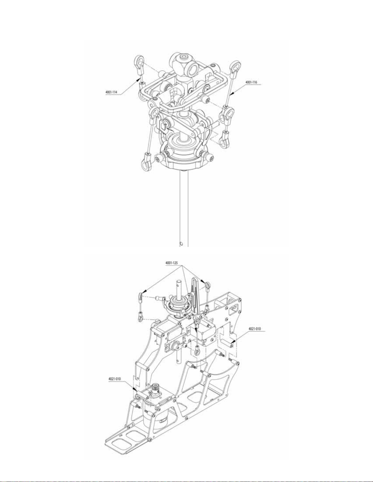
12
4014-001
4013-010
4925-002 ARK-224
4102-010
4045-006
4011-010
4102-004
ARK-222
ARK-223
4043-007
4202-007
4045-001
4603-003
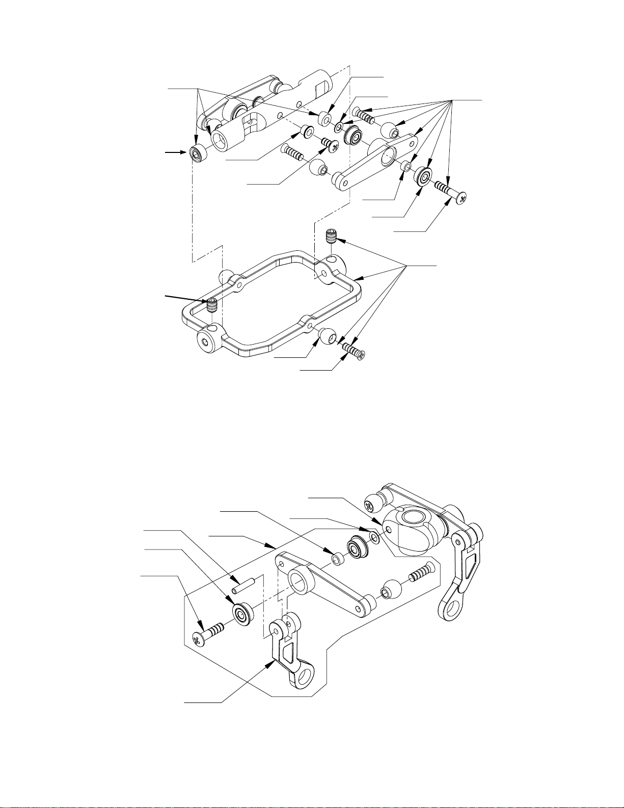
ROTOR HEAD
MIXING LEVERS
ARK-221
ARK-225
4102-010
4045-006
4016-001
4012-008
4925-002
4011-010
13
4001-106
4013-006
4603-003
4001-120
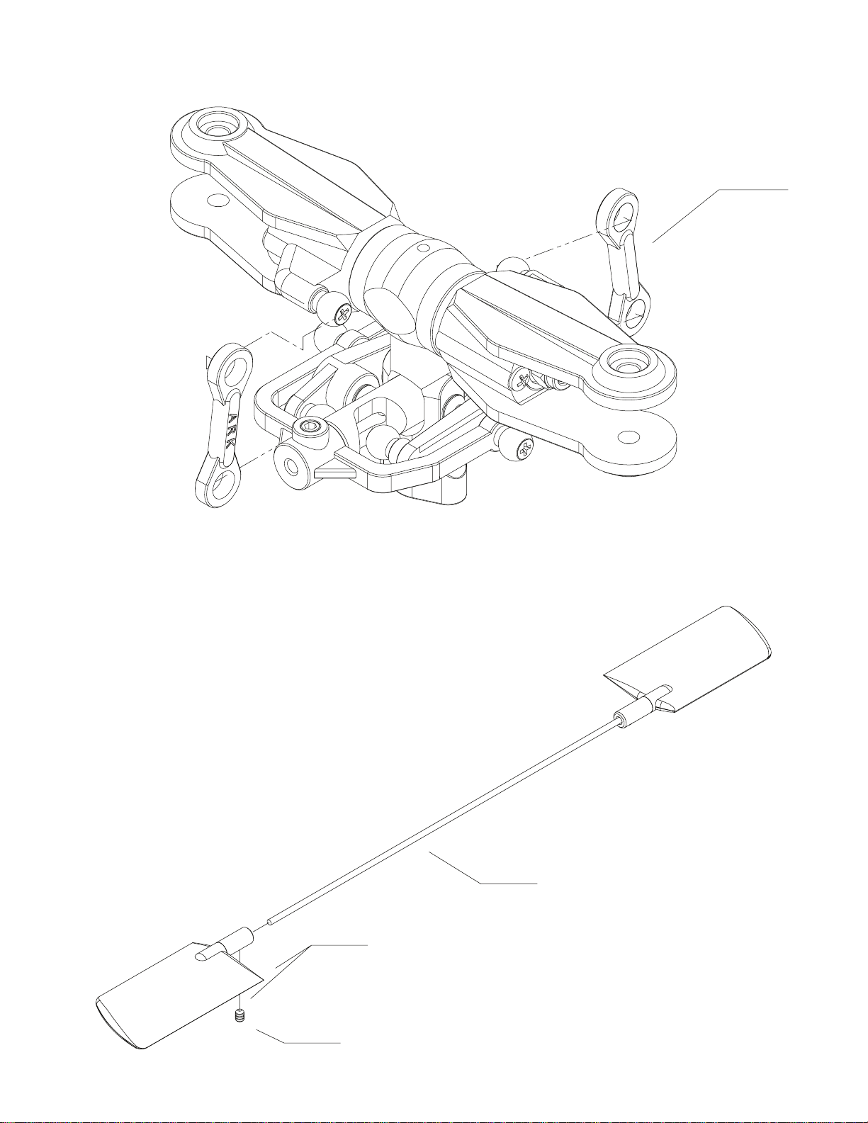
PITCH LINKS
FLYBAR

14
5400-115
4012-112
4013-001
4202-007
4043-007
4045-003
4011-001
4703-055
ARK-220
ARK-203 ARK-231
BLADE GRIPS
BLADE ATTACHMENT
CCPM SWASH PLATE
15
LINKAGES
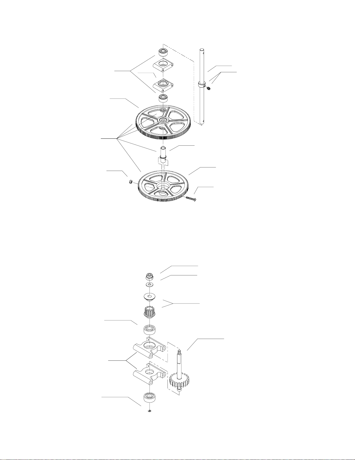
16
4013-003
4001-113
4045-004 ARK - 233
4022-008
4001-110
4023-003
4022-009
4102-012
4702-045
MAIN SHAFT
TAIL DRIVE
4702-004
ARK - 234
4925-003
4001-111
4001-112
4925-004
4045-002

17
4002-213
4102-004
4021-010
4102-022
4013-003
ARK-202
ARK-233
4022-018
ARK-235
ARK-234
4302-006
4702-045
UPPER FRAME
LOWER FRAME

18
4002-210
LANDING GEAR
TAIL BOOM
4003-314
4102-010
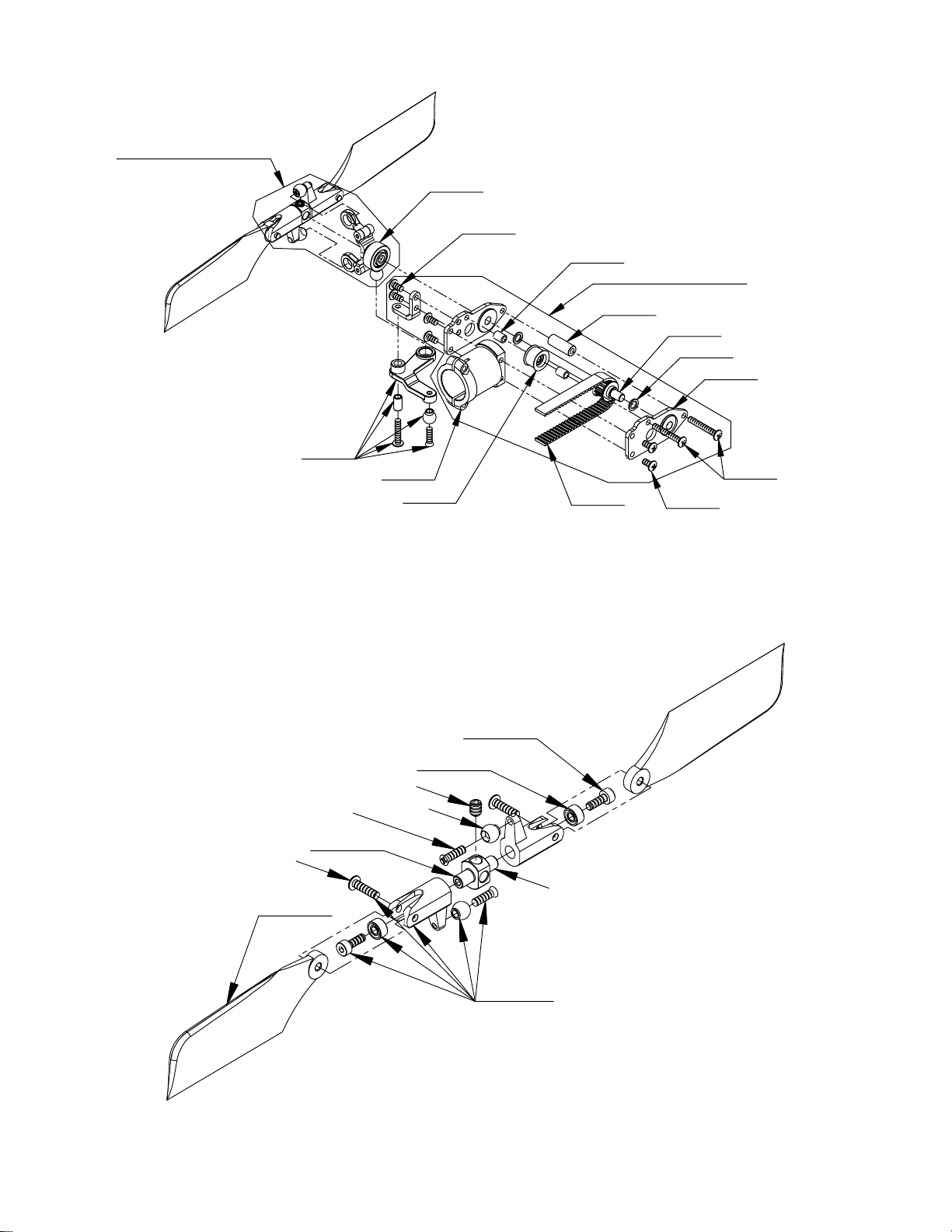
19
4045-001
4502-006
4003-311
4003-322
ARK-232
4102-008
4043-007
4202-007
4003-309
4603-003
TAIL DRIVE GEARBOX
TAIL ROTOR
4003-313
4003-315 4102-004
ARK-204 (w/out 4003-315)
ARK-240 (w/out 4003-311)
4031-004
4031-010
4003-305
4003-318
4031-001
4003-304
4003-318
ARK-239
4102-014
4925-002
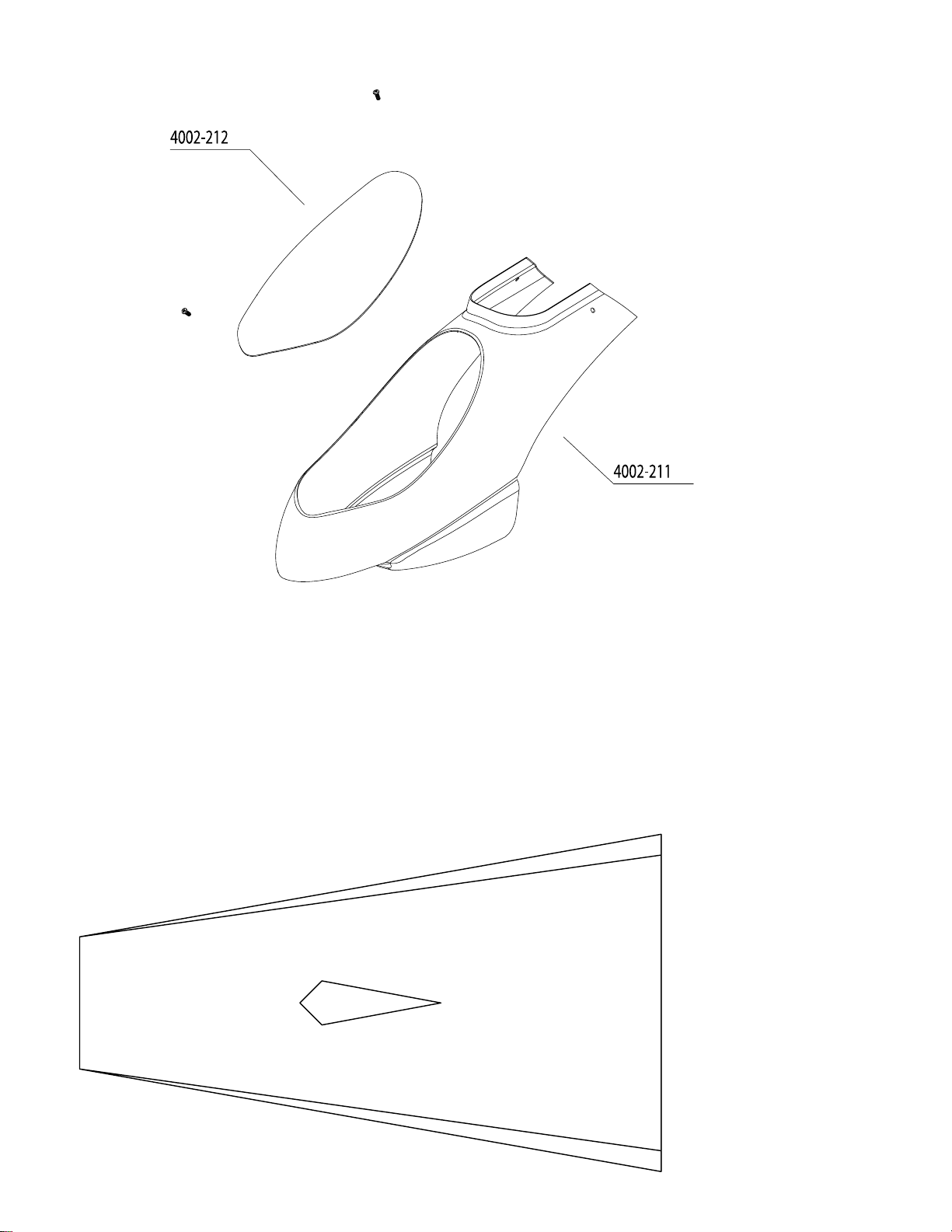
20
CANOPY
PITCH TEMPLATE
10 degrees
8 degrees
10 degrees
8 degrees
Table of contents
Other Heli-Max Quadcopter manuals


