Heli-Max Voltage 500 3D User manual
© 2015 Heli-Max, a Hobbico company. HMXE0864 v1.1
®
Please fully read and understand this manual and the operation and all
safety aspects required of you for the safe operation of this product.
Before use, if you feel this product is not for you please return it to your
place of purchase.
Heli-Max products are to be used by ages 14 and over.
Manual Specications and Description Changes
The instruction manual, warranties and other associated documentation are
subject to change without notice. Hobbico assumes no responsibility for
inadvertent errors to this manual.
WARNING
INSTRUCTION MANUAL

2
INTRODUCTION
Thank you for purchasing the Helimax®Voltage 500 3D. We want the time you
spend with your new R/C quadcopter to be fun and successful, so please
read the entire manual before beginning setup. If for any reason you think this
R/C model is not for you, return it to the dealer immediately. Your dealer cannot
accept returns on any model after final assembly.
FEATURES
●First 500-class reversing motor quad
●High visibility, easy orientation canopy
●Stability mode for safe 3D learning
●Long flight times are possible with 4S, 4,000 mAh batteries
●Efficient 8.9" 3D props provide the lift for incredible aerobatics
●Hybrid Carbon Fiber, G10, and machined aluminum frame
●Compatible with a wide range of 3 and 4S LiPo batteries
●Flight controller compatible with Futaba S.Bus, Standard PWM when
used with S.Bus Encoder, JR XBUS, DSM2, DSMX and DSMJ radios
●25 A reversing brushless speed controls
●1400 kV brushless motors
CONTENTS
●Rx-R Voltage 500 3D
●Spare Props
●Hook & Loop Strip for the Battery
DIMENSIONS
Size: 500 mm (19.7 in) diagonally
Width: 380 mm (14.9 in)
Blade Length: 226 mm (8.9 in)
Weight: 907 g (32 oz) without battery
FLIGHT MODES
The Voltage 3D has two flight modes.
3D Mode – 3D Mode has no limits on the tilt angle and the quadcopter will
not level itself in this mode.
Stability Mode – The Stability Mode will limit the quad to a maximum tilt
angle of 45 degrees. When the stick is centered, the flight controller will level
the quad. This mode makes the Voltage 3D easy to use by pilots that are just
learning 3D. Experienced pilots would assign this mode to a momentary switch
so the quad can be leveled quickly if they encounter a problem while practicing
a 3D maneuver.
3
SETUP
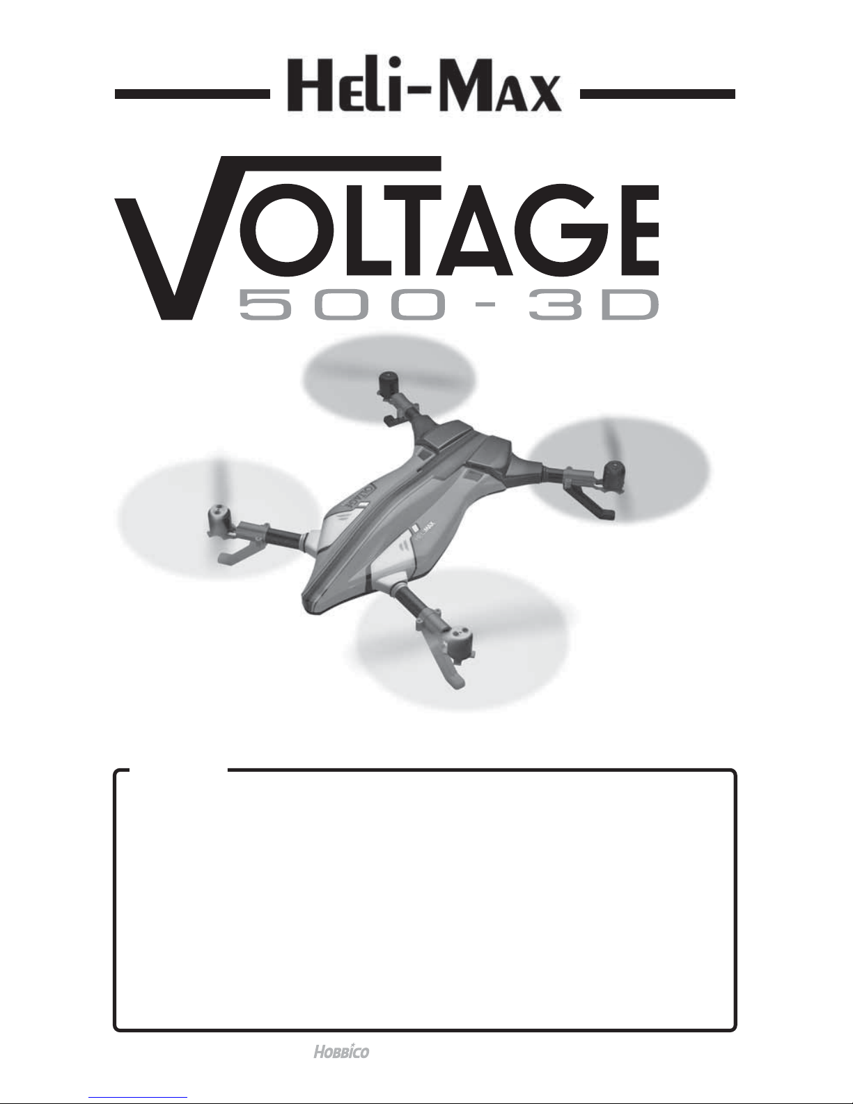
The Voltage 500 3D does
not need any assembly. All
the non-adjustable bolts
have been set to the proper
torque and have thread
locking compound applied
to keep them secure. The
tension of bolts that clamp
the booms should be
checked before each flight
by twisting each motor
mount. If the boom is not
tight, these bolts should be
tightened.
Your transmitter should have at least 5
channels with a 3 position switch for
channel 5. Channel 5 is used to disarm
the motors and select the 3D or stability
flight modes. The setup below is typical
for most Futaba and Tactic transmitters.
Most Spektrum radios can use a similar setup by using the channel name and
not reversing the throttle channel. A small receiver can be mounted on the top
plate and still fit below the canopy. We recommend mounting the receiver at
the back of the frame between the rear tube holders.
CHANNEL ASSIGNMENTS
MODEL TYPE: Airplane
Channel
Aileron
Elevator
Throttle
Rudder
Gear
Direction
normal
normal
reverse
normal
normal
Dual Rates
80/100
80/100
80/100
Expo
-
30/0
-
30/0
-
30/0
End Points
10 0 / 10 0
10 0 / 10 0
10 0 / 10 0
10 0 / 10 0
10 0 / 10 0
SWITCH ASSIGNMENTS - Ch 5
Gear
Gear
Gear
-
100 %
0%
+100 %
Motors Disarmed
3D mode
Attitude mode
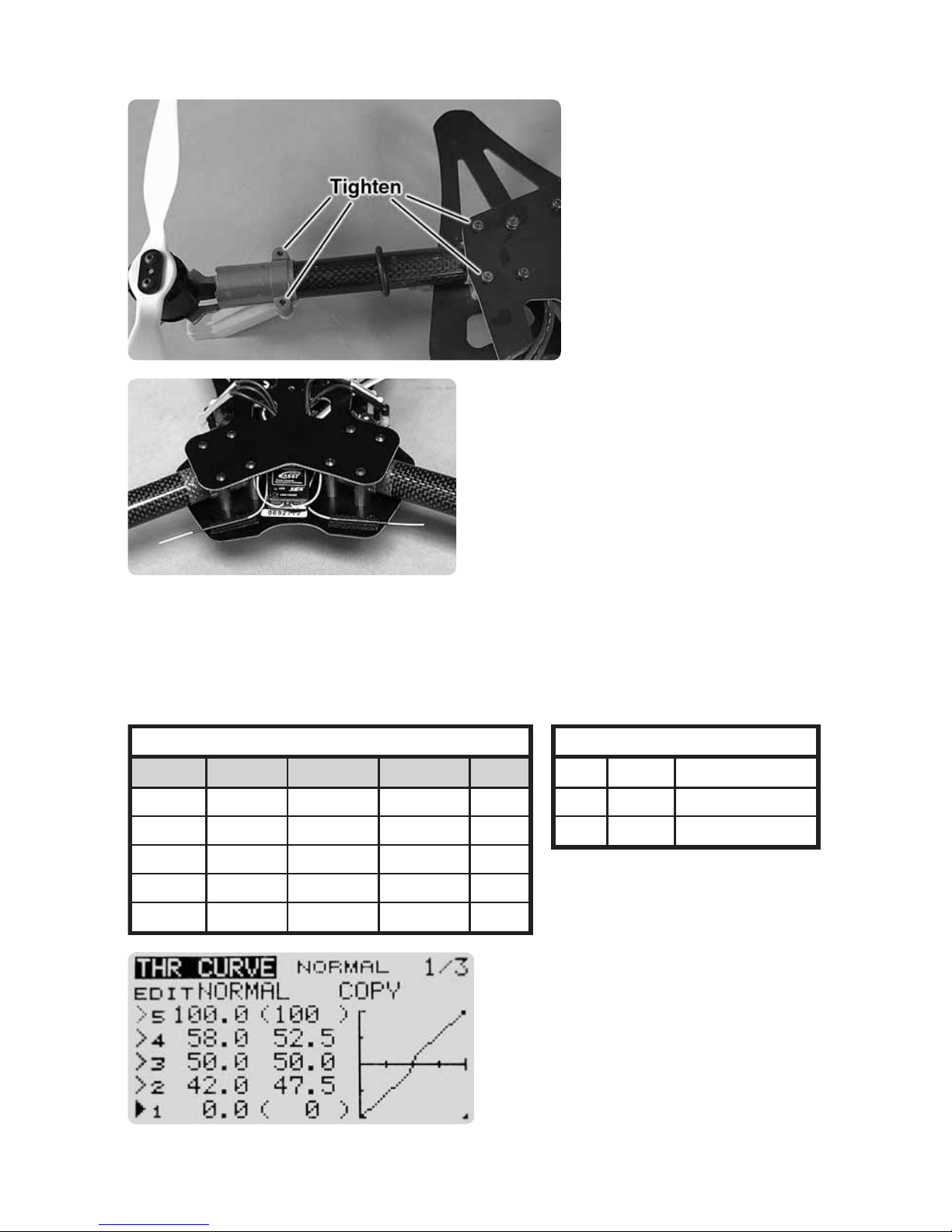
Make sure that your throttle curve is
linear. The motor’s transition time from
forward to reverse can be reduced
by setting points a few % above and
below midstick, making the throttle
curve as steep as possible between
those points.

4
Before testing your setup, remove the props from the motors. Turn on the
transmitter and connect the battery to the Voltage 500 3D. Use the LED codes
on the Flight Controller to verify that Gear switch can select the Motor Disarm
mode and the two flight modes.
Next, arm the motors by selecting one of the flight modes and advance the
throttle so it is at or just above midstick. When the motors start to spin, hold
the throttle until the motors speed up and slow down to idle. Now advance
the throttle to speed up the motors and move the right stick in any direction.
The motors on the opposite side of the quad will speed up so they can tilt the
quadcopter in the desired direction. When you have made sure that the quad
is responding to the controls correctly, move the Gear switch back to the
Disarm position to stop the motors.
NOTE: If your transmitter has a Throttle Hold Gyro setting in the heli mode,
setting the gyro to
-
100% on channel 5 will allow the throttle hold switch to
disarm the motors. Setting the Idle-up and normal mode gyros to 0 and +100%
on channel 5 will allow the idle-up switch to be used to the select the 3D or
Stability flight modes. Using the separate switch to arm and disarm the motors
eliminates the possibility of shutting off the motors while changing flight modes.
FLIGHT CONTROLLER
ESC Connector
S.Bus or X.Bus Connector
Orientation Arrow
ESC Connector
4 Pin Connector (factory use only)
Reset Button
ESC Connector
ESC Connector
Satellite Receiver Connector
Satellite Receiver Connector
The Flight Controller (FC) has an orientation arrow that must point towards the
front of the Voltage 500 3D.
ESC Connectors
There are 4 connectors for the speed controls located on the lower side of
the FC.
Reset Button
The button in the center of the FC should be pressed to reset the FC if it locks
up while uploading new firmware.

5
FLIGHT CONTROLLER LED CODES
Color
Steady Green
Rapid Flashing Green
Slow Flashing Green
Red
Indicator
Motors Disabled
3D mode
Attitude mode
Controller not receiving
TX signal
VOLTAGE 3D APP
The Voltage 500 3D has an
app that can also be used
to verify that the controls
and switches are setup
correctly. This app must be
used to change the gyro
settings in the flight
controller. A mini USB
cable (not included) will be
needed to connect the
Voltage 500 3D flight
controller to your PC.
The latest version of the Voltage 3D app, the manual and the Windows USB
driver can be found at www.helimax-rc.com
Download and unzip the driver files. Click on the Installer application to install
the drivers on your computer.
Download the latest version of the Voltage 3D app and install it on your PC.
WARNING: Before using the app, remove the propellers from the motors.
The motors can be armed and operated while the flight controller is
connected to the Voltage 3D app.
Turn on the transmitter and connect a flight battery to the Voltage 500 3D.
When you see a steady green LED, connect the USB cable to your computer
and the USB port on the flight controller.
To test the setup, move each control stick in both directions to verify that the
controller is receiving the signal on the proper channel and is moving in the
correct direction. Also make sure that the switches for the motor disarm and
flight modes are responding properly.

6
These settings were
tested with 3S and
4S batteries.
TIP: While removing the USB cable from the flight controller, push down on
the controller to keep it from moving. If any of the o-rings on the mounting
posts are lost, the controller may come loose in flight.
FAILSAFE
If your transmitter can set values for all the channels for failsafe, set channels
1-4 to a midstick value and set channel 5 to
-
100% which will stop the motors.
For transmitters that only set the failsafe on the throttle channel, set the throttle
to 50%. (midstick)
Be sure to remove the props before testing the failsafe operation.
BATTERIES
The Voltage 3D can use a 3 cell or 4 cell LiPo between 2200 mAh and 4000 mAh.
The flight time can be as long as 12 minutes with a large battery and a very
mild flying style. The flight controller does not have a low voltage cutoff to
protect the LiPo from damage. The LEDs on the bottom of the speed controls
will start flashing when the battery is at 10.2V for a 3S battery and 13.6V for
a 4S LiPo. For your first flight, set a timer for 3 minutes. If the LEDs are not
flashing at the end of the flight, increase your flight time a few seconds. If the
LEDs on the speed controls are flashing at the end of the flight, the timer
setting should be reduced by at least 10 seconds to protect the battery.
WARNING: Your battery life will be shortened and the
battery can be damaged any time the voltage drops below
3.25 V/cell. Charging a LiPo battery that is damaged in
any way can pose a fire hazard.
We recommend using a voltage monitor/alarm that plugs into the battery’s
balance connector and will sound an alarm when the battery voltage gets low.
PROP INSTALLATION
There are 2 “A” props, one of each
color. These props spin CCW.
There are 2 “B” props, one of each
color. These props spin CW.
A little thread locking compound
should be used on the screws
that hold the props on the motor.
FACTORY DEFAULT GYRO SETTINGS
70
65
70
Aileron/Elevator Gain
Aileron/Elevator Damping
Rudder Gain

7
MOTOR ARMING
Set the transmitter so the motors are disarmed.
Place the Voltage 3D on a level surface and connect the battery. If the quad
is not level when powered up, it may drift when the sticks are centered.
After the speed controls have chimed twice, pause, and then chime again,
select the desired flight mode and arm the motors if the transmitter is using
throttle hold.
Advance the throttle to just above midstick and wait for the motors to start
spinning. When they speed up and slow down to idle, the Voltage 3D is
ready to fly.
WARNING: If your transmitter is set up to use the same switch for disarming
the motors and selecting the flight mode, be careful when switching from
Stability Mode to 3D Mode while in flight. If the switch is moved to the
motor disable position, the motors will stop.
TROUBLESHOOTING
Motors will not arm
Make sure that the throttle trim is centered and the throttle is at or just above
midstick.
Check the throttle curve for offset. The throttle should be at 0 when the stick
is centered.
Motors spin but the quadcopter will not take off
If parts have been replaced, check the motor
wires on each ESC. The color of the wire
should match the colors on the socket for
the front right and rear left ESC.
On the front left and rear right ESC, the
colors on two of the wires will not match
the sockets.
Make sure that the props are installed correctly and the motors are spinning
in the correct direction. Please refer to the diagram in the Prop Install section.

8
SPARE PARTS
1 HMXE2402 Lower Frame
2 HMXE2401 Upper Frame
3 HMXE2403 CF Booms (4)
4 HMXG2405 Brushless Motor
5 HMXE2407 8.9" 3D Prop Set (4)
6 HMXM2410 Voltage 500 3D Flight Controller Set
7 HMXE2412 CNC Tube Holder 19 mm
8 HMXE2413 Voltage 500 3D Red Body
17 HMXE2422 Voltage 500 3D Clear Body
9 HMXE2416 Landing Gear Red
10 HMXE2417 Landing Gear Black
11 HMXE2418 Motor Mount
12 HMXM2414 Voltage 500 3D ESC
13 HMXE2419 Screw Set
14 HMXE2415 O-ring Set
15 HMXE2420 Prop Bolts
16 HMXE2421 Velcro Battery Strap
HMXE2411 Sbus Encoder Cable
EXPLODED VIEW
1
2
3
3
3
4
44
4
5
5
5
6
7
7
8
17
9
10
11
11
11
12
13
13
13
13
9
13
13
14
14
15
15
15
16
© 2015 Heli-Max
,
a Hobbico com
p
an
y
.HMXE0864
Table of contents
Other Heli-Max Quadcopter manuals


