HELI gieen Series Installation and operating instructions

FOREWORD
The G series 1.6-1.8t electric narrow aisle reach truck is new offering of HELI to
meet market needs. The new series is designed on the base of the advantages of some
reach trucks made by domestic and foreign manufacturers. It has modern designed
appearance, simple structure, comfortable operation, and superior maneuvering
performance. It is mainly used for goods handling and stacking indoor with narrow
aisle such as factory, warehouse, supermarket and so on.
The series truck has streamline appearance and ergonomic designed cab; AC
type lifting, travelling and steering control systems are applied on the truck; three
phase AC type motors are assembled on the truck; the operator has wide view with
three stage full free high lifting mast; EPS electric powered steering system makes
steering easy; electromagnetic brake of the front wheel and energy regenerating
technology of AC motors effectively reduce noise and improve truck comfort and
reliability; the truck has precise and stable operation through superior motor, battery,
multi function LCD meter and DC-DC pressure converter; buffers at the upper and
lower limit position and during mast lifting and lowering effectively reduce working
noise and realize stable moving; with CAN bus technology, the truck is more reliable;
lifting height display and pre-selector are optional. The truck has the characteristics of
good performance, easy operation, flexible steering, reliable brake, good power, low
noise and no pollution and so on.
This manual states the trucks’ specification, operation, maintenance, service, main
assemblies’ constructions and working principles so as to help operators to use the
truck correctly and attain the highest function. It is necessary to read over the manual
before operating the trucks.
The rules and notices in the manual should be abided seriously by all of the
relative people to enable these trucks in optimized working state for long period and
bring the highest efficiency.

The graphic illustrations such as pictures, drawings and parts characters and so on
in the manual are not in real proportion because of the limit of space, so you can not
get the size and weight accurately from the graphic illustrations which are to describe
the correct operation methods of the devices and parts.
This manual might not correspond with the actual condition because of the
improving of our products. Our products are subject to improvements and changes
without notice.

CONTENTS
I. Safety Instructions of Operation and Driving……………………………………..1
II. External View of Reach Truck……………………………………………………5
III. Main Specifications………………………………………………………………6
IV. Construction and Principle of Reach Truck………………………………………7
4.1 Transmission system………………………………………………………..7
4.2 Rear axle………………………..……………………………………………9
4.3 Steering system……………………….……………………...…………11
4.4 Supporting wheel assembly…………….……………………………..12
4.5 Brake system ……………….…………………………………………14
4.6 Hydraulic system……………….……………………………………...….17
4.7 Body system……………..……………………………………………….29
4.8 Lifting system……………………………………………………….……31
4.9 Electric system………………………………………...……………………53
V. Troubleshooting…………………………………………………………………..93
5.1 Transmission system………………………………………………………93
5.2 Steering system…………………………………………………………….93
5.3 Parking brake system………………………………………………………93
5.4 Hydraulic system…………………………………………………………..94
5.5 Electric system……………………………………………………………95
VI. Maintenance……………………………………………………………………96
VII. Others………………………………………………………………………….99
7.1 The size and weight of the main takedown parts of the truck……………..99
7.2 Mast disassembly…………………………………………………………. 99
7.3 Overhead guard disassembly………………………………………………99
7.4 Vibration specification…………………………………………………...100

1
I. Safety Instructions of Operation and Driving
1. Drivers and equipment keepers should keep “safety first” in mind and operate
according to the operation and service manual.
2. Transporting
Pay attention to the following instructions before transporting the forklift with
containers or trucks:
2.1 Take the working device backward, turn off the battery and pull the parking
brake;
2.2 Hang up the forklift according to the decal. It is not allowed to hang the mast
or get into or out the truck directly by platform.
2.3 Fix the overhead guard and mast with wire and wedge wheels securely when
delivering the forklift.
3. Storage
3.1 Lower the forks to the floor;
3.2 Turn off the key switch and emergency switch, place all operating levers in
neutral and pull out the plug from the battery set.
3.3 Pull the parking brake;
3.4 Put up the wheels and recharge the battery once every month when the
forklift is lying by for a long time.
4. Preparations for start
4.1 Read the manual carefully to get familiar with the meters, operating levers,
construction and functions of the forklift before driving. Please see figure 1. The
drivers must have license.

2
Figure 1-1 Layout of instrument and operating mechanism of standard model
1. Brake pedal (pedal safety switch) 2. Steering wheel 3. Key switch
4. Display instrument 5.6.Automatic centering switch 7. Front lamp
8. Integrated knob 9. Emergency button
4.2 Check all the instruments for normal function;
4.3 Check the polyurethane solid tyre;
4.4 Check all operating switches and pedals;
4.5 Check the battery for output voltage, specific gravity and state of battery
capacity;
4.6 Check all of the connectors and plugs in the electric system for reliable
contact and accelerator pedal for effectiveness and flexibility;
4.7 Check hydraulic oil, electrolyte and brake fluid for leakage;
4.8 Check main fixing parts for tightness;
4.9 Make the trial of the mast for lifting, lowering, forward and backward tilting
and the truck for steering and braking.

3
5 Precaution in driving
5.1 Do not grasp the steering wheel when getting on the truck.
5.2 Pay attention to the state of mechanical, electrical, hydraulic system and
MOSFET speed adjuster.
5.3 Turn on the key switch and pull up the emergency switch, then push forward
or pull backward integrated knob to keep proper acceleration.
5.4 Read the electric energy on the meter and charge the battery or change a full
one when the capacity of the battery is less than one LED.
5.5 Do not over load. Insert the forks to pallet correctly and do not hand
off-center loads.
5.6 Starting, steering, driving, braking and stopping should go well. Slow down
when steering.
5.7 Do not stand under the fork and on the fork when lifting the fork.
5.8 Do not operate the levers or attachment out of the seat. Do not stand on the
telescopic working device in case of danger of mis-operating the telescopic levers.
5.9 Tilt the mast forward or backward completely or ensure the operating levers
back to neutral position when the mast is at the highest position.
5.10 When releasing operating levers suddenly during mast lowering, the mast
will act after a short time.
5.11 When travelling with load, tilt the mast backward, retract the working
device and keep the load as low as possible. Do not travel or steer when lifting the
mast.
5.12 When driving, be careful of the passersby, obstacles and rough road, and
make sure there is enough clearance between the mast and the entrance.
5.13 Do not brake suddenly.
5.14 Before leaving the forklift truck, lower the fork fully, place levers in neutral,
turn off the battery and pull the hand brake.

4
5.15 Do not adjust the pressure of the control valve and safety valve which has
been adjusted well in our company as will.
5.16 Check the chain regularly.
5.17 According to the measurement method specified in JB/T3300, the maximize
noise at the outboard of the truck should be no more than 75dB (A).
6. Charging
6.1 Obey the stipulations strictly in operation instruction for battery when first
charging or recharging.
6.2 if the output voltage of the battery is reduced to 41V /31V, or the voltage of
anyone lower than 1.7V or the meter alarms, the truck should stop working
immediately until the battery is replaced or charged.
6.3 When charging, often check specific gravity, liquid leveL and temperature of
the electrolyte.
6.4 Charge the battery as soon as possible (in 24 hours) after working. Do not
undercharge or overcharge in case of a damage to the battery.
6.5 Please refer to the battery operation and service manual for charging method
and maintenance.

5
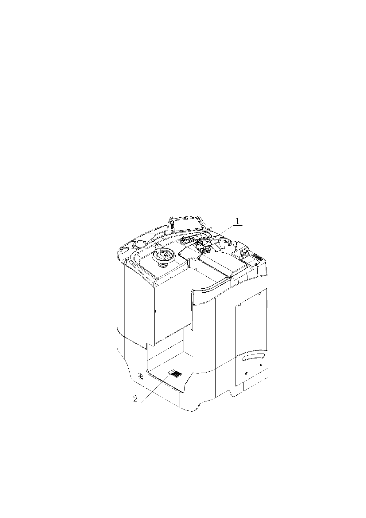
II. External View of Reach Truck
Figure 2-1 External view of reach truck

6
III. Main Specifications
Characteristic
Model
CQD16X1
CQD18X1
GB2R
GB2R
Driving type
Stand-on type
Stand-on type
Battery voltage/capacity
V/Ah
36/775,48/500
36/930,48/560
Battery weight
kg
800
940
Parking brake
Electromagnetic brake
电磁制动
Wheels
Tyre type
Polyurethane
聚氨酯
Load wheel
mm
Ф127x99
Ф127x99
Drive wheel
mm
Ф330x140
Ф330x140
Auxiliary wheel
mm
Ф178x76
Ф178x76
Dimensions
Standard lifting height
mm
5330
5330
Mast height, lowered
mm
2526
2526
Tilting angle(Fwd/Bwd )
º
3/4
3/4
Fork length/width/thickness
mm
920x100x35
920x100x35
fork side shift amount
mm
±50
±50
Truck length
(without fork)
mm
1815
1865
Truck width
mm
1090
1090
Overhead height
mm
2320
2320
Min.underground
clearance (at mast)
mm
60
60
Front overhang
mm
318
318
Reaching forward distance
mm
600
600
Wheel base
mm
1407
1457
Min. steering radius
mm
1695
1745
Right angle stacking width
mm
2817
2832
Performance
Travelling speed, w/o load
km/h
11.8/10.5
11.8/10.5
Lifting speed, w/o load
m/s
0.51/0.33
0.51/0.33
Lowering speed, w/o load
m/s
0.5/0.5
0.5/0.5
Front reaching speed, w/o load
m/s
0.15/0.11
0.15/0.11
Rated capacity
kg
1600
1750
Load center
mm
600
500
Max. gradeability, w/o load
%
15/10
15/10
Motors
Driving motor power
kw
7
7
lifting motor power
kw
15
15
Steering motor power
kw
0.6
0.6

7
IV. Construction and Principle of Reach Truck
4.1 Transmission system
4.1.1 Working principle
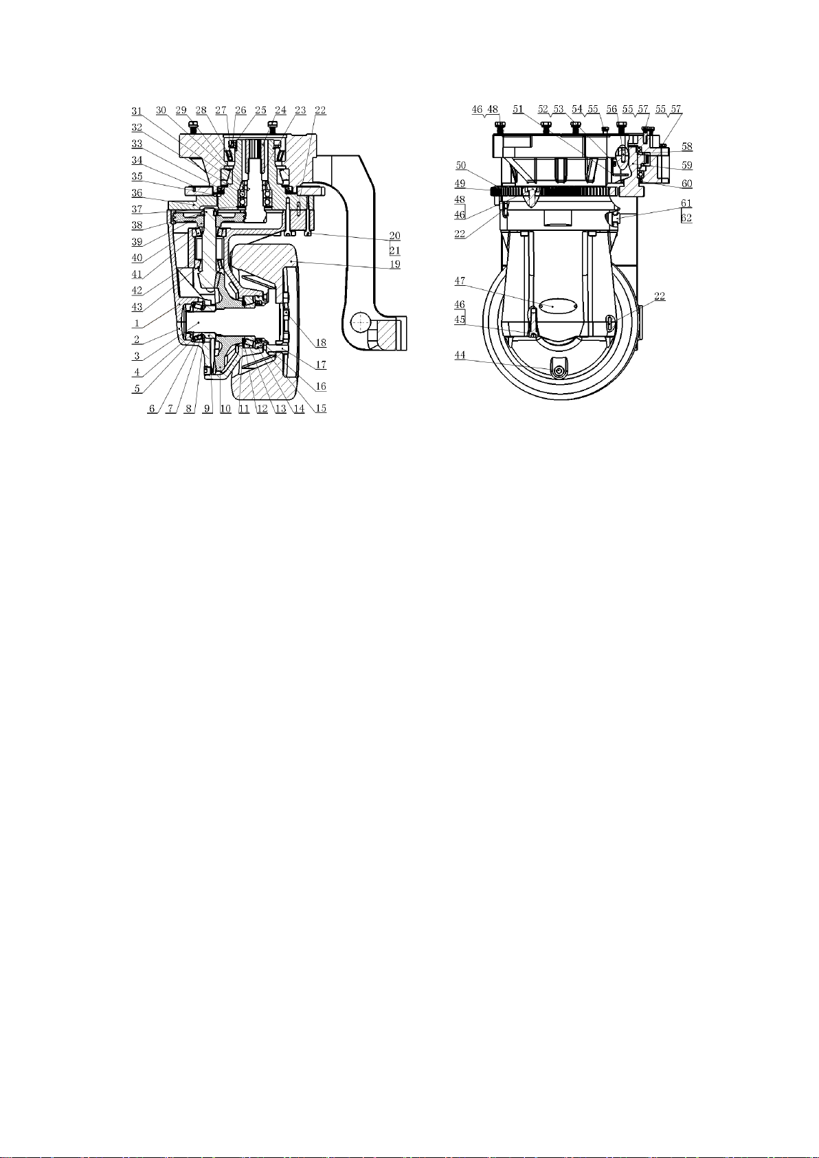
The drive unit of the truck is compact and reasonable arranged. Please see table 1
for its main performance parameters and figure 4-1-1 for structure. The working
principle is that the output shaft of the motor is connected with drive gear through
spline housing, positioned through spline and fixed through retainer ring. First level
deceleration is achieved through gear mesh transmission of the drive gear and driven
gear and the second level deceleration is achieved through gear mesh transmission of
the input shaft and spiral bevel tooth. The power is transmitted to output shaft after a
90°changing of transmitting direction and thus the drive wheel rotates. The steering
mode of the whole drive unit is of electric steering. That is a meshed gear pair is
driven by steering motor. The steering mode is simple and easy.
Table 1
Item
Parameters
Transmission box type
Stepless
transmission
Speed ratio of forward gear
22.6
Speed ratio of reversing gear
22.6
Drive wheel specification
(diameter×width))
φ330×1 40
Oil type
80W/90GL-5
Oil adding quantity
About 3.6L
Total weight (motor and drive
wheel not included)
178Kg
8
Figure 4-1-1 Drive unit
1. Support of transmission box
case
2. Transmission box case cover
3. Drive axle
4. lock nut
5. oil retainer
6. bearing 30209
7. washer
8. retainer ring
9. spacer
10.spiral bevel gear
11. washer
12. retainer ring
13. bearing 30212
14. O ring
15. oil seal holder
16. oil seal
17. hub bolt
18. hub nut
19. tyre 330×114
20.screw M10×60
21. washer 10
22. pin B6×26
23. retainer ring 28
24. Spline housing
25. lock nut
26. screw M6×14
27. lock ring
28. bearing 32017
29. bearing 32019
30. drive gear shaft
31. nut M33×1.5
32. bearing 6207
33. oil seal
34. screw M4×12
35. breather plug
36. tank cover
37. retainer ring 72
38. input shaft
39. lock nut
40. driven gear
41. bearing 30306
42. washer
43. bearing 33206
44. plug 1/2'
45. screw
46. washer 12
47. transmission box plate
48. bolt M6×12
49.steering gear
50. induction ring
51. proximity switch bracket
52. bolt B8×26
53. washer 6
54. bolt M8×70
55. washer 8
56. pin B8×26
57. Bolt M8×30
58. input assembly
59. input shaft assembly
60. oil seal
61. combined washer 16
62. oil addling plug
4.1.2 Disassembling of steering motor
Remove three M8 screws on the steering motor; remove the steering motor from
the steering gear box, at this time, there is steering drive gear and shaft sleeve on the

9
motor shaft. Loose the M10 screw at the end of motor and remove the washer 10,
retainer ring, drive gear and shaft sleeve successively.
4.1.3 Disassembling of diving motor
Remove the four M12 bolts on the drive motor; remove the drive motor from
the gear box.
4.2 Rear axle
4.2.1 Working principle
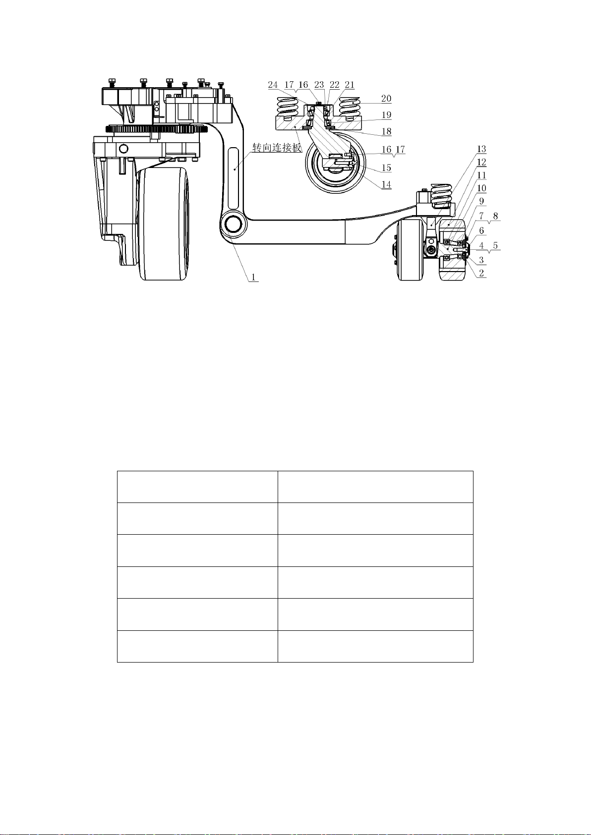
The rear axle is installed on frame through pin at point 1. The rear axle supports
the transmission system and meanwhile, it can reduce the ground pressure of drive
wheel according to the operating surface condition and prevent the drive wheel from
idling.
As a part of rear axle, the balance wheel will rotate with the travelling direction
of truck when steering. The steering knuckle shaft of balance wheel is connected to
the steering connecting plate through two tapered roller bearings. See figure 4-2-1.
When the rear part of the truck is under upwarp condition, install the spring
between steering connecting plate and frame. When the truck is under horizontal
condition, the spring is under compress state. And part of the truck weight is applied
on the steering connecting plate which is transmitted to the balance wheel. Thus the
pressure on the drive wheel is reduced and truck is ensured to contact with ground
with four wheels even on uneven ground.
10
Figure 4-2-1 Rear axle structure
1. bearing
2. adjusting shim
3. block
4. Bolt
5. washer 10
6. guard plate
7. bolt M6x12
8. washer 6
9. bearing 6205-2RS
10. steering shaft
11. bearing 6206-2RS
12. balance wheel
13. steering knuckle
14. steering pin axle
15. lubrication grease fitting
16. bolt M8x16
17. washer 8
18. washer 1
19. bearing 30207
20. spring
21. bearing 30206
22. washer 30
23. nut M30x1.5
24. Steering cover plate
4.3 Steering system
Steering system type
Steering through drive wheel
Steering motor
48V 0.6kw 1350rpm
Deceleration ratio of steering
gear box
1:46
Deceleration ration of gear
transmission
1:5.85
Control type
AC
Steering wheel diameter
φ200mm
The steering system consists of a steering wheel assembly, a electric steering
controller, a steering motor, a steering reduction mechanism and so on. The principle
of the system is below. Angle sensor will send the signal received from the turning of
the hand wheel to steering controller. And then the control voltage which is gotten by

11
the processing of the controller will be put on the two sides of the motor through the
duty ratio of the PWM signal. Through the steering gear deceleration and chain drive
deceleration, the steering wheel will turn a stated angle. The angle degrees with 78°in
forward and 102°in backward will be controlled by the proximity switch on the
steering gearbox. The angle will be feedback and it will be shown on the meter.
4.3.1 Steering wheel assembly
Steering wheel assembly (see fig. 4-3-1) consists of a steering wheel, a steering
bracket, a bearing, a sensor and so on. The function is that it generates a signal of
angle and it doesn’t overcome the force moment of turning, so the turning is easy. The
install position has a 85°degree with the vertical direction. It can not be adjusted
after installment.
Figure 4-3-1 Steering wheel assembly
1. steering wheel
2. steering axle
3. spring
4. Steering bracket assembly
5. bearing 6002-RS
6. elastic coupling
7. steering angle sensor
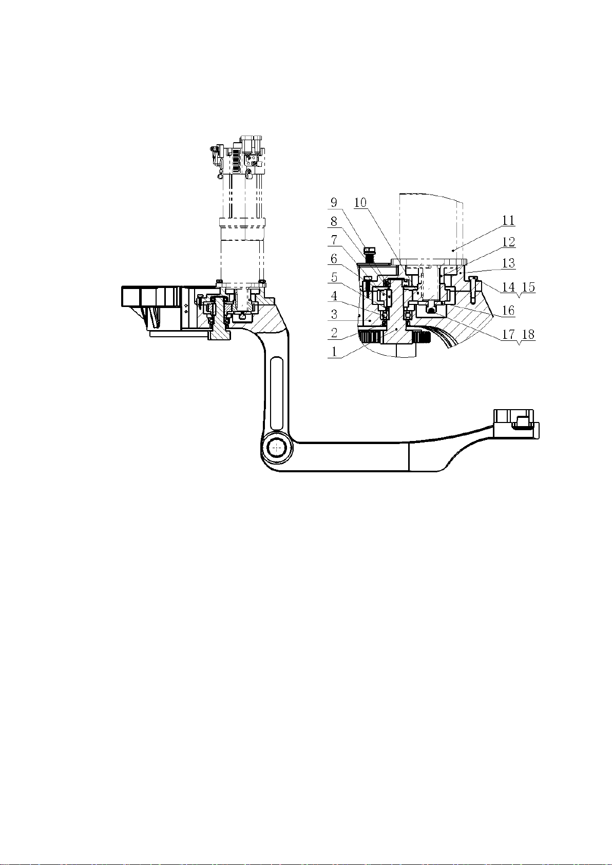
4.3.2 Steering deceleration mechanism
The steering deceleration mechanism (figure 4-3-2) realizes the deceleration of
steering motor. The speed ratio of a pair of meshed gear in the steering gear box is 1:1.
12
The output gear on the output shaft of gear box meshes with steering gear and the
speed ratio is 1:5.85.
Figure 4-3-2 Steering deceleration mechanism
1.output gear
2. oil seal
3. steering connecting plate
4. bearing 6004-2Z
5. shaft sleeve
6. flat key
7. driven gear
8. retainer ring 24
9. bearing 6004-2Z
10. drive gear
11. steering motor
12. shaft sleeve
13. transmission box case cover
14. bolt M8x30
15.washer 8
16. retainer ring
17. screw M10x30
18. washer 10
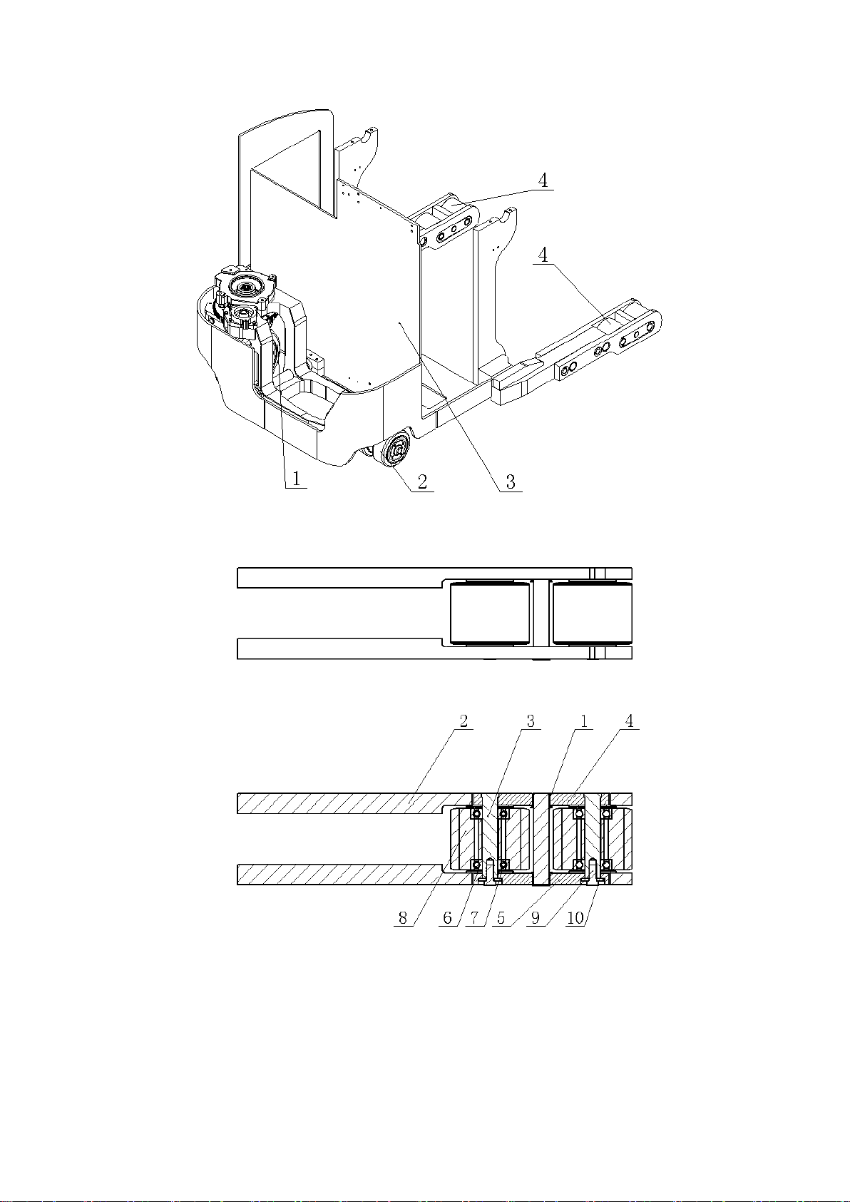
4.4 Supporting wheel assembly
The truck adopts four points supporting structure and the front support is two
symmetrically distributed front load wheel assembly. (See figure 4-4-1).
13
Figure 4-4-1 Diagram of four supporting points
1. Drive wheel 2.Auxiliary wheel 3. Frame 4. Front load wheel assembly
Figure 4-4-2 front load wheel assembly
1. Flange bearing 2. Front leg assembly 3. Pin axle 4. Side plate 1
5. Side plate 2 6. Shim 7. Adjusting shim 8. Load wheel
9. Bolt M12x1.25x25 10. Washer 12
14
The load wheel assembly ( see figure 4-4-2) is mainly made up of 2 bearings,
front leg assembly, pin axle, side plate 1, side plate 2, shims, 2 load wheels, bolt
M12x1.25x25 and washers. Before assembly, apply sufficient grease between 2 load
wheels and change regularly (every 2 month).
4.5 Brake system
4.5.1 Service brake
The truck adopts AC regenerating brake of AC traction motor. There are two
ways to start service brake: one is to release driving operation knob which has weak
brake strength and it is suitable for ordinary condition; the other way is t release brake
pedal which has strong brake strength and it is suitable for emergent condition. (see
figure 4-5-1).
Figure 4-5-1 Service brake
1. Operation knob 2. Brake pedal
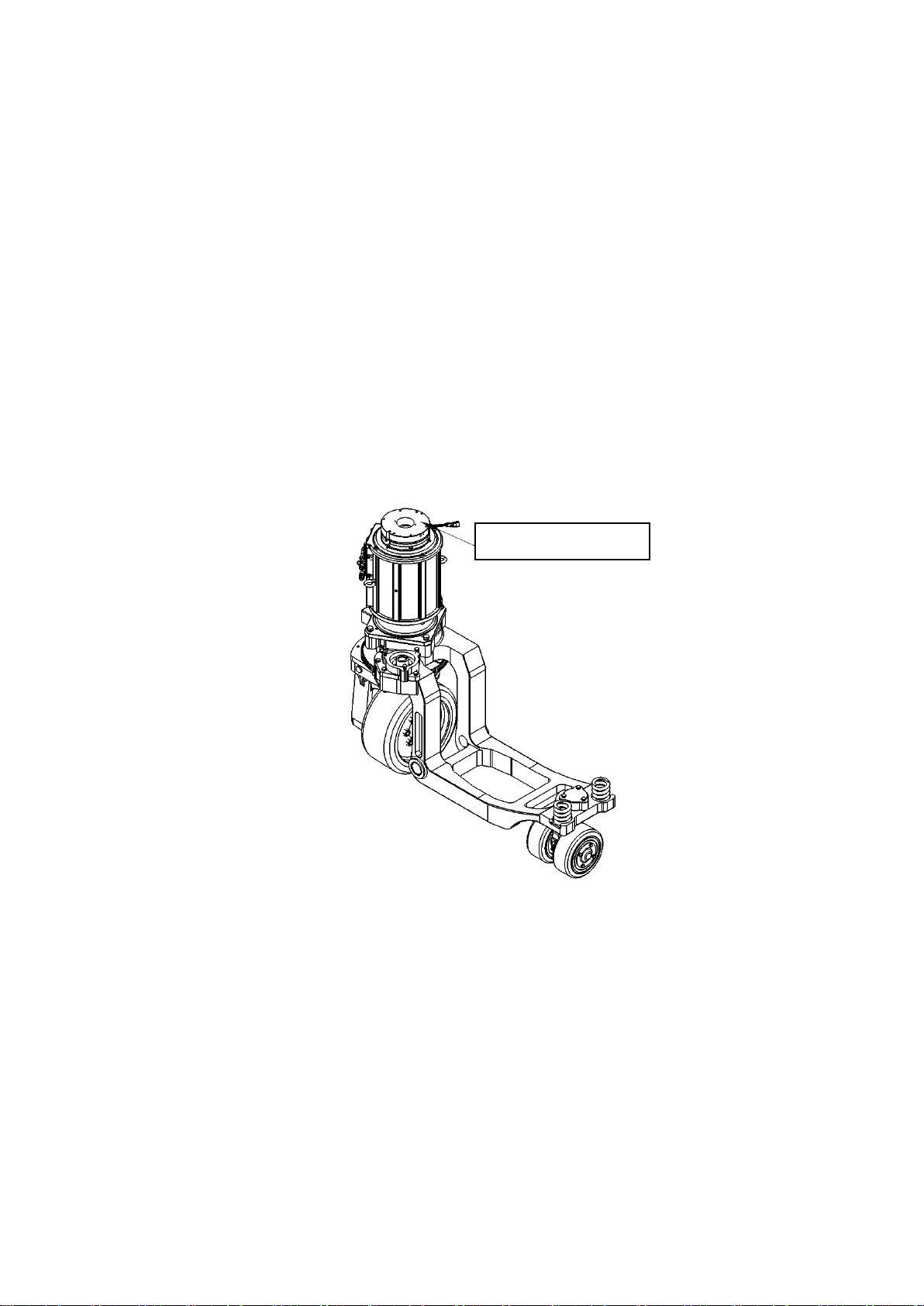
4.5.2 Parking brake
15
Electromagnetic parking brake which is on the top of the shaft end cover of the
AC type traction motor is applied on the truck (see figure 4-5-2). The friction disc is
together with motor shaft. When the key is OFF or the emergency switch is pressed,
the truck has no power, then the electromagnetic parking brake‘s electromagnet has
no power. The armature presses the friction disc tightly, the brake hold the traction
motor shaft tightly and then the motor shaft can not rotate and thus the truck is
parking braked.
When travelling, the electromagnetic parking brake should release the friction
disc. Release the parking brake and the brake condition shown on the LCD is released.
Then the truck can be started.
Figure 4-5-2 Diagram of driving unit
Electromagnetic brake

16
Figure 4-5-3 Installment diagram of electromagnetic parking brake
1. Electromagnetic parking brake 2. Socket head cap screw 3. Elastic washer 8
4. Shim 8 5. Flat key 6. Retainer ring 25
See figure 4-5-2 and figure 4-5-3 for electromagnetic parking brake installment.
(1) Fix the electromagnetic parking brake (item 1) onto the top of the shaft end
cover of the traction motor with 3 socket head cap screws M8x16 (item 2). The
tighten torque of the screw is 25Nm and apply anaerobic adhesive GY-340.
(2) Fix the friction disc built-in spine sleeve of the electromagnetic parking brake
with travelling and traction motor shaft through key 8x25 (item 1). Fix the spine
sleeve upper end with retainer 25 (item 6).
Make sure all parts are firmly installed and be sure they can work smoothly.
Notes when assembling electromagnetic parking brake
Make sure the air gap between the basis of the electromagnet and the amature is
0.3mm. Thus electromagnetic brake can brake reliably when getting electricity and
released reliably when power off.
Please see figure 4-5-4 for electromagnetic brake installment dimensions.
Figure 4-3-8 Rated airgap diagram
This manual suits for next models
2
Table of contents
Other HELI Truck manuals


