Heliocentris Energy Manager 1.3 User manual
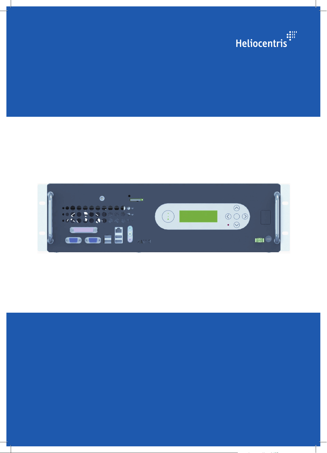
Energy Manager 1.3
Instruction Manual

Energy Manager 1.3, Instruction Manual
Version 1.1
April 2013
© Heliocentris Industry GmbH
Rudower Chaussee 29
12489 Berlin
Germany
All rights reserved. No part of this Instruction Manual may be reproduced, stored in a data
retrieval system or transmitted by any means without the prior written permission of the issuer.
The following exception applies: photocopying pages from the manual for instruction for or by
lecturers is allowed.
Components of the Energy Manager 1.3 are protected by patents and / or utility patents.
Energy Manager 1.3 is a trademark of Heliocentris Industry GmbH, Germany.
We reserve the right to make changes.

Energy Manager 1.3 - Instruction Manual 3
Contents
1About This Document...................................................................... 7
1.1 Overview...................................................................................................7
1.2 Notices and Symbols ..................................................................................8
1.2.1 Symbols ....................................................................................................8
1.2.2 Warnings ..................................................................................................8
1.2.3 Tips ..........................................................................................................8
2Safety Instructions .......................................................................... 9
2.1 General Information on Safety & Responsibility ..............................................9
2.2 Approved Use..........................................................................................10
2.3 Foreseeable Misuse ..................................................................................10
2.4 Hazards during Approved Use ...................................................................10
2.5 General Information on Operation.............................................................11
2.5.1 Requirements for the Owner / Operator......................................................11
2.5.2 Requirements for the Location / Installation Location ....................................11
2.5.3 Requirements for the User .........................................................................12
3Components.................................................................................. 13
3.1 Energy Manager Front Side .......................................................................13
3.2 Energy Manager Rear Side ........................................................................15
3.3 Wiring Board ...........................................................................................15
3.4 Energy Manager Software Modules ............................................................16
3.5 Operating and Monitoring Software ...........................................................17
3.6 Wireless Remote Access ............................................................................18
4Getting Started............................................................................. 19
4.1 Scope of Delivery .....................................................................................19
4.2 Unpacking and Installation ........................................................................19
4.2.1 Unpacking and Visual Inspection................................................................19
4.2.2 Installation Tools ......................................................................................20
4.2.3 How to Mount the Energy Manager ............................................................20
4.3 How to Connect Sensors and Actuators.......................................................21
4.3.1 How to Connect Cables and Plugs .............................................................21
4.3.2 Port Assignment .......................................................................................22
4.4 How to Ground the Energy Manager ..........................................................24
4.5 How to Connect Energy Manager to Power Supply.......................................24
4.6 How to Use the Control Panel....................................................................25
4.6.1 Operating Areas of the Control Panel .........................................................25
4.6.2 How to Select Menu Items .........................................................................27
4.6.3 How to Enter Digits...................................................................................27
4.7How to Login as Service User.....................................................................28
4.8 How to Install the Short Message Service.....................................................29
4.9 How to Configure Site Specific Parameters ..................................................30
4.9.1 How to Connect EM and RMS....................................................................30

Contents
4 Energy Manager 1.3 - Instruction Manual
4.9.2 How to Configure Battery Capacity.............................................................30
4.9.3 How to Configure Fuel Sensors with Fuel Wizard..........................................31
5Operating..................................................................................... 33
5.1 LCD Menu Structure .................................................................................33
5.1.1 Main Menu..............................................................................................33
5.1.2 System Submenu (Sys)...............................................................................35
5.1.3 Genset Submenu (Gen).............................................................................36
5.1.4 Battery Submenu (Batt)..............................................................................39
5.1.5 Fuel Submenu..........................................................................................41
5.1.6 Load Submenu.........................................................................................42
5.1.7 Aircon Submenu.......................................................................................43
5.1.8 Free Cooling Unit Submenu (FCU) .............................................................44
5.1.9 Solar Submenu ........................................................................................45
5.1.10 Wind Submenu ........................................................................................46
5.1.11 Rectifier Submenu (Rect)............................................................................47
5.1.12 Inverter Submenu (Invert)...........................................................................48
5.1.13 Site Submenu...........................................................................................49
5.1.14 Shelter Submenu ......................................................................................50
5.1.15 Login Submenu ........................................................................................51
5.1.16 Service Submenu......................................................................................51
5.1.17 Configuration Submenu ............................................................................52
5.2 How to Administer IP Settings.....................................................................52
5.2.1 How to Display IP Address, Netmask and Gateway Address...........................52
5.2.2 How to Change IP address, Gateway or Netmask ........................................52
5.3 How to Update the EM Software ................................................................53
5.4 How to Reset Counters and Statistics Displays..............................................54
5.5 How to Observe Alarms and Other Events...................................................54
5.6 How to Reset the Service Interval ................................................................56
5.7 How to Copy Log Files to USB Flash Drive...................................................57
6Decommissioning ......................................................................... 58
6.1 How to Decommission the Energy Manager ................................................58
6.1.1 How to Disconnect the Energy Manager......................................................58
6.2 How to Store the Energy Manager ..............................................................59
6.3 How to Ship the Energy Manager ...............................................................59
7Troubleshooting............................................................................ 60
7.1 FAQ .......................................................................................................60
8Maintenance and Service ............................................................. 61
8.1How to Shut Down and Restart Energy Manager ..........................................61
8.1.1 How to Reboot Energy Manager ................................................................61
8.1.2 How to Shut Down Energy Manager ...........................................................62
8.1.3 How to Perform a Forced Restart................................................................63
8.1.4 How to Apply the Reset Button ...................................................................63
8.2 Cleaning .................................................................................................64
8.3 Service ....................................................................................................64
8.4 Replacing Components.............................................................................64

Contents
Energy Manager 1.3 - Instruction Manual 5
8.4.1 How to Replace Main Fuse........................................................................65
8.4.2 How to Replace SIM Card .........................................................................65
8.5 Disposal..................................................................................................65
9Disassembly and Removal............................................................ 66
10 Technical Data.............................................................................. 67


Energy Manager 1.3 - Instruction Manual 7
1About This Document
If only the masculine or feminine form is used in parts of this manual, this
is only used for readability and simplicity. Persons of the respective other
gender are always included.
1.1 Overview
The instruction manual is intended to help you understand, use and
maintain the product. It is structured as follows.
In chapter safety instructions you will find information on the safe handling
of the product. It is essential that you read and understand this chapter.
This chapter presents the components of the product and their basic
functions.
This chapter describes the scope of delivery and the necessary steps for
initial startup of the product - from choosing a suitable installation
location to connecting all required components.
This chapter provides instructions for the operation of the product.
The necessary steps for the disassembly of the product and the conditions
for its packaging, storage and transport are described in this chapter.
This chapter describes possible problems and their solution.
This chapter describes all necessary measures arising in the product life
cycle, such as the maintenance, cleaning, service, warranty and disposal.
An overview of important technical data is provided at the end of the
instruction manual.
The abbreviations used in this manual are summarized in the appendix.
An index can be used for fast orientation.
Safety Instructions
Components
Getting Started
Operating
Decommissioning
Troubleshooting
Maintenance and Service
Technical Data
Abbreviations / Glossary

About This Document
8 Energy Manager 1.3 - Instruction Manual
1.2 Notices and Symbols
1.2.1 Symbols
The following symbols and labels are used in this manual:
Symbol or label
Meaning
Instruction
Aids or prerequisites that are required prior to an action
1.
Instructions in a specific sequence
Result of an action
, -
List
Swit ch, key, b ut ton
Refers to a switch, key, button or icon
Reference to page x
Reference to further information
Figure 1-1 Symbols in the instruction manual
1.2.2 Warnings
The following warnings are used:
DANGER
Warns of dangers of fatal injury.
WARNING
Warns of dangers of serious injury.
CAUTION
Warns of dangers of injury.
NOTICE
Warns of physical damage to the product.
1.2.3 Tips
Useful tips are identified as follows:
TIP
Provides further tips.
Energy Manager 1.3 - Instruction Manual 9
2Safety Instructions
In this chapter you will find information on the safe handling of the
product. It is essential that you read and understand this chapter.
2.1 General Information on Safety & Responsibility
WARNING
Danger of injury due to improper use!
Improper use of the product can result in serious injuries.
Ensure that the manual is accessible at all times.
Make sure you have read and understood this
manual in its entirety.
Comply with all safety instructions and
warnings.
Store the manual and other documentation in a
safe place and pass them on to future owners of the product.
Comply with all local regulations.
Only use product components.
DANGER
Danger of death due to unauthorized modifications!
Conversions and modifications to the product can result in general
hazards (, danger of death due to electric shock).
Do not make modifications to the product or its individual
components.
Do not remove components (exception: See Replacing
Components on page 64).
Its not allowed to replace parts and components which are not
described in this manual. Violation voids all warranty claims.
DANGER
Danger of death due to handling electricity
For electrical wiring follow the country-specific safety
regulations for handling electricity.
For electrical installation comply with the local safety
regulations for handling electricity.
All devices must be connected separately with the earth circuit
connector and properly grounded.

Safety Instructions
10 Energy Manager 1.3 - Instruction Manual
2.2 Approved Use
The product has been designed for:
Monitoring and controlling the power generation
Reducing energy consumption and CO2emission
Remote monitoring of site conditions such as temperature, current,
fuel consumption.
The product is not intended for any other purpose; any other use is not
approved.
2.3 Foreseeable Misuse
Do not use this product for:
Operation beyond the technical specifications
Operation beyond the approved operating environment
Operation in potentially explosive areas
2.4 Hazards during Approved Use
The unit poses no special electrical hazards as long as the following
instructions are observed:
Use only the specified supply voltage, see Technical Data on page
67.
Do not short-circuit inputs and outputs.
Do not reverse the polarity of inputs and outputs.
Do not insert any mechanical parts, especially metal parts, into the
product through the ventilation slots.
Do not use liquids near the product.
Electricity

Safety Instructions
Energy Manager 1.3 - Instruction Manual 11
2.5 General Information on Operation
2.5.1 Requirements for the Owner / Operator
The owner / operator are responsible for the following:
Implementation of a risk analysis in accordance with national law
and regulations concerning occupational health and safety.
The owner / operator are responsible for compliance with local
safety regulations.
The owner / operator must ensure that the unit is accessible only
to the persons defined in this manual.
Unauthorized persons must be prevented, using corresponding
measures, from installing, operating or maintaining the system.
Installation, commissioning, shutdown and maintenance of the
system must be carried out by appropriately qualified personnel.
Only original or replacement parts and maintenance materials
approved by Heliocentris may be used. Violation voids the
warranty.
Heliocentris is not responsible for damage arising from the use of
unauthorized replacement parts and maintenance materials.
It is not allowed to replace parts and components which are not
described in this instruction manual. Violation voids all warranty
claims. the guarantee and all other requirements are lost.
The safety instructions and warnings listed in this instruction
manual must be observed.
2.5.2 Requirements for the Location / Installation Location
Before installation, the installation site is inspected by Heliocentris or an
authorized partner. The requirements for the location are included in the
inspection and are recorded, among other things, in the Site Survey.
The system must be operated in a telecommunication site that
complies with the local regulations.
The Energy Manager is designed for indoor installation in frost-
free premises with a maximum ambient temperature of 50°C in a
noncondensing environment.
The Energy Manager has to be protected against external
influences and kept in a preferably dust-free environment.
TIP
The Energy Manager is not sensitive to normal temperature and
humidity fluctuations that may occur in a telecommunication site.

Safety Instructions
12 Energy Manager 1.3 - Instruction Manual
2.5.3 Requirements for the User
The product for use by trained qualified personnel. Its design does not
correspond to that of a "consumer-oriented" product whose proper use is
generally known and which is protected against operating errors or
improper use.
Installation, service and maintenance may only be done by personnel
authorized and trained by Heliocentris:
Heliocentris staff
Authorized partners
Personnel must be familiar with and comply with the local
applicable accident prevention and safety regulations.
Necessary skills for installation:
Advanced knowledge in electrical engineering
Advanced knowledge in mechanical engineering
Advanced knowledge in reading and developing electrical wiring
diagrams
Additional skills for configuration, service and maintenance:
Good PC knowledge
Basic knowledge in Windows network connection setting
Basic knowledge in Firefox settings
Only Qualified Users
Energy Manager 1.3 - Instruction Manual 13
3Components
The Energy Manager records all essential environmental conditions and
controls, regulates, and monitors the components of the power generation
system in a telecommunication site such as diesel generator, battery, fuel
tank, and air condition.
The modular structure of the Energy Manager allows an implementation
according to customer's demands.
The hardware and software components of the Energy Manager are
briefly explained in the following:
Energy Manager
Wiring board
Energy Manager software modules
Operating and monitoring software
Wireless remote access
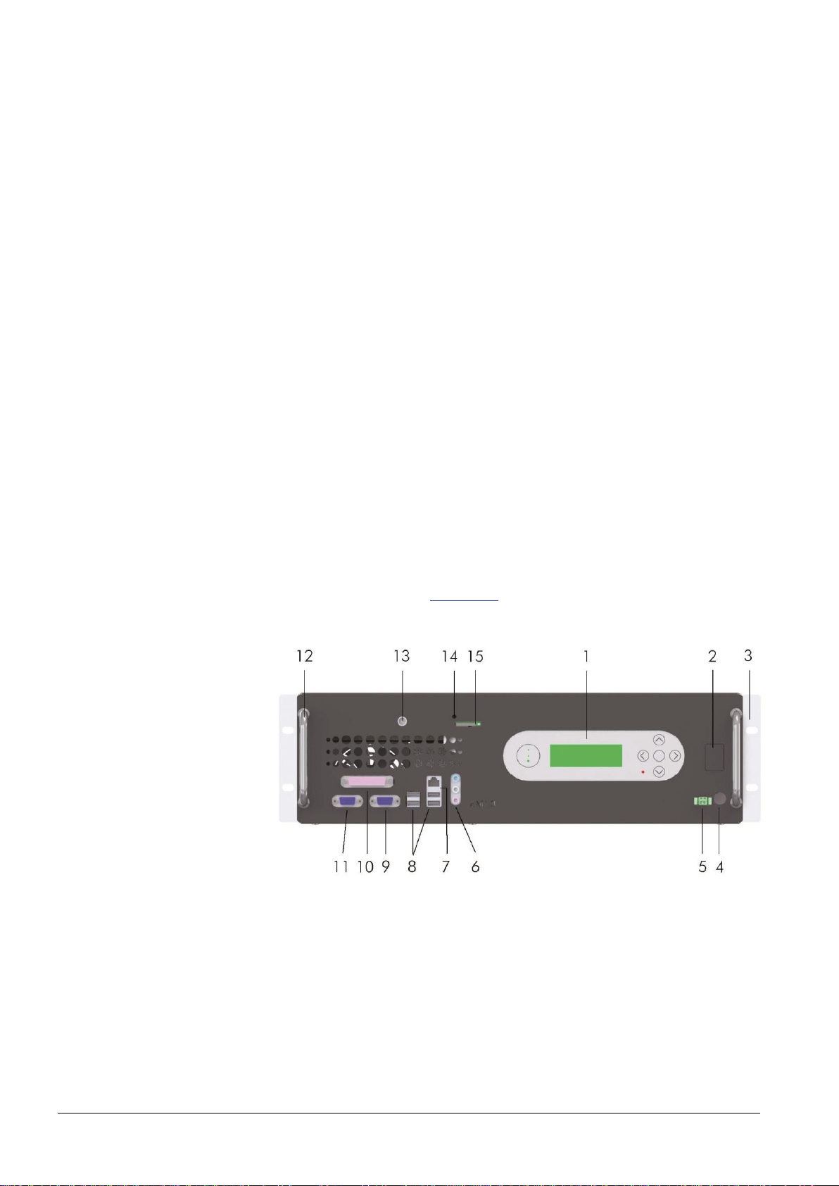
3.1 Energy Manager Front Side
The elements shown in Figure 3-1 are located on the Energy Manager
front side:
Figure 3-1 Energy Manager front side
1Control panel
2Battery power reserve
3Fastening plate
4Main fuse
5Power supply port
6Audio output, empty
7RJ-45 LAN port
84 USB 2.0 ports
9VGA port
10Parallel port, empty
11RS232 port
12Handle
13Antenna port
14 LED
15SIM card holder
Components
14 Energy Manager 1.3 - Instruction Manual
Control Panel
The control panel is the user interface of the Energy Manager. See
Operating Areas of the Control Panel on page 25.
Battery Power Reserve
Switch for internal UPS (optional)
Main Fuse
Fuse to safeguard the power supply
Power Supply Port
Port for the power supply of the Energy Manager
LAN Port
Port for RJ-45 LAN and Ethernet
USB 2.0 Port
4 USB flash drive ports
VGA Port
Analog interface to connect computer and monitor with a 15-pin plug
RS232 Port
Standard serial interface
Antenna Port
Port for antenna of the GPRS modem
SIM Card Holder
Holder to insert SIM card
LED
Light emitting diode showing mode and status of the GPRS modem listed
in Table 3-1:
LED mode
Operating status
Permanently on
Connected to remote party or exchange of
parameters while setting up or disconnecting a
call.
600 ms on / 600 ms off
No SIM card inserted or network search in
progress.
75 ms on / 3 s off
The modem is logged to the network. No data
transfer.
500 ms on / off
Packet switched data transfer in progress. LED
goes on within 1 second after data packets were
exchanged.
Permanently off
No power supply
Table 3-1 LED modes of GPRS modem
Components
Energy Manager 1.3 - Instruction Manual 15
3.2 Energy Manager Rear Side
The elements shown in Figure 3-2 are located on the rear side of the
Energy Manager.
Figure 3-2 Energy Manager rear side
1Fan
2Plug connector for wiring board
3Slot for internal UPS (optional)
4Grounding connection point
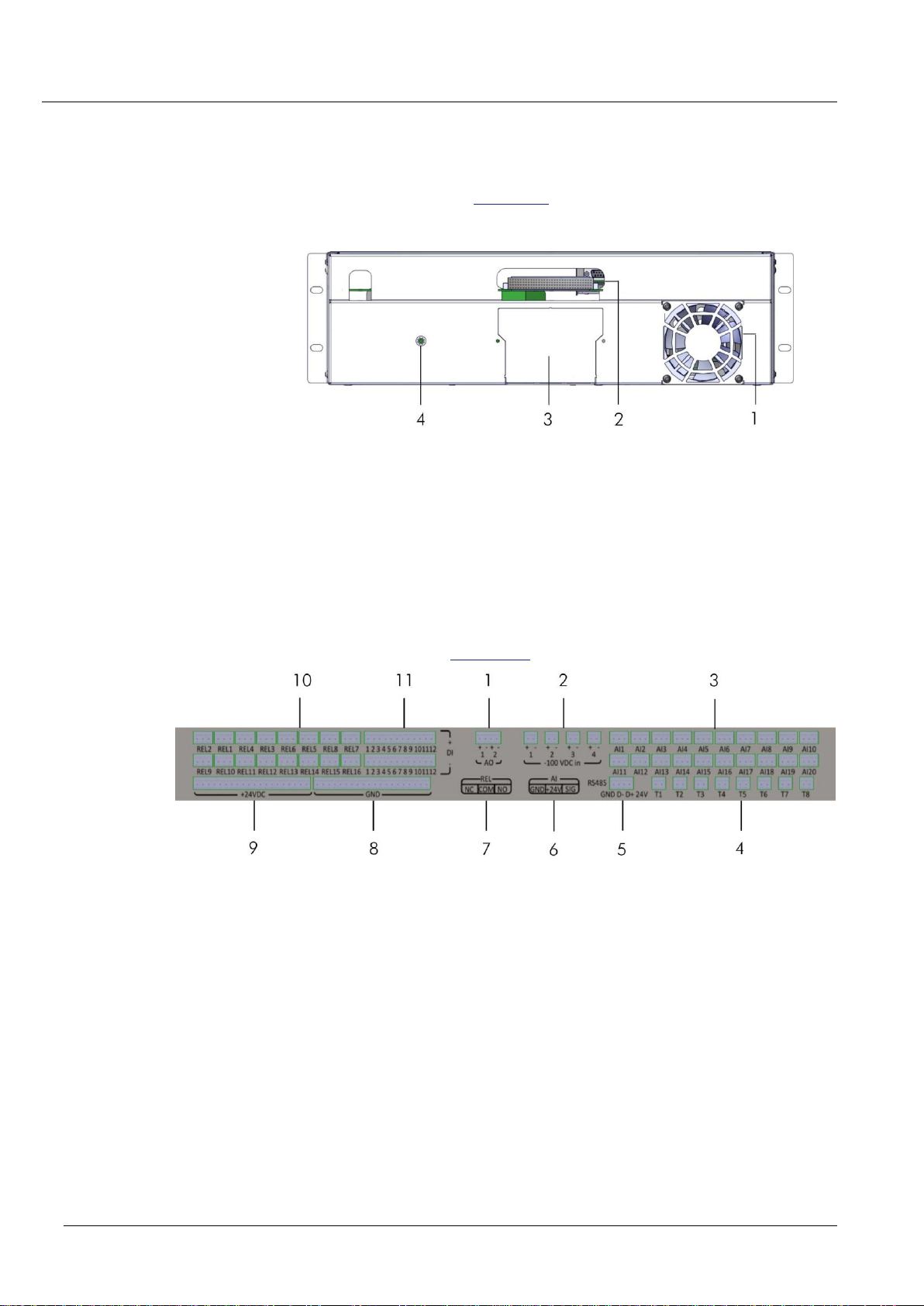
3.3 Wiring Board
The wiring board serves as port expansion. The wiring board is attached
to the rear side of the Energy Manager with a 128-pin plug connector. It
provides ports for analog or digital inputs and outputs. All connecting
points are shown in Figure 3-3.
Figure 3-3 Wiring board ports
1Analog output (2x)
2Analog input large battery (4x)
3Universal input (20x)
4Input for temperature. sensor (8x)
5Serial comm. genset controller
6PIN assignment for analog input
7PIN assignment for relay
8Grounding
9+24 VDC
10 Relay (16x)
11Digital input (12x)

Components
16 Energy Manager 1.3 - Instruction Manual
3.4 Energy Manager Software Modules
The Energy Manager comprises various modules which adapt to the
customer’s needs. The modules are related to specific hardware
components and implemented into the Energy Manager when agreed with
the customer.
In this chapter an overview of the following modules is given. This
overview may not correspond completely to every customized solution.
Genset Management Module
The genset management module controls the diesel generator.
Depending on the system status, the generator is switched on or off. In
order to increase genset efficiency, maintenance, and reliability, the
runtime can be split between different generators and up to 2 genset
management modules can be implemented.
Several generator state variables are monitored: the starter battery voltage
and variables depending on the generator controller hardware like the
coolant level, coolant temperature, and oil pressure. Optionally, a
generator oil management system can be installed and controlled.
Fuel Management Module
The diesel fuel management module monitors data related to the fuel tank
like the measured tank level and related variables such as fuel loss, fuel
refill, total consumption.
Battery Management Module
The battery management module controls the charging and discharging
of the connected batteries. It monitors battery state variables like voltage
and current of the whole battery string, symmetry voltage, state of charge,
state of health, depth of discharge, capacity, battery temperature. Up to
12 banks, each with up to 6 strings can be implemented.
Aircon Management Module
The aircon management module controls the connected air conditioners.
The air conditioners are switched on and off depending on the measured
temperature and selected control algorithm. Different aircon units can be
cascaded in order to start one air conditioner after the other depending
on the required cooling capacity. The runtime of the air conditioners is
logged.
Site Management Module
The site management module monitors general state variables affecting
the whole site, like grid, ambient temperature, humidity, and delivers
alarms like gate, fence, and shelter alarms.
Load Management Module
The load management measures the voltage and calculates the power.
The total energy consumption is calculated in kWh.

Components
Energy Manager 1.3 - Instruction Manual 17
Shelter Management Module
The shelter management module monitors shelter specific state variables
like temperature, humidity, and delivers alarms, like door, motion, smoke,
flood, fence, and seismic alarms.
Free Cooling Unit Module
The free cooling module controls the free cooling unit which is used to
cool a shelter with ambient air. Indoor and outdoor temperature levels are
constantly compared.
Inverter Module
The inverter module measures voltage and current and calculates the
power output and total energy output of up to 6 inverter units installed on
a site.
Rectifier Module
The rectifier module monitors and controls the rectifier. The current limit of
output voltage and battery charge can be set via SNMP.
3.5 Operating and Monitoring Software
For operating and monitoring the Energy Manager comprises the
following software:
System software for entries via the control panel of the Energy
Manager and monitoring of Energy Manager conditions.
Live Access Application (LAA)
The LAA is a Java-based application and runs as a browser
applet. It allows access to the Energy Manager via LAN or GPRS
and remote access via RMS. Administration and configuration
data is entered via LAA.
Remote Management Server (RMS)
The RMS offers 2 web applications: RMS Operation and RMS
Administration. RMS Operating can be used to access the server
and visualize the data acquired by all Energy Managers
implemented in the network. RMS Administration can be used to
access the server and administer customers, regions, users,
sites,hardware and software modules.

Components
18 Energy Manager 1.3 - Instruction Manual
3.6 Wireless Remote Access
Wireless remote access is realized by an internal GRPS / GSM access
modem that is permanently connected to the Internet.
The wireless remote access module is used for:
Connecting the Energy Manager to the Remote Management
Server. Life signals containing site data are sent at regular
intervals from the Energy Manager to a Remote Management
Server and stored there.
Sending event triggered life signals in real time.
Sending events such as diesel fill level, and changes in the status
of the components as SMS message from the Energy Manager to
an administrated telephone number.
Each customer and partner is given a separate login and password that
allow him to have remote access to the Energy Manager on sites and
systems he has been authorized for.
During the transmission of an SMS, the remote access is interrupted. After
the successful transmission of an SMS, a new connection to the server is
automatically created by the wireless access module.
Many kinds of SIM cards from different providers can be used for calling
party address and charging the data transfer.
The SIM card is worldwide Internet-capable through APN
TIP
Heliocentris recommends a data flat rate or a volume rate with a very high
minimum volume. Prepaid cards should not be used.

Getting Started
Energy Manager 1.3 - Instruction Manual 19
4Getting Started
4.1 Scope of Delivery
The following components are delivered by Heliocentris:
Energy Manager
Wiring board
Grounding cable (2 m)
Connecting cable (2 m) from Energy Manager
to –48 VDC distribution
Set of connectors
Sensors (optional)
TIP
On customer request Heliocentris takes responsibility for the delivery and
installation of all hardware and software components for power generation in
the telecommunication site.
4.2 Unpacking and Installation
To install the Energy Manager the following steps are necessary:
Unpacking and Visual InspectionInstallation in a 19-inch rack
Connecting sensor cables to wiring board
Grounding
Connecting the power supply
Inserting SIM card
TIP
A connection to an external power supply grid is realized exclusively by
the customer or a qualified company.
4.2.1 Unpacking and Visual Inspection
A delivery receipt is delivered with the device.
Check for the correct number as per delivery receipt.
Check all parts for external damage.

Getting Started
20 Energy Manager 1.3 - Instruction Manual
4.2.2 Installation Tools
For a standard installation the following tools are needed:
Standard tool box including:
Hex keys
Set of wrenches (metric)
Flathead screw driver set
Grippers
Wire cutter
Crimping tool
1 - 6 mm² duct tape
Digital multimeter
Clamp-on ammeter DC
4.2.3 How to Mount the Energy Manager
The Energy Manager is integrated in a free unit of a 19-inch-rack and
requires 3 height units.
The rack is fastened with wall or floor fasteners to prevent it from
tilting over.
Install the Energy Manager as follows:
1. Take Energy Manager with both hands from the front side and insert it
into the rack.
If there is enough space for wiring from behind the backside of the Energy
Manager:
Fasten the device with2 screws on the left and on the right side.
If there is not enough space for wiring from behind the backside of the
Energy Manager:
Proceed with wiring the device (see How to Connect Sensors on
page 21). Only after wiring fasten the device as described above.
Table of contents
Other Heliocentris Power Supply manuals


