Helios Power Solutions BRAVO ST 230 VAC User manual

Important Safety Instructions
Save these Instructions
DUAL INPUT INVERTER
The Commercial Power as default source
AC BACKUP IN A DC ENVIRONMENT
Leverage your existing DC infrastructure
ONE STOP SHOP
Wide output power range
HARSHEST AC INPUT CONDITIONS
Without compromising the quality of the AC output
BEYOND THE INVERTER
THE NEW GENERATION OF POWER CONVERTERS
www.heliosps.com
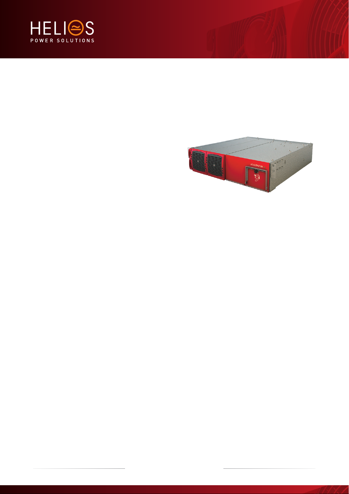
BRAVO ST - 230 VAC
User Manual V7.3

2 – Bravo ST 230 VAC– User manual – v7.3
Table of content
1. CE+T at a glance ...................................................................................................................................................... 5
2. Abbreviations ........................................................................................................................................................... 6
3. Warranty and Safety Conditions ................................................................................................................................ 7
3.1 Handling........................................................................................................................................................... 8
3.2 Surge and transients ........................................................................................................................................ 8
3.3 Other................................................................................................................................................................ 8
4. TSI TECHNOLOGY ..................................................................................................................................................... 9
4.1 On-line Mode.................................................................................................................................................... 10
4.2 Safe mode........................................................................................................................................................ 10
4.3 EPC-mode ........................................................................................................................................................ 10
4.4 Mix Mode & Walk-in-mode ............................................................................................................................... 10
4.5 By Pass Mode................................................................................................................................................... 11
5. Description ............................................................................................................................................................... 12
5.1 Typical load ...................................................................................................................................................... 13
6. Bravo ST Components............................................................................................................................................... 14
6.1 Inverter Module ................................................................................................................................................ 14
6.2 Automatic By-Pass Module............................................................................................................................... 14
6.3 Sub-rack .......................................................................................................................................................... 15
7. Accessories .............................................................................................................................................................. 16
7.1 T2S-2C Interface .............................................................................................................................................. 16
7.1.1 Parameters setting................................................................................................................................ 16
7.1.2 System diagnostic and troubleshooting ................................................................................................ 16
7.1.3 On-the-fly monitoring ........................................................................................................................... 16
7.2 Surge Arresters................................................................................................................................................. 16
8. Bravo ST Shelves Installation .................................................................................................................................... 17
8.1 Unpacking the system ...................................................................................................................................... 17
8.2 Mechanical Installation ..................................................................................................................................... 17
8.2.1 System Dimensions .............................................................................................................................. 17
8.2.2 Fixing.................................................................................................................................................... 17
8.2.3 Mounting Kit ......................................................................................................................................... 18
8.3 Electrical installation......................................................................................................................................... 19
8.3.1 Pre requisites........................................................................................................................................ 19
8.3.2 Terminations......................................................................................................................................... 20
8.3.3 Grounding............................................................................................................................................. 20
8.3.4 DC Input ............................................................................................................................................... 21
8.3.5 AC Input (AC Input protection mandatory).............................................................................................. 21
8.3.6 AC output.............................................................................................................................................. 21
8.3.7 Signalling.............................................................................................................................................. 21
8.3.8 Rear cover ............................................................................................................................................ 23
9. Human-Machine Interface......................................................................................................................................... 24
9.1 Inverter module (Requires firmware V203 or higher) ......................................................................................... 24

3 – Bravo ST 230 VAC– User manual – v7.3
9.2 T2S .................................................................................................................................................................. 25
10. System set up........................................................................................................................................................... 26
10.1 Communication Setting .................................................................................................................................... 26
10.2 Menu access .................................................................................................................................................... 27
11. Inserting/removing/replacing modules ...................................................................................................................... 28
11.1 TSI Inverter....................................................................................................................................................... 28
11.1.1 Module Removal................................................................................................................................... 29
11.1.2 Inserting ............................................................................................................................................... 29
11.2 TSI By-Pass Module Replacement..................................................................................................................... 30
11.2.1 Removal ............................................................................................................................................... 30
11.2.2 Inserting ............................................................................................................................................... 30
11.3 T2S .................................................................................................................................................................. 31
11.3.1 Removal ............................................................................................................................................... 31
11.3.2 Inserting ............................................................................................................................................... 31
11.4 Fan replacement............................................................................................................................................... 31
12. Commissioning ........................................................................................................................................................ 33
12.1 Check list ......................................................................................................................................................... 34
13. Trouble Shooting and Defective Situations Fixing....................................................................................................... 35
13.1 Trouble Shooting............................................................................................................................................... 35
13.2 Defective modules............................................................................................................................................ 36
13.2.1 Replacing modules ............................................................................................................................... 36
13.2.2 Return defective T2S interface ............................................................................................................. 36
13.2.3 Return defective shelf .......................................................................................................................... 36
13.2.4 Return defective modules ..................................................................................................................... 36
14. Service .................................................................................................................................................................... 37
15. Maintenance Task..................................................................................................................................................... 38
Release Note:
Version Release date
(DD/MM/YYYY)
Modified page
number Modifications
7.0 18/12/2014 - First release of the Manual.
7.1 08/04/2015 - Amendment and correction
7.2 27/02/2018 11, 13, & 15 Updated the information
7.3 13/04/2018 25 Updated Parameters
4 – Bravo ST 230 VAC– User manual – v7.3

1. CE+T at a glance
CE+T Power designs, manufactures and markets a range of products for industrial operators with mission critical applications,
who are not satisfied with existing AC backup systems performances, and related maintenance costs.
Our product is an innovative AC backup solution that unlike most used UPS’s
Maximizes the operator’s applications uptime;
Operates with lowest OPEX;
Provides best protection to disturbances;
Optimizes footprint.
Our systems are:
Modular
Truly redundant
Highly efficient
Maintenance free
Battery friendly
CE+T puts 60+ years expertise in power conversion together with worldwide presence to provide customized solutions and
extended service 24/7 - 365
5 – Bravo ST 230 VAC– User manual – v7.3
CE+T at a glance

2. Abbreviations
TSI Twin Sine Innovation
EPC Enhanced Power Conversion
REG Regular
DSP Digital Signal Processor
AC Alternating current
DC Direct current
ESD Electro Static Discharge
MET Main Earth Terminal
MBP Manual By-pass
TCP/IP Transmission Control Protocol/Internet Protocol
USB Universal Serial Bus
PE Protective Earth (also called Main Protective Conductor)
N Neutral
PCB Printed Circuit Board
TRS True Redundant Structure
MCB Miniature Circuit Breaker
MCCB Molded Case Circuit Breaker
CB Circuit Breaker
6 – Bravo ST 230 VAC– User manual – v7.3
Abbreviations

3. Warranty and Safety Conditions*
WARNING:
The electronics in the power supply system are designed for indoor, clean environment.
When installed in dusty and/or corrosive environment, outdoor or indoor, it is important to :
Install an appropriate filter on the enclosure door, or on the room’s air control system
Keep the enclosure door closed during operation
Replace the filters on a regular basis.
Important Safety Instructions and Save these Instructions.
The inverter system/rack can reach hazardous leakage currents. Earthing must be carried out prior energizing the system.
Earthing shall be made according to local regulations.
Prior to any work conducted to a system/unit make sure that AC input voltage and DC input voltage is disconnected.
CAUTION – Risk of electric shock. Capacitors store hazardous energy. Do not remove cover until 5 minutes after
disconnecting all sources of supply.
CAUTION – Risk of electric shock. This Inverter / UPS receives power from more than one source. Disconnection of the AC
source and DC source is required to de-energize this unit before servicing.
Maximum operating ambient temperature is 40º C (104º F).
AC and DC circuits shall be terminated with no voltage / power applied.
Some components and terminals carry high voltage during operation. Contact may result in fatal injury.
Warning labels must not be removed.
Never wear metallic objects such as rings, watches, bracelets during installation, service and maintenance of the product.
Insulated tools must be used at all times when working with live systems.
When handling the system/units pay attention to sharp edges.
ESD Strap must be worn when handling PCBs and open units.
The inverter system/rack is not supplied with internal disconnect devises on input nor output.
The inverter rack is a dual input power supply. The complete system shall be wired in a way that both input and output
leads can be made powerless in a single action.
REG systems can be seen as independent power sources. To comply with local and international safety standards N (output)
and PE shall be bonded.
EPC system that have no AC input wired and connected to comply with local and international safety standards N (output)
and PE shall be bonded. The bonded between N output and L must be removed once the AC input is being connected.
The safety standard IEC/EN62040-1-1 requires that, in case of output short circuit, the inverter must disconnect in maximum
5 seconds. However, if the parameter is set at a value > 5 seconds, an external protection must be provided in order that the
short circuit protection operates within 5 seconds. Default setting is 60s.
The equipment must be installed and commissioned by skilled technicians according to instructions in this manual.
* These instructions are valid for most CE+T Products/Systems. Some points might however not be valid for the product
described in this manual
7 – Bravo ST 230 VAC– User manual – v7.3
Warranty and Safety Conditions

Local regulations must be adhered.
The manufacturer declines all responsibilities if equipment is not- installed according to -instructions herein -by skilled
technician -according to local safety regulation.
Warranty does not apply if the product is not installed, used and handled according to the instructions in the manuals.
CE+T cannot be held responsible for disposal of the Inverter system and therefore the customer must segregate and
dispose the materials which are potentially harmful to the environment, in accordance with the local regulations in force in
the country of installation.
If the equipment is dismantled, to dispose of the products it consists of, you must stick to the local regulations in force in
the country of destination and in any case avoid causing any kind of pollution.
System is designed for installation in an IP20 or IP21 environment. When installed in a dusty or humid environment,
appropriate measures (air filtering …) must be taken.
3.1 Handling
The cabinet shall not be lifted using lifting eyes.
Remove weight from the cabinet by unplugging the inverters. Mark inverters clearly with shelf and position for correct. This
is especially important in three phase configurations.
Empty inverter positions must not be left open. Replace with module or cover.
3.2 Surge and transients
The mains (AC) supply of the modular inverter system shall be fitted with suitable Lightning surge suppression and Transient
voltage surge suppression for the application at hand. Manufacturer’s recommendations of installation shall be adhered. It is
advisory to select device with alarm relay for function failure.
Indoor sites are considered to have a working lightning surge suppression device in service.
Indoor sitesMin Class II.
Outdoor sites Min Class I + Class II or combined Class I+II.
3.3 Other
Isolation test must not be performed without instructions from the manufacturer.
To download the latest documentation and software, please visit our website at www.cet-power.com.
8 – Bravo ST 230 VAC– User manual – v7.3
Warranty and Safety Conditions

9 – Bravo ST 230 VAC– User manual – v7.3
TSI TECHNOLOGY
4. TSI TECHNOLOGY 1
Inverter modules carrying the TSI logo and the EPC mark are triple port converters (AC in, DC in, AC out). Sinusoidal output is
converted from Mains or/and DC.
The block diagram here below gives an explicit description of the topology and operation.
BOOST
DSP
T2S
EMI
FILTER
EMI
FILTER
EMI
FILTER
User
Interface
Redundant
Commuication
Bus
L
N
L’
N’
-
+
Local Signaling
The module is built around the following sub-converters
AC to DC at input
DC to DC at input
DC to AC at output
The energy can flow either from the AC source or the DC source under the control of the local DSP controller. Thanks to internal
energy buffering, the output sine wave is constant and disturbance free regardless of the active source.
The BOOST functionality multiplies the nominal current for a period of 20ms(max) in the event of down stream current surge. The
upstream breakers do not have to be oversized to prevent tripping. After the boost has been activated or if the AC input is not
present the overload capacity is 150% for 15 seconds regardless of the source currently used.
The TSI works according to True Redundant Structure (TRS) that features decentralized and independent logic, redundant
communication bus and three internal levels of disconnection to isolate a module after internal failure.
The functionality is included in every inverter module. Running them in parallel provides a modular system with, no single point of
failure, always conditioned output, high system efficiency and 0ms source transfer time.
1 | Information and data given in this chapter intend to for an overview on the technology. Detailed features and parameters for each individual module type of the
range may differ and should be referred in the dedicated data sheet.

10 – Bravo ST 230 VAC– User manual – v7.3
TSI TECHNOLOGY
4.1 On-line Mode
DC is the primary source of supply whilst Mains (AC) works as the secondary source of supply. Switching time between DC input
and AC input is 0ms (source transfer).The power delivered by the DC source (usually a battery , but it could be any other type of
DC generator) is converted to provide regulated and transient free power to the load. In case of short circuit at the load side, the
boost is automatically, timely and energized for a specific duration to trip downstream protective devices.
4.2 Safe mode
Safe mode uses DC as primary source of supply while Mains (AC) is in standby.
Mains (AC) is normally disconnected through internal inlet relay and is only connected when down stream clearance is required
(boost) or if DC is unavailable.
The transfer between DC and AC results in typical transfer time of 10ms.
Typically the safe mode is used in extremely harshed environments such as railways. Under such conditions it provides extra
isolation against disturbances carried by the Mains.
4.3 EPC-mode
Mains input (AC) is the primary source whilst DC works as backup.
The TSI is designed to operate on Mains on permanent basis and to deliver output voltage conditioned with low THD.
There is no physical difference on the output sine wave whether the source is AC (or) DC. If the Mains is out of tolerance or goes
down, the converter seamlessly switches to DC and the converter operates in “Back-up mode”
(Switching time back and forth is 0 ms).
As soon as the Mains returns in to valid range, the EPC mode is automatically resumed.
The EPC mode offers higher efficiency (up to 96% depending on the model) without compromising the purity of the output sine
wave.
NOTICE: REG modules:
Inverter modules carrying the TSI logo together with REG mark are modules working only with DC input .
Sinusoidal output is converted from DC and the module operates as a traditional inverter. EPC mode and the
boost are not available with REG modules.
4.4 Mix Mode & Walk-in-mode
Under some circumstances DC and AC source can be combined. The sequence is defined by a user selectable set of parameters,
start, control and exit are fully automatic .
A specific example of Mix-mode is the Walk-in mode where the transfer from DC source to AC source is ramped up within a fix
and adjustable period of time.
Setting for Walk -in -Mode and Mix Mode can be made through the T2S supervisor configuration file. See section10, page 26
for more information on T2S supervisor.

11 – Bravo ST 230 VAC– User manual – v7.3
TSI TECHNOLOGY
4.5 By Pass Mode
The automatic by pass is engaged in case of following condition
AC input is present and 1 BRAVO TSI Module failure if no redundancy configured OR only one module installed
OR
AC input is present and 2 BRAVO TSI module failure if one module redundant has been configured.
The automatic by pass IS NOT AVAILABLE if:
No AC input is present
AC output LOAD exceed 5 kVA
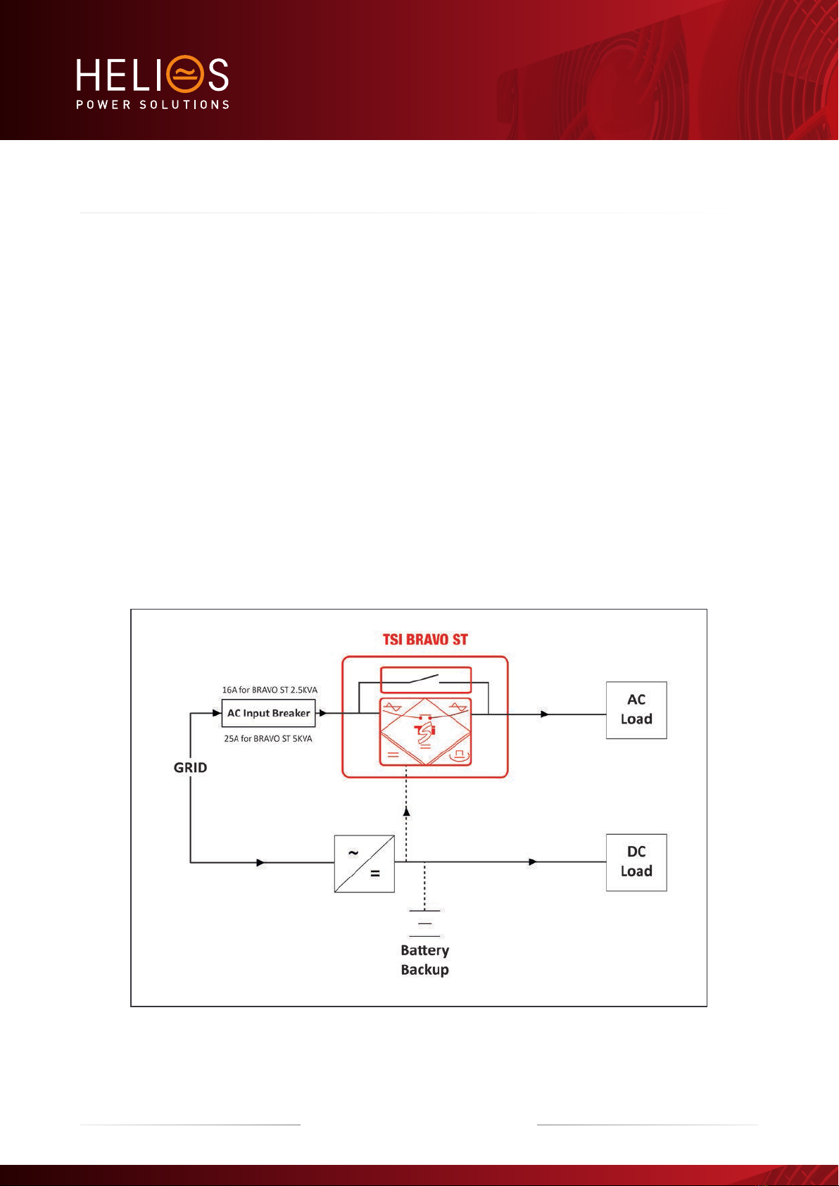
5. Description
Bravo ST has been designed to give quality power, ease of use, and reliability. It provides up to 4000 watts (Bravo ST 5 KVA) or up
to 2000 watts (Bravo ST 2.5 KVA).
In normal operation:
AC input present the TSI module will operate in EPC mode.
AC input fail the TSI module will switch to DC (battery) and continue to feed the load.
DC input fail the system operate on AC input.
TSI module fail (N+1):
If N+1 configuration selected the second module will continue to feed the load.
If the second module fail the system will switch to AC through the automatic by pass to allow module replacement.
TSI module fail (N no redundancy):
If one module fail the BRAVO ST will switch to AC through the automatic by pass to allow module replacement.
All part of the BRAVO ST (Inverter modules and by pass module) are hot swappable without shut down of the AC output.
Warning:
If all modules fails and AC input not present, the system will stop to prevent “backfeed” protection upstream.
12 – Bravo ST 230 VAC– User manual – v7.3
Description
Bravo ST 230 VAC is a standalone Inverter with following capacities.
Standalone model 5000 VA (3000VA in 24VDC).
Standalone model 2500 VA, with Redundancy (1500VA for 24VDC).
Standalone model 2500 VA, without Redundancy (1500VA for 24VDC).
230Vac and 48Vdc as Input and 230Vac as Output fitted with Enhanced Power Conversion (EPC) mode (Other DC input voltage
24VDC, 110VDC, 220VDC will be available).
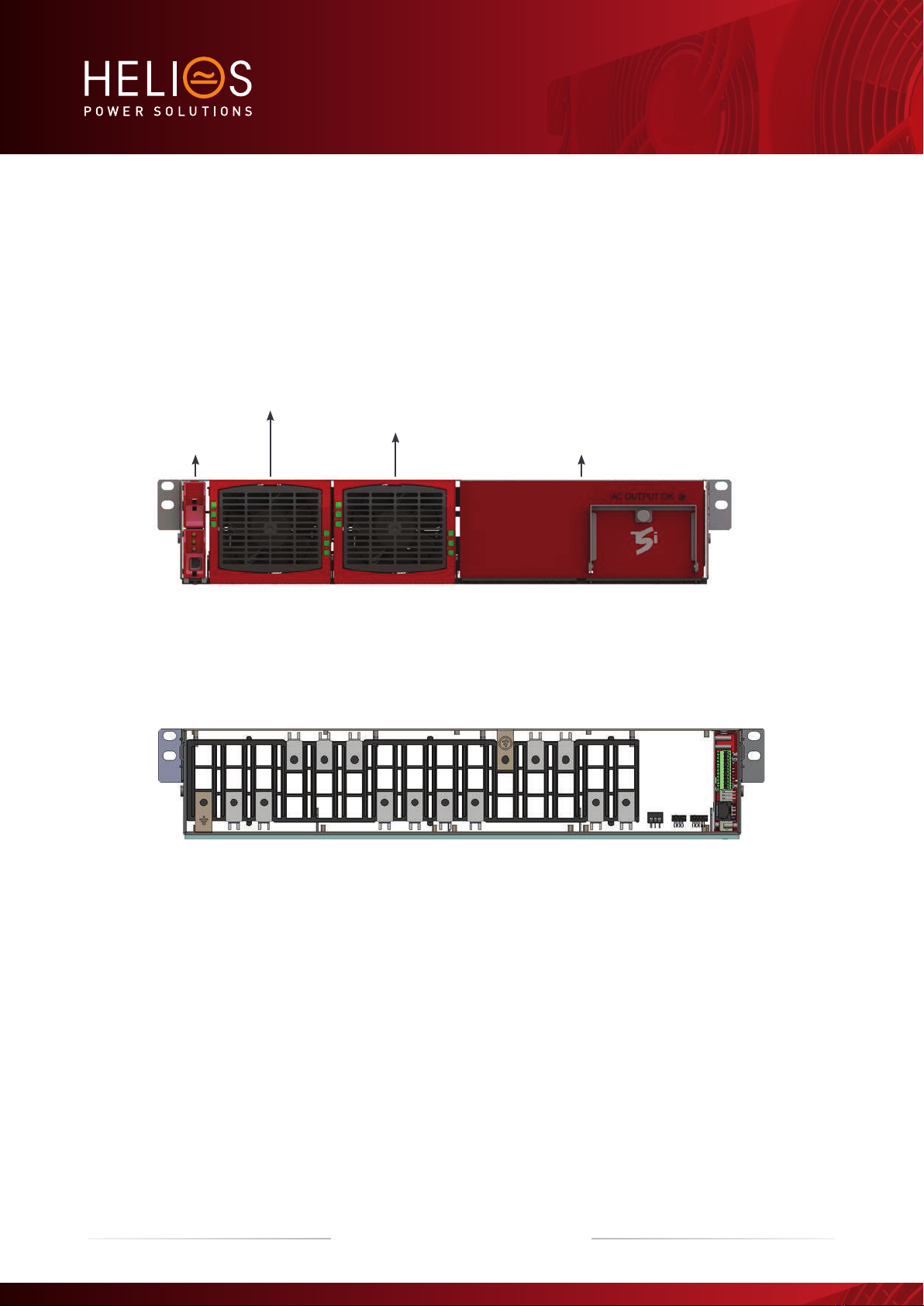
Inverter Module 1
Inverter Module 2
By Pass ModuleT2S USB
Front View
Rear View
5.1 Typical load
Resistive.
Inductive and resistive.
Capacitive and resistive.
13 – Bravo ST 230 VAC– User manual – v7.3
Description
14 – Bravo ST 230 VAC– User manual – v7.3
Bravo ST Components
6. Bravo ST Components
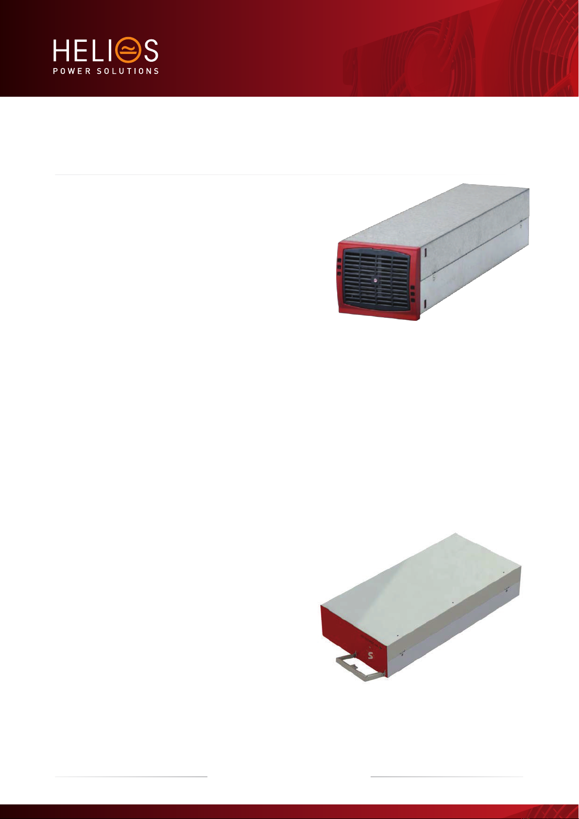
6.1 Inverter Module
Bravo: 24 VDC 1500 VA-230 VAC.
48 VDC 2500 VA-230 VAC.
60 VDC 2500 VA-230 VAC.
110 VDC 2500 VA-230 VAC.
220 VDC 2500 VA-230 VAC.
The BRAVO module shall have software version V203 or higher to operate with BRAVO ST.
The TSI Bravo is a 2500VA/2000W converter based on the TSI technology (see section 4). 1500VA/1200W for 24VDC
The TSI inverter modules are hot swappable and hot pluggable. They are featured with self setting capabilities for easy
plug-and-play operation.
LED’s on module front plate display the status of converter and output power.
Inverter modules can be combined to build any single or multi-phase structures.
The inverter modules are equipped with soft start.
The fan is equipped with alarm and run time meter. It is field replaceable.
17.13” (D) x 4.02” (W) x 3.46” (H). [435mm (D) x 102mm (W) x 88mm (H)].
11 lbs [5 kg].
6.2 Automatic By-Pass Module
5000 VA By-Pass.
Will automatically connect the load to the commercial grid (if
available) when one or both inverter modules are not available.
Transfer time <10ms.
Hot pluggable: can be removed without shutting down the
system provided that sufficient inverter modules are present
and running.
6.3 Sub-rack
The BRAVO ST 230 VAC shelf shall be integrated in min 600mm deep cabinets, 19 Inch / ETSI mounting.
The BRAVO ST 230 VAC shelf houses maximum two (2) inverter modules and one (1) T2S interface. Maximum 5KVA per
shelf.
The Bravo ST 230 VAC shelf is designed with individual DC
input, common AC input and common AC output.
Optional rear cover can be provided for enhanced safety in
cabinet.
18.9” (D) x 19” (W) x 2U (H). [480mm (D) x 19” (W) x 2U (H)].
13 lbs [6 Kg] empty.
15 – Bravo ST 230 VAC– User manual – v7.3
Bravo ST Components

7. Accessories
7.1 T2S-2C Interface
The T2S is an interface giving access to the TSI modules that are connected together in any TSI systems.
The T2S doesn’t perform any control or management of the TSI system. It can be removed, replaced or moved to another live
system without affecting neither the original TSI system operation nor the target system.
7.1.1 Parameters setting
The T2S interface is featured with a USB connector at the front. Connected to a laptop, it enables TSI system settings, modules
and phase assignments, and other various adjustments to allow TSI best fit with actual site conditions.
(Operation of T2S is described in separate manual available on request).
7.1.2 System diagnostic and troubleshooting
The T2S is featured with built-in user interface to allow on-line diagnostic through laptop.
Installers and maintenance technicians should always carry proper laptop to access/reconfigure the system on site.
7.1.3 On-the-fly monitoring
The T2S is featured with
3 outgoing alarms contacts.
2 digital inputs.
MOD bus.
CAN bus (optional).
Alarm monitoring.
Record the latest 200 events. FIFO.
7.2 Surge Arresters
The mains (AC) supply of the modular inverter system shall be fitted with suitable Lightning surge suppression and Transient
voltage surge suppression for the application at hand. Manufacturer’s recommendations of installation shall be adhered. It is
advisory to select a device with an alarm relay for function failure.
Surge arrestor(optional) is installed in the system.
Indoor sites are considered to have a working lightning surge suppression device in service.
Indoor sitesMin Class II.
Outdoor sites Min Class I + Class II or combined Class I+II.
16 – Bravo ST 230 VAC– User manual – v7.3
Accessories

8. Bravo ST Shelves Installation
8.1 Unpacking the system
BRAVO ST is packed in a wooden box.
Modules are packed seperately. They are normally marked to be replaced in the right slot
Module packing material shall be taken apart and stored in case of return under warranty. Unproper packing may void the
warranty.
The packing material of the TSI system is recyclable.
8.2 Mechanical Installation
Sub-rack is preferable mechanically fixated without modules.
T2S-2U can be left in the sub-rack.
Min two (2) fixing screws per side of the sub rack.
Fixing holes for Inch and ETSI mounting frames.
System is designed for installation in an IP20 or IP21 environment. When installed in a dusty or humid environment,
appropriate measures (air filtering …) must be taken.
8.2.1 System Dimensions
8.2.2 Fixing
A full range of accessory is ready made to allow easy integration of the TSI in almost any kind of standard cabinets. Among other
we provide fixing set for:
19” – 600mm depth cabinets (most standard solution, which is supplied by default - shown here).
19” – 800mm depth cabinets.
ETSI – 600mm depth cabinets.
17 – Bravo ST 230 VAC– User manual – v7.3
Bravo ST Shelves Installation
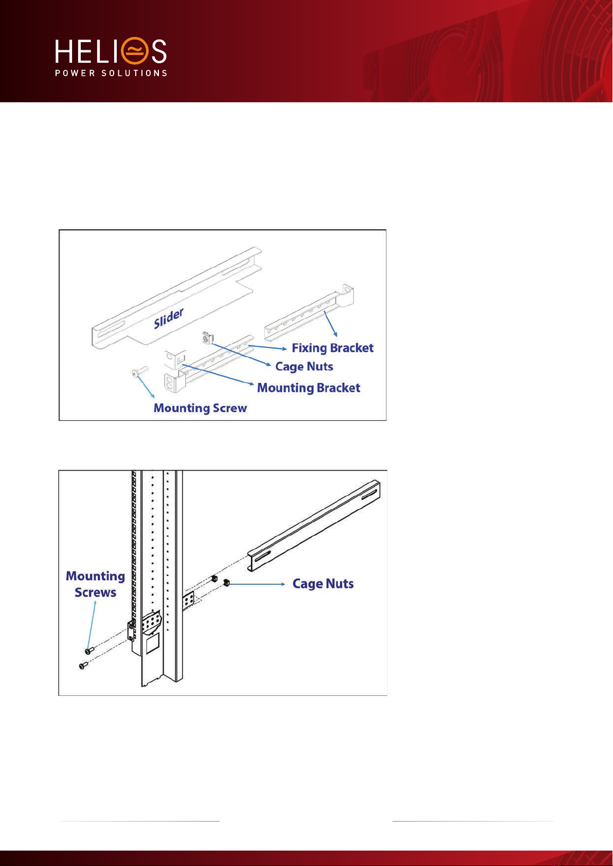
8.2.3 Mounting Kit
Make sure that you have received the proper accessories for Bravo ST 230 VAC which consist of 1 pair of 19” kit as shown
following Figure.
The fixing brackets, together with the sliders, allow for different cabinet depths.
Slider - 2 Nos.
Brackets - 4 Nos.
Latches - 2 Nos.
Bolts - 12 Nos.
Removable nuts - 12 Nos.
Assemble the sliders and adjust
the length to suit the mounting
depth
Fix cage nuts in the cabinet front
and rear frame of the left and the
right side
Fix the left and right slider of the
cabinet with the supplied mounting
screws.
18 – Bravo ST 230 VAC– User manual – v7.3
Bravo ST Shelves Installation
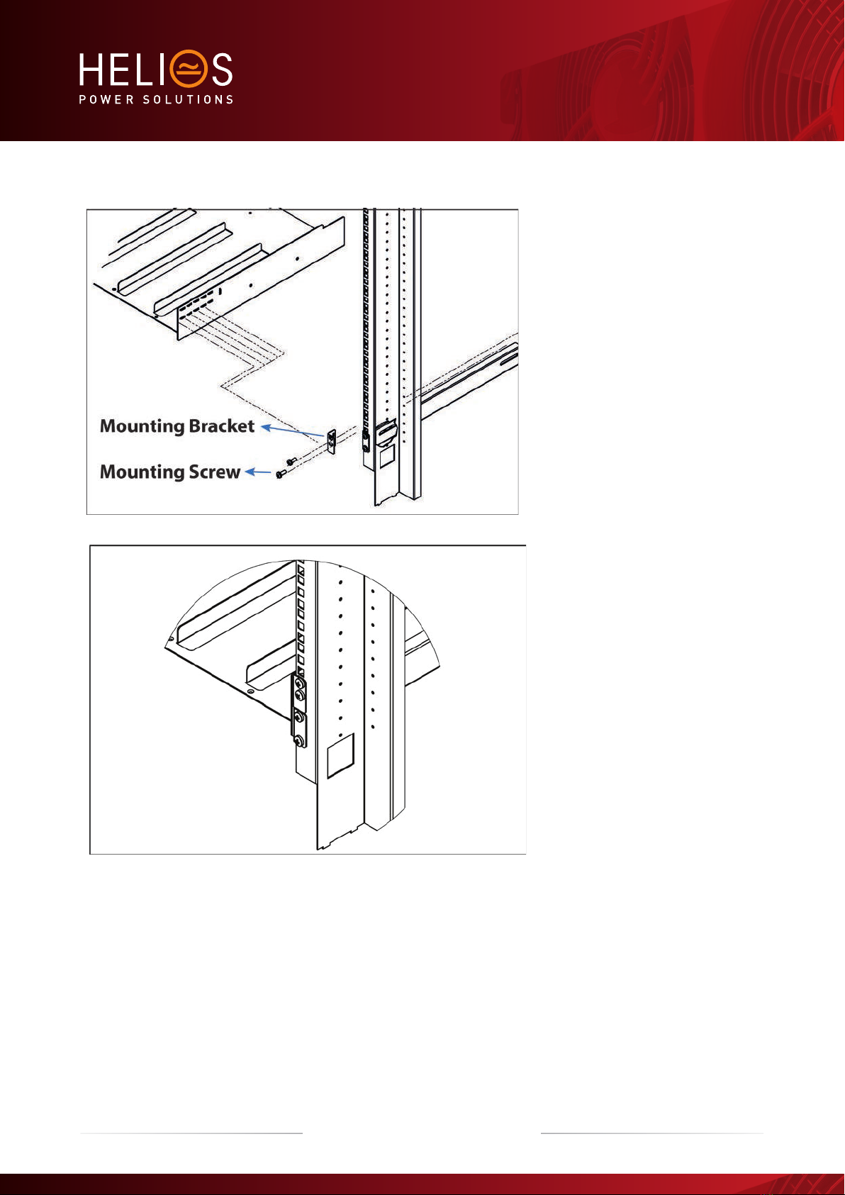
Fix cage nuts in the mounting
frame
Assemble the mounting bracket in
a suitable position.
Slide the shelf in position and
fix the shelf with the supplied
mounting screws
Finished
8.3 Electrical installation
8.3.1 Pre requisites
The sub –rack have markings for all terminations.
All cables shall be rated at Min 90 deg C.
Electrical terminations shall be tightened with 5Nm.
All connection screws are M5 x 12mm.
DC Input-Individual (per module), observe polarity.
AC Input / AC output –Common (per shelf), respect phases.
Wire all positions in the sub-rack for future expansion.
19 – Bravo ST 230 VAC– User manual – v7.3
Bravo ST Shelves Installation

Input AC / Output AC / Input DC / Signal cables shall be separated
Cable crossings shall be done in 90 deg angles.
It is recommended to install appropriate breaker at AC input and place a warning label near the breaker
stating message as “ISOLATE UNINTERRUPTIBLE POWER SUPPLY (UPS) BEFORE WORKING ON THIS CIRCUIT”.
8.3.2 Terminations
Rear Side of Bravo ST 230 VAC terminations are clearly marked in the following figure
8.3.3 Grounding
“PE CHASSIS GROUND”
PE Chassis ground shall be wired to MET or distributed earth bar connected to MET
Main protective conductor(PE) connection is made to the X2(AC IN) terminal block marked with symbol for identification.
PE must be terminated even if commercial Mains is not available and shall be connected to building or main panel ground.
Recommended Cable cross section is the size equal(min) to Neutral cable cross section. Adhere to local regulations.
Ground has to be connected in accordance with local code.
20 – Bravo ST 230 VAC– User manual – v7.3
Bravo ST Shelves Installation
Table of contents
Popular Inverter manuals by other brands


BARRON
BARRON EXITRONIX Tucson Micro Series installation instructions

Baumer
Baumer HUBNER TDP 0,2 Series Mounting and operating instructions

electroil
electroil ITTPD11W-RS-BC Operation and Maintenance Handbook

Silicon Solar
Silicon Solar TPS555-1230 instruction manual

Mission Critical
Mission Critical Xantrex Freedom SW-RVC owner's guide

HP
HP 3312A Operating and service manual


