Helios AIR1-EVH RH User manual

Elektrische Vorheizung
Electrical pre-heater
Préchauffage électrique
AIR1-EVH RH
für AIR1 RH Lüftungsgeräte
for AIR1 RH ventilation units
pour les centrales AIR1 RH
DE
EN
FR
Helios Ventilatoren
MONTAGE- UND BETRIEBSVORSCHRIFT
INSTALLATION AND OPERATING INSTRUCTIONS
NOTICE DE MONTAGE ET D’ENTRETIEN

Inhaltsverzeichnis
KAPITEL 1 ALLGEMEINE HINWEISE...........................................................Seite 2
1.0 Wichtige Informationen ................................................................ Seite 2
1.1 Warn- und Sicherheitshinweise .......................................................... Seite 2
1.2 Garantieansprüche – Haftungsausschluss.................................................. Seite 2
1.3 Vorschriften – Richtlinien ............................................................... Seite 2
1.4 Einsatzbereich – Bestimmungsgemäße Verwendung.......................................... Seite 2
1.5 Funktionsbeschreibung ................................................................ Seite 2
KAPITEL 2 INSTALLATION UND INBETRIEBNAHME..............................................Seite 3
2.0 Allgemeine Montagehinweise ........................................................... Seite 3
2.0.1 Sendungsannahme ................................................................... Seite 3
2.0.2 Einlagerung ......................................................................... Seite 3
2.0.3 Transport. .......................................................................... Seite 4
2.0.4 Demontage und Wiederaufbau .......................................................... Seite 4
2.0.5 Entsorgung ......................................................................... Seite 4
2.1 Mechanische Montage ................................................................ Seite 4
KAPITEL 3 SERVICE UND WARTUNG ..........................................................Seite 7
3.0 Service und Wartung.................................................................. Seite 7
KAPITEL 4 RESET-FUNKTION ................................................................Seite 8
4.0 Reset-Funktion ...................................................................... Seite 8
DEUTSCH
Elektrische Vorheizung AIR1-EVH RH
Montage- und Betriebsvorschrift

2
Elektrische Vorheizung AIR1-EVH RH
Montage- und Betriebsvorschrift
DE
1.0 Wichtige Informationen
Zur Sicherstellung einer einwandfreien Funktion und zur eigenen Sicherheit sind alle nachstehenden Vorschriften genau
durchzulesen und zu beachten. Im Wartungsteil sind wichtige Informationen über erforderliche Reinigungs- und War-
tungstätigkeiten aufgeführt. Die Reinigungs- und Wartungsarbeiten dürfen nur von qualifizierten Elektrofachkräften
durchgeführt werden. Das Kapitel „Installation und Inbetriebnahme“ mit wichtigen Installationshinweisen und Geräte-
grundeinstellungen richtet sich an den Fachinstallateur.
mDer Elektroanschluss muss bis zur endgültigen Montage allpolig vom Netz getrennt sein!
Dieses Gerät ist nicht für den Gebrauch durch Personen (einschließlich Kinder) mit eingeschränkter körper-
licher, sensorischer oder geistiger Leistungsfähigkeit oder mangelnder Erfahrung und Kenntnis bestimmt, es
sei denn, sie wurden von einer für ihre Sicherheit verantwortlichen Person beaufsichtigt oder unterwiesen.
Kinder sollten beaufsichtigt werden, um sicherzustellen, dass sie nicht mit dem Gerät spielen.
Die Montage- und Betriebsvorschrift als Referenz am Gerät aufbewahren. Nach der Endmontage muss dem Betreiber
(Mieter/Eigentümer) das Dokument ausgehändigt werden.
1.1 Warn- und Sicherheitshinweise
Nebenstehendes Symbol ist ein sicherheitstechnischer Warnhinweis. Alle Sicherheitsvorschriften bzw. Symbole
müssen unbedingt beachtet werden, damit jegliche Gefahrensituation vermieden wird.
m GEFAHR
Warnung vor Gefahren, die bei Missachtung der Maßnahmen unmittelbar zu Tod oder schweren Verletzungen
führen.
m WARNUNG
Warnung vor Gefahren, die bei Missachtung der Maßnahmen zu Tod oder schweren Verletzungen führen können.
m VORSICHT
Warnung vor Gefahren, die bei Missachtung der Maßnahmen zu Verletzungen führen können.
ACHTUNG
Warnung vor Gefahren, die bei Missachtung der Maßnahmen zu Sachschäden führen können.
1.2 Garantieansprüche – Haftungsausschluss
Wenn die nachfolgenden Ausführungen nicht beachtet werden, entfällt die Gewährleistung. Gleiches gilt für Haftungs-
ansprüche an den Hersteller.
Der Gebrauch von Zubehörteilen, die nicht von Helios empfohlen oder angeboten werden, ist nicht statthaft. Eventuell
auftretende Schäden unterliegen nicht der Gewährleistung.
1.3 Vorschriften – Richtlinien
Bei ordnungsgemäßer Installation und bestimmungsgemäßem Betrieb entspricht das Gerät den zum Zeitpunkt seiner
Herstellung gültigen Vorschriften und CE-Richtlinien.
1.4 Einsatzbereich – Bestimmungsgemäße Verwendung
Die elektrische Vorheizung ist ausschließlich als Zubehör für Lüftungsgeräte der AIR1-Serie RH bestimmt.
Zur bestimmungsgemäßen Verwendung gehört auch die Beachtung der Betriebsanleitung und der Anweisungen des
Herstellers des Lüftungsgeräts sowie der von HELIOS festgelegten Inspektions- und Wartungsintervalle.
Ein bestimmungsfremder Einsatz ist nicht zulässig!
1.5 Funktionsbeschreibung
Die elektrische Vorheizung wird für die Erhöhung der Außenluft-Temperatur verwendet. Die elektrische Vorheizung ver-
meidet ein Einfrieren des Rotationswärmetauschers! Diese wird schrittweise gesteuert, um den Energieverbrauch zu
reduzieren.
Die Vorheizung ist mit zwei Sicherheitstemperaturbegrenzern ausgerüstet. Die Sicherheitstemperaturbegrenzer
(Auto-Reset = Auslösetemp. +70 °C) und (manuelle Rückstellung = Auslösetemp. +90 °C) sind in Reihe angeschlossen.
Nachdem der Sicherheitstemperaturbegrenzer auslöst, wird die Vorheizung von der Netzstromversorgung getrennt
und auf dem Bedienelement wird eine Fehlermeldung ausgegeben.
– Vorheizung aktivieren/deaktivieren
Der Benutzer/Installateur kann die Vorheizung aktivieren/deaktivieren (s. Kapitel für Inbetriebnahme)
Die Vorheizung funktioniert nur, wenn der Zuluftventilator reibungslos läuft. Wenn das Gerät entweder in den Stand-
by-Modus umgeschaltet oder ausgeschaltet wird, dann wird die Vorheizung sofort deaktiviert. Der Zuluftventilator hat
eine Nachlaufzeit von 90 Sekunden.
Die technischen Daten und Abmessungen der elektrischen Vorheizungen sind in den folgenden Tabellen ersichtlich.
KAPITEL 1
ALLGEMEINE HINWEISE
m GEFAHR
m
m GEFAHR
m WARNUNG
m VORSICHT
ACHTUNG

3
Elektrische Vorheizung AIR1-EVH RH
Montage- und Betriebsvorschrift
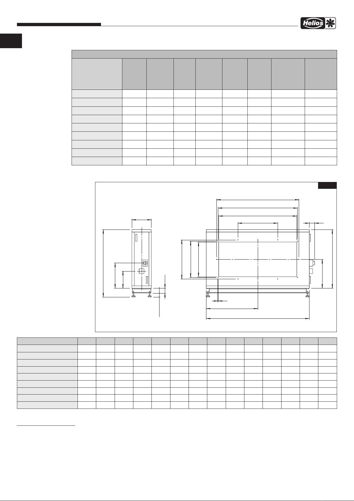
Abmessungen elektrische Vorheizung
2.0 Allgemeine Montagehinweise
2.0.1 Sendungsannahme
Die Sendung ist sofort bei Anlieferung auf Beschädigungen und Typenrichtigkeit zu prüfen. Falls Schäden vorliegen,
umgehend Schadensmeldung unter Hinzuziehung des Transportunternehmens veranlassen. Bei nicht fristgerechter
Reklamation gehen evtl. Ansprüche verloren.
2.0.2 Einlagerung
Bei Einlagerung über einen längeren Zeitraum sind zur Verhinderung schädlicher Einwirkungen folgende Maßnahmen
zu treffen:
Schutz durch trockene, luft- und staubdichte Verpackung (Kunststoffbeutel mit Trockenmittel und Feuchtigkeitsindi-
katoren). Der Lagerort muss erschütterungsfrei, wassergeschützt und frei von übermäßigen Temperaturschwankun-
AIR1 RH elektrische Vorheizung
Gerätetype Leistung
max.
(kW)
Strom-
aufnahme
max. (A)
Phasen Betriebs-
spannung
(V)
Frequenz
(Hz)
Gewicht
(kg)
Schutzart
(ohne Wetter-
schutzdach)
Schutzart
(mit Wetter-
schutzdach)
AIR1-EVH RH 1500 4,2 6,06 3 400 50 65 31 54
AIR1-EVH RH 2000 5,8 8,37 3 400 50 70 31 54
AIR1-EVH RH 3000 9,1 13,13 3 400 50 80 31 54
AIR1-EVH RH 5000 15,6 22,52 3 400 50 100 31 54
AIR1-EVH RH 6000 18,1 26,13 3 400 50 115 31 54
AIR1-EVH RH 8000 22 31,75 3 400 50 140 31 54
AIR1-EVH RH 9500 22 31,75 3 400 50 155 31 54
AIR1-EVH RH 12000 22 31,75 3 400 50 170 31 54
AIR1-EVH RH 15000 22 31,75 3 400 50 190 31 54
100
max. 80
400
max. E
I
K
T
W
R
X
U
S
V
110
B
O
C
M8
P
Maße (mm)
Art.-Nr.
Type
B
C
E
I
K
O
P
R
S
T
U
V
W
X
01262
AIR1-EVH RH 1500
520 760 700 200 173 380 265 378 338 350 310
---
01710
AIR1-EVH RH 2000
580 860 760 250 173 430 295 498 338 470 310
---
01711
AIR1-EVH RH 3000
640 970 820 250 173 485 300 608 438 580 410
---
01791
AIR1-EVH RH 5000
780 1240 960 300 465 620 375 883 438 855 410 498
- -
01792
AIR1-EVH RH 6000
830 1360 1010 300 465 680 400 883 438 855 410 498
- -
01819
AIR1-EVH RH 8000
950 1610 1130 350 515 805 465 1083 438 1055 410 498
361,1
-
01830
AIR1-EVH RH 9500
1000 1710 1180 350 515 855 490 1228 438 1200 410 498
409,4
-
01871
AIR1-EVH RH 12000
1080 1860 1260 350 515 930 530 1503 538 1475 510 598
501,1
1563
01883
AIR1-EVH RH 15000
1200 2110 1380 350 515 1055 590 1628 738 1600 710 798
814,2
1688
Abb.1
Type B C E I K O P R S T U V W X
AIR1-EVH RH 1500 520 760 700 200 173 380 265 378 338 350 310 – – –
AIR1-EVH RH 2000 580 860 760 250 173 430 295 498 338 470 310 – – –
AIR1-EVH RH 3000 640 970 820 250 173 485 320 608 438 580 410 498 – –
AIR1-EVH RH 5000 780 1240 960 300 465 620 375 883 438 855 410 498 – –
AIR1-EVH RH 6000 830 1360 1010 300 465 680 400 883 438 855 410 498 – –
AIR1-EVH RH 8000 950 1610 1130 350 515 805 465 1083 438 1055 410 498 361,1 –
AIR1-EVH RH 9500 1000 1710 1180 350 515 855 490 1228 438 1200 410 498 409,4 –
AIR1-EVH RH 12000 1080 1860 1260 350 515 930 530 1503 538 1475 510 598 501,1 1563
AIR1-EVH RH 15000 1200 2110 1380 350 515 1055 590 1628 738 1600 710 798 814,2 1688
KAPITEL 2
INSTALLATION UND
INBETRIEBNAHME
DE

4
Elektrische Vorheizung AIR1-EVH RH
Montage- und Betriebsvorschrift
gen sein (Umgebungstemperaturbegrenzung: min. 0 °C /max. +40 °C). Schäden, deren Ursprung in unsachgemä-
ßem Transport, unsachgemäßer Einlagerung oder Inbetriebnahme liegen, sind nachweisbar und unterliegen nicht der
Gewährleistung.
2.0.3 Transport
Der Transport muss sorgfältig durchgeführt werden. Es wird empfohlen das Gerät bis zur Aufstellung in der Originalver-
packung zu belassen, um mögliche Beschädigungen und Verschmutzungen zu vermeiden.
Der Transport muss von geschultem und erfahrenem Personal durchgeführt werden und es müssen die notwendigen
Sicherheitsvorkehrungen getroffen werden, um ein Umkippen und Verrutschen des Geräts zu verhindern. Beim Trans-
port des Geräts ist darauf zu achten, dass das Gewicht gleichmäßig verteilt wird.
mPersonen- und/oder Sachschaden durch unsachgemäßen Transport!
Es muss sichergestellt sein, dass das Transport-/Hebegerät geeignet ist, um das erforderliche Gewicht und die erfor-
derliche Größe zu transportieren.
– Sicherstellen, dass das Gerät fest sitzt, bevor es angehoben wird.
Sachschaden durch zu hohe Last!
Vor dem Entladen sicherstellen, dass die Transport-/Hubvorrichtungen ausreichende Kapazität für das erforderliche
Gewicht haben.
m Gefahr von Personen- und Sachschäden!
Die Packeinheiten können einen außer-mittigen Schwerpunkt aufweisen. Wenn die Packeinheit nicht korrekt
angehoben wird, kann diese umkippen. Herunterfallende oder umkippende Packeinheiten können eine schwer-
wiegende Körperverletzung verursachen.
Während des Anhebens, muss der Gewichtsschwerpunkt der Packeinheiten senkrecht unter dem Kranhaken
sein.
2.0.4 Demontage und Wiederaufbau
m Lebensgefahr durch Stromschlag!
Ein Stromschlag kann zu Tod oder schweren Verletzungen führen.
– Sicherstellen, dass das Gerät spannungsfrei und isoliert ist. Gerät erden und kurzschließen, benachbarte spannungs-
führende Komponenten abschirmen.
– Vor der Demontage oder dem Wiederaufbau muss das Gerät vom Stromnetz getrennt sein.
m Gefahr von Personen- und Sachschäden!
Die Demontage und der Wiederaufbau des Geräts gehören nicht zur routinemäßigen Wartung.
– Die Demontage und der Wiederaufbau des Geräts dürfen nur von qualifiziertem Fachpersonal durchgeführt werden.
2.0.5 Entsorgung
m Lebensgefahr durch Stromschlag!
Ein Stromschlag kann zu Tod oder schweren Verletzungen führen.
– Sicherstellen, dass das Gerät spannungsfrei und isoliert ist. Gerät erden und kurzschließen, benachbarte spannungs-
führende Komponenten abschirmen.
Alle Komponenten müssen umweltgerecht, gemäß den örtlichen Vorschriften, Praktiken und Umweltvorschriften, ent-
sorgt werden.
Ein autorisierter Fachbetrieb für die Abfallbehandlung muss das Gerät oder die einzelnen Komponenten entsorgen. Der
beauftragte Auftragnehmer muss sicherstellen, dass die Komponenten nach Materialarten getrennt werden.
2.1 Mechanische Montage
mLebensgefahr durch Stromschlag!
Die Installation und der Anschluss des Geräts dürfen nur von qualifiziertem Fachpersonal durchgeführt werden. Die
elektrischen Anschlüsse müssen von einer Person durchgeführt werden, die über eine entsprechende Berufsausbil-
dung und Erfahrung in den einschlägigen Unfallverhütungsvorschriften sowie den allgemein anerkannten Sicherheits-
und Gesundheitsschutzvorschriften verfügt und berechtigt ist, Arbeiten am Gerät durchzuführen.
Gefährdung durch elektrischen Schlag, bewegliche Teile (Gebläse) und heiße Oberflächen.
Elektrische Vorheizung
Vor allen Wartungs- und Installationsarbeiten oder vor Öffnen des Klemmenkastens ist das Gerät allpolig vom
Netz zu trennen! Der elektrische Anschluss darf nur von einer autorisierten Elektrofachkraft entsprechend den
nachstehenden Anschlussplänen ausgeführt werden. Der Elektroanschluss muss bis zur finalen Montage all-
polig vom Netz getrennt sein!
Die elektirsche Vorheizung ist für die Installation im Freien nur in Verbindung mit dem passenden Wetter-
schutzdach und einer Außenluft-Ansaughaube geeignet!
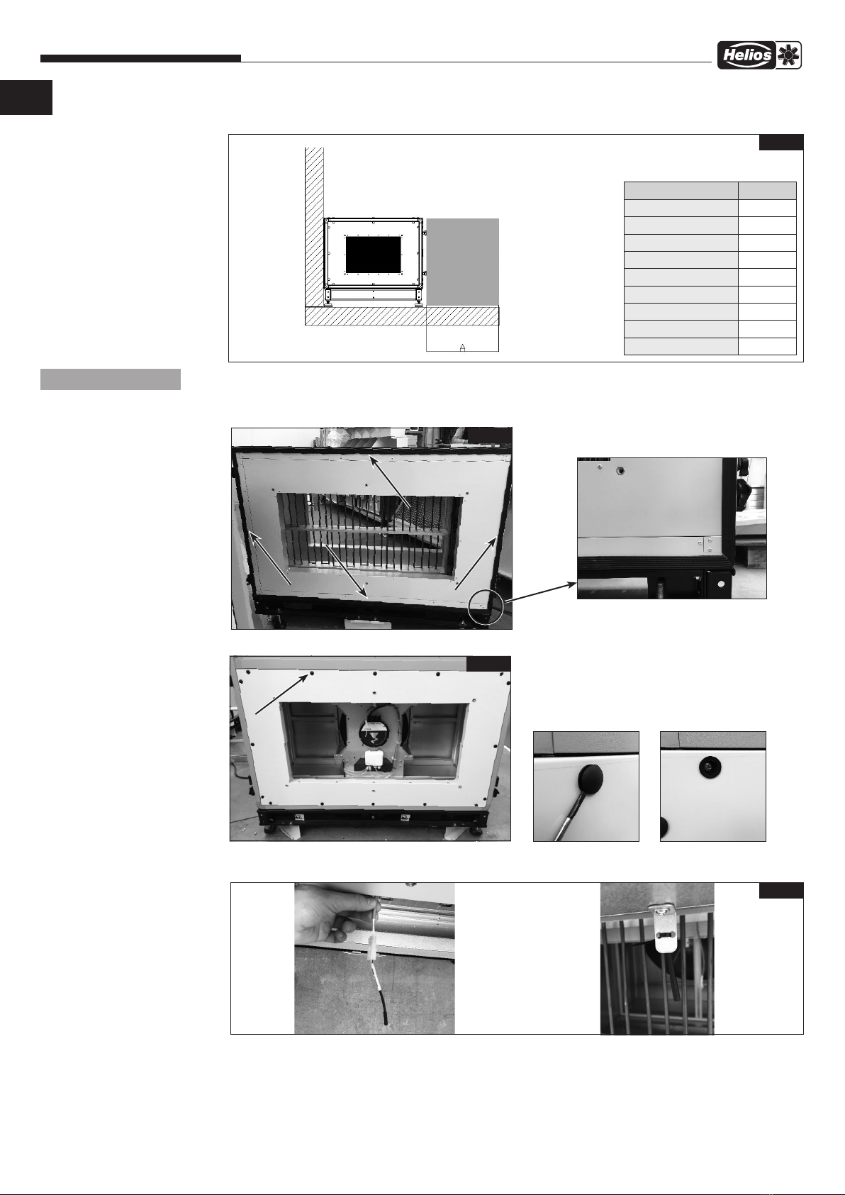
Einbauort
Die Einbausituation muss einen Berührschutz gegen Hineingreifen in das Heizregister sicherstellen. Dies ist bspw.
mittels Kanälen oder der Ansaughaube Außenluft möglich.
Bei der Geräteinstallation müssen folgende Kriterien beachtet werden, um eine leichte Zugänglichkeit für Wartungs-
und Instandhaltungsarbeiten zu gewährleisten. (Abb. 2).
A: Mindestabstand für die Wartung der elektrischen Vorheizung.
m GEFAHR
ACHTUNG
m GEFAHR
m GEFAHR
m WARNUNG
m GEFAHR
m GEFAHR
m GEFAHR
DE

5
Elektrische Vorheizung AIR1-EVH RH
Montage- und Betriebsvorschrift
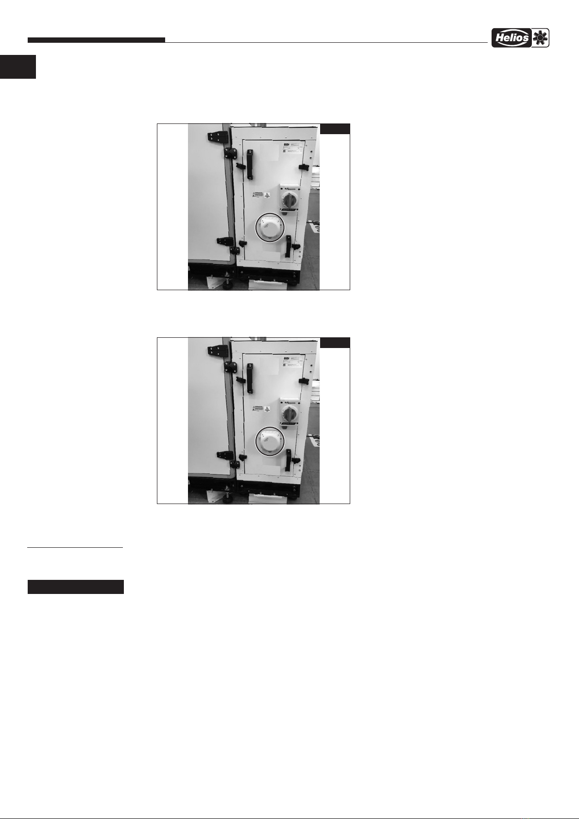
Die elektrische Vorheizung kann in beide Luftrichtungen eingesetzt werden. Vor der Montage die Serviceseite festlegen
und die Vorheizung entsprechend ausrichten.
1. Dichtungsstreifen dort auftragen, wo das Modul mit dem Gerät aneinandergefügt wird (s. Abb. 3).
2. Schraubenabdeckungen am Gerät entfernen, bevor das Modul installiert wird (s. Abb. 4).
3. Den Temperatursensor (im Lieferumfang enthalten) an die Außenluftseite der Vorheizung anschließen. Den Sensor
mit einem Kabelbinder auf dem Blechhalter befestigen (s. Abb. 5).
Abb.2
Type A (mm)
AIR1-EVH RH 1500 960
AIR1-EVH RH 2000 1060
AIR1-EVH RH 3000 1170
AIR1-EVH RH 5000 1440
AIR1-EVH RH 6000 1560
AIR1-EVH RH 8000 1810
AIR1-EVH RH 9500 1910
AIR1-EVH RH 12000 2060
AIR1-EVH RH 15000 2310
HINWEIS
Abb.3
Abb.4
Abb.5
DE

6
Elektrische Vorheizung AIR1-EVH RH
Montage- und Betriebsvorschrift
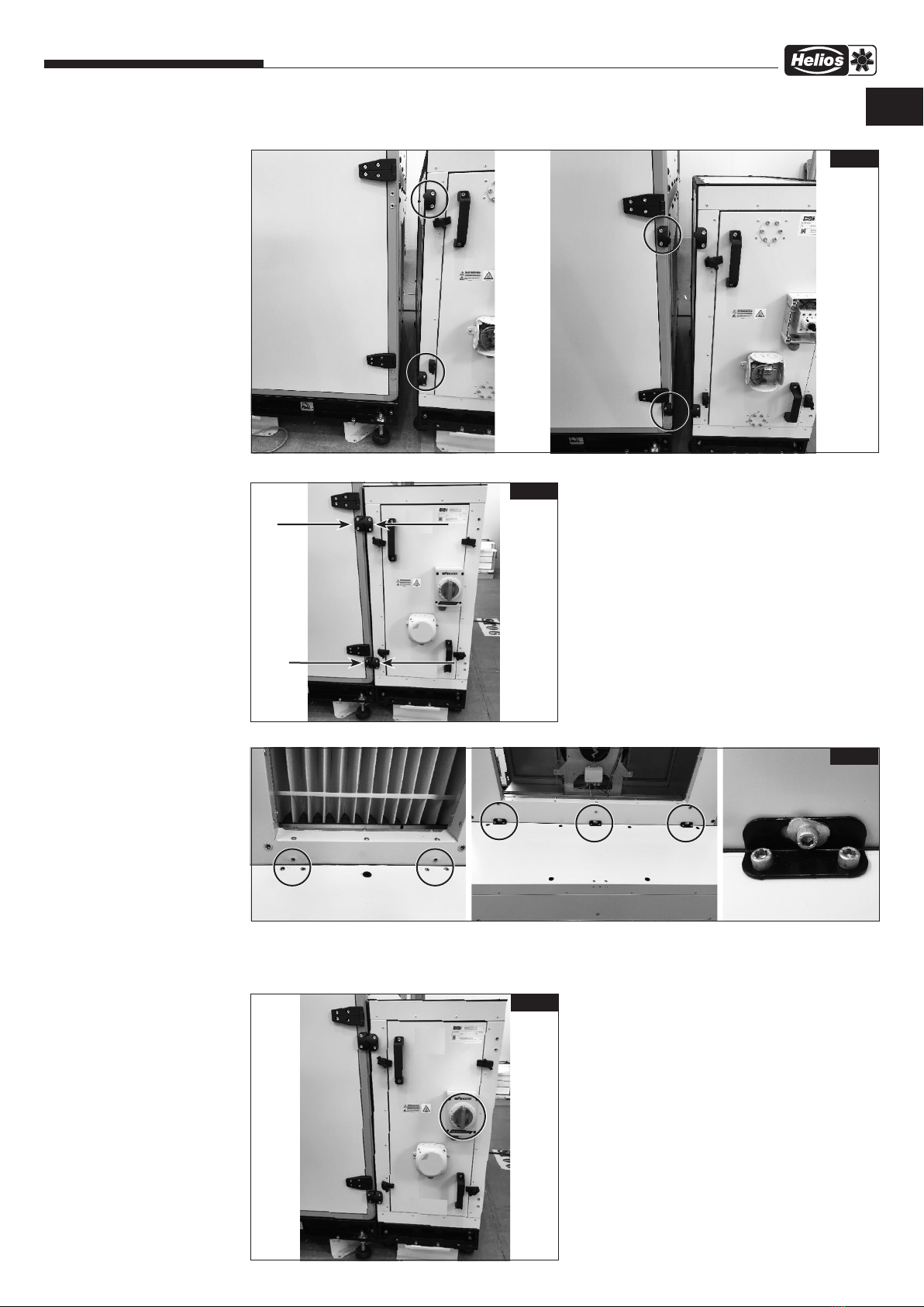
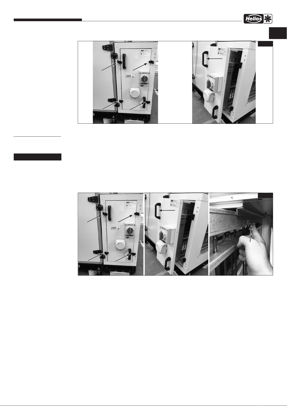
4. Die Modulverbindungsteile an das AIR1-Gerät und die Vorheizung montieren (s. Abb. 6).
5. Die Schrauben fest anziehen. (Abb. 7).
6. Blechteile auf der Vorheizung montieren. AIR1-Gerät wie folgt mit der Vorheizung verbinden (s. Abb. 8).
7. Abdeckung des Hauptschalters öffnen. Leitungsquerschnitt, der für den Stromanschluss verwendet wird, festlegen.
Die Leitung an die entsprechenden Klemmen anschließen und die Hauptschalterabdeckung schließen (s. Abb. 9).
Hierzu die entsprechenden Anschlusspläne in der Montage- und Betriebsvorschrift des AIR1 RH Geräts beachten!
Abb.6
Abb.7
Abb.8
Abb.9
DE
7
Elektrische Vorheizung AIR1-EVH RH
Montage- und Betriebsvorschrift
8. Abdeckung des Klemmenkastens öffnen. Die Signalleitungen an die Klemmen anschließen und die Abdeckung des
Klemmenkastens schließen (s. Abb. 10).
Hierzu die entsprechenden Anschlusspläne in der Montage- und Betriebsvorschrift des AIR1 RH Geräts beach-
ten!
9. Das andere Leitungsende vom Klemmenkasten der elektrischen Vorheizung mit der korrekten Anschlussklemme im
Klemmenkasten des AIR1-Geräts anschließen.
Hierzu die entsprechenden Anschlusspläne in der Montage- und Betriebsvorschrift des AIR1 RH Geräts beach-
ten!
10.Nach der Installation des Heizregisters die Einstellungen im Inbetriebnahme-Assistenten vornehmen. Hierzu das
entsprechende Kapitel der Montage- und Betriebsvorschrift des jeweiligen AIR1-Lüftungsgeräts beachten.
3.0 Service und Wartung
Reinigungs- und Wartungsarbeiten dürfen nur von einer Elektrofachkraft durchgeführt werden.
m Lebensgefahr!
Vor allen Wartungs- und Installationsarbeiten sowie vor Öffnen des Klemmenkastens ist das Gerät allpolig vom
Netz zu trennen!
Gefährdung durch elektrischen Schlag, bewegliche Teile (Gebläse) und heiße Oberflächen.
Die elektrische Vorheizung muss alle 6 Monate auf Schmutz und Schäden überprüft werden. Wenn sich Schmutz und
Staub auf der elektrischen Vorheizung befinden, können diese mit Luft entfernt werden.
– Bei der Reinigung ist darauf zu achten, dass die elektrische Nachheizung nicht beschädigt wird.
– Sensoranschluss trennen bevor die elektrische Vorheizung entfernt wird.
– Die Schrauben lösen und die elektrische Vorheizung entfernen.
Abb.10
Abb.10
KAPITEL 3
SERVICE UND WARTUNG
m WARNUNG
DE

8
Elektrische Vorheizung AIR1-EVH RH
Montage- und Betriebsvorschrift
4.0 Reset-Funktion
m Lebensgefahr!
Vor allen Wartungs- und Installationsarbeiten sowie vor Öffnen des Klemmenkastens ist das Gerät allpolig vom
Netz zu trennen!
Gefährdung durch elektrischen Schlag, bewegliche Teile (Gebläse) und heiße Oberflächen.
Wartung erst nach 3 Minuten Wartezeit durchführen!
Der manuelle Reset-Schalter befindet sich direkt an der elektrischen Vorheizung.
Elektrische Vorheizung
1. Die Schrauben lösen und die elektrische Heizung entfernen, um zu dem Reset-Schalter zu gelangen.
2. Den Reset-Schalter nach oben drücken, um eine manuelle Rückstellung zu erzielen (Abb. 12).
Manuelle Rückstellung: Die manuelle Rückstelltemperatur ist 90 °C. Wenn die Sicherheitstemperatur 90 °C erreicht
ist, wird der Sicherheitstemperaturbegrenzer ausgelöst und die Vorheizung wird von der Netzstromversorgung getrennt.
Falls die Manuelle Rückstellung aktiviert ist, besteht höchstwahrscheinlich ein Problem mit der Heizung.
Automatische Rückstellung: Die automatische Rückstelltemperatur ist 70 °C. Wenn die Sicherheitstemperatur 70 °C
erreicht ist, wird der Sicherheitstemperaturbegrenzer ausgelöst und die Vorheizung wird von der Netzstromversorgung
getrennt. Wenn die Temperatur unter 70 °C absinkt, schaltet sich die elektrische Heizung automatisch an.
Abb.11
KAPITEL 4
RESET-FUNKTION
m WARNUNG
Abb.12
DE

Table of Contents
CHAPTER 1 GENERAL INFORMATION .........................................................Page 2
1.0 Important information .................................................................Page 2
1.1 Warning and safety instructions..........................................................Page 2
1.2 Warranty claims – Exclusion of liability .....................................................Page 2
1.3 Regulations - Guidelines ...............................................................Page 2
1.4 Area of application – Intended use........................................................Page 2
1.5 Functional description .................................................................Page 2
CHAPTER 2 INSTALLATION AND COMMISSIONING..............................................Page 3
2.0 General installation instructions ..........................................................Page 3
2.0.1 Receipt ............................................................................Page 3
2.0.2 Storage ............................................................................Page 3
2.0.3 Shipping............................................................................Page 4
2.0.4 Disassembly and re-assembly ...........................................................Page 4
2.0.5 Disposal ...........................................................................Page 4
2.1 Mechanical assembly .................................................................Page 4
CHAPTER 3 SERVICE AND MAINTENANCE .....................................................Page 7
3.0 Service and maintenance ..............................................................Page 7
CHAPTER 4 RESET FUNCTION ...............................................................Page 8
4.0 Reset function .......................................................................Page 8
ENGLISH
Electrical pre-heater AIR1-EVH RH
Installation and Operating Instructions

2
Electrical pre-heater AIR1-EVH RH
Installation and Operating Instructions
EN
1.0 Important information
In order to ensure safety and correct operation and for your own safety, please read and observe the following inst-
ructions carefully before proceeding. Important information on filter changes and necessary cleaning and maintenance
activities is specified in the maintenance section. Filter changes are usually carried out by the user. Further cleaning and
maintenance work may only be carried out by qualified electricians. The chapter “Installation and commissioning” with
important installation information and basic unit settings is intended for the specialist installer.
mThe electrical connection must be fully isolated from the mains power supply until final assembly!
This unit is not intended for use by persons (including children) with reduced physical, sensory or mental
capabilities, or lack of experience and knowledge, unless they have been given supervision or instruction con-
cerning use of the unit by a person responsible for their safety. Children should be supervised to ensure that
they do not play with the unit.
Keep the installation and operating instructions with the unit for reference. The document must be handed to the ope-
rator (tenant/owner) after final assembly.
1.1 Warning and safety instructions
The adjacent symbol is a safety-relevant prominent warning label. All safety regulations and/or symbols must be
absolutely adhered to, so that any dangerous situation is avoided.
m DANGER
Indicates dangers which will directly result in death or serious injury if the safety instruction is not followed.
m WARNING
Indicates dangers which will result in death or serious injury if the safety instruction is not followed.
m CAUTION
Indicates dangers which can result in injuries if the safety instruction is not followed.
ATTENTION
Indicates dangers which can result in material damage if the safety instruction is not followed.
1.2 Warranty claims – Exclusion of liability
If the preceding instructions are not observed, all warranty claims shall be excluded. This also applies for liability claims
against the manufacturer.
The use of accessories, which are not recommended or offered by Helios, is not permitted. Any possible damages are
not covered by the warranty.
1.3 Regulations - Guidelines
If the product is installed correctly and used according to its intended purpose. conforms to all applicable provisions
and CE guidelines at its date of manufacture.
1.4 Area of application – Intended use
The electrical auxiliary heater is exclusively intended as an accessory for ventilation units in AIR1 series RH.
The intended use also includes observance of the operating manual as well as the inspection and maintenance intervals
stipulated by HELIOS.
Any use other than the intended use is prohibited!
1.5 Functional description
The electrical pre-heater is used to increase the outside air temperature. The electrical pre-heater prevents the rotary
heat exchanger from freezing! This is controlled gradually to reduce the energy consumption.
The pre-heater is equipped with two safety temperature limiters. The safety temperature limiters (Auto reset = trigger
temp. +70 °C) and (manual reset = trigger temp. +90 °C) are connected in series. Once a safety temperature limiter is
triggered, the electrical heating register will be disconnected from the power supply and an error will be displayed on
the controller.
– Activate/deactivate pre-heater
The user/installer can activate/deactivate the pre-heater (see chapter for commissioning)
The pre-heater will only operate if the supply air fan is running smoothly. If the unit is either switched to standby mode
or deactivated, then the pre-heater will immediately deactivate. The supply air fan has an overrun time of 90 seconds.
The technical data and dimensions of the electrical pre-heaters are shown in the following table.
CHAPTER 1
GENERAL INFORMATION
m DANGER
m
m DANGER
m WARNING
m CAUTION
ATTENTION
3
Electrical pre-heater AIR1-EVH RH
Installation and Operating Instructions
Dimensions Electrical pre-heater
2.0 General installation instructions
2.0.1 Receipt
Please check delivery immediately on receipt for accuracy and damage. If damaged, please notify the carrier immedia-
tely. In case of delayed notification, any possible claim may be void.
2.0.2 Storage
When storing for a prolonged time, the following steps are to be taken to avoid damaging influences:
Protection by dry, airtight and dust-proof packaging (plastic bag with desiccant and humidity indicators). The storage
place must be waterproof, vibration-free and free of temperature variations (ambient temperature limit: min. 0 °C /max.
AIR1 RH electrical pre-heater
Unit type Power
max.
(kW)
Power
consump-
tion max.
(A)
Phases Operating
voltage
(V)
Frequen-
cy (Hz)
Weight
(kg)
Protection
category
(w/o weather
protection
cover)
Protection
category
(w/ weather
protection
cover)
AIR1-EVH RH 1500 4.2 6.06 3 400 50 65 31 54
AIR1-EVH RH 2000 5.8 8.37 3 400 50 70 31 54
AIR1-EVH RH 3000 9.1 13.13 3 400 50 80 31 54
AIR1-EVH RH 5000 15.6 22.52 3 400 50 100 31 54
AIR1-EVH RH 6000 18.1 26.13 3 400 50 115 31 54
AIR1-EVH RH 8000 22 31.75 3 400 50 140 31 54
AIR1-EVH RH 9500 22 31.75 3 400 50 155 31 54
AIR1-EVH RH 12000 22 31,75 3 400 50 170 31 54
AIR1-EVH RH 15000 22 31,75 3 400 50 190 31 54
100
max. 80
400
max. E
I
K
T
W
R
X
U
S
V
110
B
O
C
M8
P
Maße (mm)
Art.-Nr.
Type
B
C
E
I
K
O
P
R
S
T
U
V
W
X
01262
AIR1-EVH RH 1500
520 760 700 200 173 380 265 378 338 350 310
---
01710
AIR1-EVH RH 2000
580 860 760 250 173 430 295 498 338 470 310
---
01711
AIR1-EVH RH 3000
640 970 820 250 173 485 300 608 438 580 410
---
01791
AIR1-EVH RH 5000
780 1240 960 300 465 620 375 883 438 855 410 498
- -
01792
AIR1-EVH RH 6000
830 1360 1010 300 465 680 400 883 438 855 410 498
- -
01819
AIR1-EVH RH 8000
950 1610 1130 350 515 805 465 1083 438 1055 410 498
361,1
-
01830
AIR1-EVH RH 9500
1000 1710 1180 350 515 855 490 1228 438 1200 410 498
409,4
-
01871
AIR1-EVH RH 12000
1080 1860 1260 350 515 930 530 1503 538 1475 510 598
501,1
1563
01883
AIR1-EVH RH 15000
1200 2110 1380 350 515 1055 590 1628 738 1600 710 798
814,2
1688
Fig.1
Type B C E I K O P R S T U V W X
AIR1-EVH RH 1500 520 760 700 200 173 380 265 378 338 350 310 – – –
AIR1-EVH RH 2000 580 860 760 250 173 430 295 498 338 470 310 – – –
AIR1-EVH RH 3000 640 970 820 250 173 485 320 608 438 580 410 498 – –
AIR1-EVH RH 5000 780 1240 960 300 465 620 375 883 438 855 410 498 – –
AIR1-EVH RH 6000 830 1360 1010 300 465 680 400 883 438 855 410 498 – –
AIR1-EVH RH 8000 950 1610 1130 350 515 805 465 1083 438 1055 410 498 361.1 –
AIR1-EVH RH 9500 1000 1710 1180 350 515 855 490 1228 438 1200 410 498 409.4 –
AIR1-EVH RH 12000 1080 1860 1260 350 515 930 530 1503 538 1475 510 598 501.1 1563
AIR1-EVH RH 15000 1200 2110 1380 350 515 1055 590 1628 738 1600 710 798 814.2 1688
CHAPTER 2
INSTALLATION AND
COMMISSIONING
EN

4
Electrical pre-heater AIR1-EVH RH
Installation and Operating Instructions
+40 °C). Damages due to improper transportation, storage or commissioning must be verified and are not liable for
warranty.
2.0.3 Shipping
The shipping must be carried out carefully. It is recommended to leave the unit in the original packaging until installation
to avoid possible damages and contamination.
The shipping must be carried out by trained and experienced personnel and the necessary safety precautions should
be taken to prevent overturning and slipping of the device. it should be ensured that the weight is evenly distributed
when shipping the unit.
mPersonal injury and/or material damage due to incorrect shipping!
It must be ensured that the means of transport/lifting is suitable to accommodate to the required weight and size
capacity.
– Make sure that the unit is firmly seated before lifting it.
Material damage due to excessive load!
Before off-loading the units, please ensure that the means of transport/lifting have sufficient capacity for the required
weight.
m Risk of personal injury and material damage!
The package units may have an eccentric centre of gravity. If the package unit is incorrectly lifted, it can tip
over. Falling or tipping package units can cause serious personal injury.
When lifting, the centre of gravity of the package unit must be vertically beneath the crane hook.
2.0.4 Disassembly and re-assembly
m Danger to life due to electric shock!
An electric shock can result in death or serious injury.
– Ensure that the unit is voltage-free and isolated from the mains power supply. Ground and short circuit the unit, shield
neighbouring live components.
– The unit must be isolated from the mains power supply before disassembly or re-assembly.
m Risk of personal injury and material damage!
The disassembly and re-assembly of the unit are not part of routine maintenance.
– The disassembly and re-assembly of the unit may only be carried out by qualified specialist personnel.
Risk of material damage when installing heating and cooling registers!
The following must be taken into account when installing heating and cooling registers:
– Close all hydraulic stop valves.
– Isolate all connections and ensure that the unit is leak-free with regard to oil and refrigerants.
–Since the diameter of the heating and cooling pipes is small, water may remain in the register after emptying. For
safety reasons, compressed air should be blown through the system to remove the remaining water.
2.0.5 Disposal
m Danger to life due to electric shock!
An electric shock can result in death or serious injury.
– Ensure that the unit is voltage-free and isolated from the mains power supply. Ground and short circuit the unit, shield
neighbouring live components.
Dispose of all components and filters and disused operating materials (e.g. refrigerants) in an environmentally-friendly
manner in accordance with the local codes, practices and environmental regulations.
An authorised specialist waste processing company must dispose of the unit or the individual components. The appo-
inted contractor must ensure that the components are separated according to material types.
2.1 Mechanical assembly
mDanger to life due to electric shock!
The installation and connection of the unit may only be carried out by qualified specialist personnel. The electrical con-
nections must be carried out by a person who has proper professional training and experience in the relevant accident
prevention regulations, as well as other generally recognised safety and occupational health codes, with authorisation
to perform work on the unit.
Risk of injury due to electric shock, moving parts (fans) and hot surfaces.
Electrical pre-heater
The unit must be fully isolated from the mains power supply before all maintenance and installation work and
opening the terminal compartment! The electrical connections must be carried out in accordance with the fol-
lowing wiring diagrams and must only be carried out by qualified electricians. The electrical connection must
be fully isolated until the final assembly!
The electrical pre-heater is only suitable for installation outside in combination with the matching weather pro-
tection cover and an outside air intake hood!
Assembly area
The assembly position must ensure protection against reaching into the heating register. E.g. this is possible using
ducts or the outside air intake hood.
When installing the unit, the following criteria must be observed when installing the unit to ensure easy accessibility for
maintenance and maintenance work (Fig. 2).
m DANGER
ATTENTION
m DANGER
m DANGER
m WARNING
ATTENTION
m DANGER
m DANGER
m DANGER
EN
5
Electrical pre-heater AIR1-EVH RH
Installation and Operating Instructions
A: Minimum distance for servicing the electrical pre-heater.
The electrical pre-heater can be used in both air flow directions. Determine the service side and align the pre-heater
accordingly before assembly.
1. Apply sealing strips where the module joins the unit (see Fig. 3).
2. Remove screw covers on the unit before installing the module (see Fig. 4).
3. Connect the temperature sensor (included in delivery) to the outdoor side of the pre-heater. Fasten the sensor cable
to the sheet metal part with a cable tie (see Fig. 5).
Fig.2
Type A (mm)
AIR1-EVH RH 1500 960
AIR1-EVH RH 2000 1060
AIR1-EVH RH 3000 1170
AIR1-EVH RH 5000 1440
AIR1-EVH RH 6000 1560
AIR1-EVH RH 8000 1810
AIR1-EVH RH 9500 1910
AIR1-EVH RH 12000 2060
AIR1-EVH RH 15000 2310
NOTE
Fig.3
Fig.4
Fig.5
EN
6
Electrical pre-heater AIR1-EVH RH
Installation and Operating Instructions
4. Connect module connector to the AIR1 and install the pre-heater (see Fig. 6).
5. Tighten the screws. (Fig. 7).
6. Fix sheet metal parts to the pre-heater. Connect AIR1 unit to the pre-heater as follows (see Fig. 8).
7. Open main switch cover. Check cable thickness for the power connection. Connect the cables to the terminals and
close the main switch cover (see Fig. 9).
For this purpose, follow the corresponding wiring diagrams in the installation and operating instructions for the AIR1
RH unit!
Fig.6
Fig.7
Fig.8
Fig.9
EN

7
Electrical pre-heater AIR1-EVH RH
Installation and Operating Instructions
8. Open terminal box cover. Check cable thickness for power connection. Connect the cables to the terminals and
close the terminal box cover (see Fig. 10).
The cable connections can be found in the wiring diagrams in the corresponding installation and operating
instructions for the AIR1 RH unit!
9. Connect the other cable end of the terminal box of the electrical pre-heater to the correct connection terminal in the
terminal box of the AIR1 unit.
See the corresponding wiring diagrams in the installation and operating instructions for the AIR1 RH unit!
10.After installing the heating register, adjust the settings in the commissioning assistant. For this purpose, please
refer to corresponding chapter in the installation and operating instructions for the respective AIR1 ventilation unit.
3.0 Service and maintenance
Cleaning and maintenance work may only be carried out by an electrician.
m Danger to life!
The unit must be fully isolated from the mains power supply before all maintenance and installation work and
opening the terminal compartment!
Danger of electric shock, moving parts (fan) and hot surfaces.
The electrical pre-heater must be checked for dirt and damage every 6 months. If there is dirt and dust on the electri-
cal pre-heater, these can be removed with air.
– When cleaning, it must be ensured that the electrical pre-heater is not damaged.
– Disconnect sensor connection before removing the electrical pre-heater.
– Loosen the screws and remove the electrical pre-heater.
Fig.10
Fig.10
CHAPTER 3
SERVICE AND
MAINTENANCE
m WARNING
EN
8
Electrical pre-heater AIR1-EVH RH
Installation and Operating Instructions
4.0 Reset function
m Danger to life!
The unit must be fully isolated from the mains power supply before all maintenance and installation work and
opening the terminal compartment!
Danger of electric shock, moving parts (fan) and hot surfaces.
Carry out maintenance after a waiting period of 3 minutes!
The manual reset switch is located directly on the electrical pre-heater.
Electrical pre-heater
1. Loosen the screws and remove the electrical heater to access the reset switch.
2. Press the reset switch up for a manual reset (Fig. 12).
Manual reset:The manual reset temperature is 90 °C. When a temperature of 90 °C is reached, the safety temperature
limiter will be triggered and the pre-heater will be disconnected from the mains power supply.
If the manual reset is triggered, there is most likely a problem with the heater.
Automatic reset:The automatic reset temperature is 70 °C. When a temperature of 70 °C is reached, the safety tem-
perature limiter will be triggered and the pre-heater will be disconnected from the mains power supply. If the tempera-
ture falls below 70 °C, the electrical heater will automatically reactivate.
Fig.11
CHAPTER 4
RESET FUNCTION
m WARNING
Fig.12
EN

Sommaire
CHAPITRE 1 INFORMATIONS GÉNÉRALES ................................................... Page 2
1.0 Informations importantes...............................................................Page 2
1.1 Précautions et consignes de sécurité .....................................................Page 2
1.2 Demandes de garantie – Réserves du constructeur...........................................Page 2
1.3 Réglementations – Normes .............................................................Page 2
1.4 Domaines d’utilisation – Utilisation conforme ................................................Page 2
1.5 Description des fonctionnalités ..........................................................Page 2
CHAPITRE 2 INSTALLATION ET MISE EN SERVICE...............................................Page 3
2.0 Consignes de montage générales ........................................................Page 3
2.0.1 Réception de la marchandise ...........................................................Page 3
2.0.2 Stockage. . . . . . . . . . . . . . . . . . . . . . . . . . . . . . . . . . . . . . . . . . . . . . . . . . . . . . . . . . . . . . . . . . . . . . . . . . . Page 3
2.0.3 Transport...........................................................................Page 4
2.0.4 Démontage et remontage ..............................................................Page 4
2.0.5 Mise au rebut .......................................................................Page 4
2.1 Montage mécanique ..................................................................Page 4
CHAPITRE 3 ENTRETIEN ET MAINTENANCE ....................................................Page 7
3.0 Entretien et maintenance...............................................................Page 7
CHAPITRE 4 FONCTION DE RÉINITIALISATION ..................................................Page 8
4.0 Fonction de réinitialisation ..............................................................Page 8
FRANÇAIS
Préchauffage électrique AIR1-EVH RH
Notice de montage et d’utilisation

2
Préchauffage électrique AIR1-EVH RH
Notice de montage et d’utilisation
FR
1.0 Informations importantes
Il est important de bien lire et suivre l’ensemble des consignes suivantes pour le bon fonctionnement de l’appareil et
pour la sécurité des utilisateurs. La section relative à l’entretien contient des informations importantes sur les activités
de nettoyage et d’entretien requises. Les travaux de nettoyage et d’entretien doivent être effectués exclusivement par
des électriciens qualifiés. Le chapitre « Installation et mise en service », qui contient des instructions d’installation impor-
tantes et les réglages de base de l’appareil, s’adresse aux installateurs professionnels.
mL’alimentation électrique doit être maintenue hors tension jusqu’à la fin de l’installation !
Cet appareil ne peut être utilisé par des personnes (y compris des enfants) dont les capacités phy-
siques, sensorielles ou mentales sont réduites ou qui manquent d’expérience ou de connais-
sances, sauf si elles sont surveillées ou formées par une personne responsable de leur sécurité.
Les enfants doivent être surveillés afin de garantir qu’ils ne jouent pas avec l’appareil.
Conserver la notice de montage et d’utilisation comme référence à proximité de l’appareil. Après le montage final, le
document doit être remis à l’utilisateur (locataire / propriétaire).
1.1 Précautions et consignes de sécurité
Les symboles ci-contre indiquent une consigne de sécurité. Toutes les consignes de sécurité ainsi que les
symboles doivent être impérativement respectés, afin d’éviter tout danger.
m DANGER
Mise en garde contre des dangers qui, en cas de non-respect des mesures, entraînent immédiatement la mort ou
de graves blessures.
m AVERTISSEMENT
Mise en garde contre des dangers qui, en cas de non-respect des mesures, peuvent entraîner la mort ou de graves
blessures.
m PRUDENCE
Mise en garde contre des dangers qui, en cas de non-respect des mesures, peuvent entraîner des blessures.
ATTENTION
Mise en garde contre des dangers qui, en cas de non-respect des mesures, peuvent entraîner des dégâts matériels.
1.2 Demandes de garantie – Réserves du constructeur
Si les consignes figurant dans cette notice ne sont pas correctement respectées, la garantie s’annule. Il en est de
même pour toute implication de responsabilité du fabricant.
L’utilisation d’accessoires non conseillés ou proposés par Helios n’est pas permise. Les dégâts causés par cette mau-
vaise utilisation ne sont pas couverts par la garantie.
1.3 Règlementations – Normes
Sous réserve d’une installation correcte et d’une utilisation appropriée, cet appareil est conforme aux directives CE en
vigueur au moment de sa fabrication.
1.4 Domaines d’utilisation – Utilisation conforme
Le préchauffage électrique est exclusivement destiné à être utilisé en tant qu’accessoire des centrales AIR1 RH.
L’utilisation conforme implique également le respect des instructions et directives du fabricant de la centrale ainsi que
des intervalles d’inspection et de maintenance définis par HELIOS.
Tout usage inapproprié est interdit !
1.5 Description des fonctionnalités
Le préchauffage électrique est utilisé pour augmenter la température de l’air extérieur. Le préchauffage électrique
empêche l’échangeur rotatif de geler ! Celui-ci est régulé progressivement afin d’économiser l’énergie.
Le préchauffage est équipé de deux thermostats de sécurité. Les thermostats de sécurité (réinitialisation automatique =
température de déclenchement + 70 °C et réinitialisation manuelle = température de déclenchement + 90 °C) sont rac-
cordés en série. Après le déclenchement des thermostats de sécurité, le préchauffage est déconnecté de l’alimentation
électrique et un message d’erreur s’affiche sur la commande à distance.
– Activer / désactiver le préchauffage
L’utilisateur / installateur peut activer ou désactiver le préchauffage (voir le chapitre dédié à la mise en service)
Le préchauffage fonctionne uniquement lorsque le ventilateur de soufflage n’est soumis à aucun frottement. Le pré-
chauffage est immédiatement désactivé lorsque la centrale passe en mode veille ou est éteinte. Le ventilateur de souf-
flage dispose d’une temporisation de 90 secondes (post-ventilation).
Les données techniques et les dimensions des batteries de préchauffages électriques sont indiquées dans les tableaux
suivants.
CHAPITRE 1
INFORMATIONS GÉNÉ-
RALES
m DANGER
m
m DANGER
m AVERTISSEMENT
m PRUDENCE
ATTENTION

3
Préchauffage électrique AIR1-EVH RH
Notice de montage et d’utilisation
Dimensions du préchauffage électrique
2.0 Consignes de montage générales
2.0.1 Réception de la marchandise
Dès réception, vérifier l’état et la conformité du matériel commandé. En cas de dégâts, les signaler immédiatement en
mentionnant le nom du transporteur. Attention, le non-respect de ces procédures peut entraîner le rejet de la réclama-
tion.
2.0.2 Stockage
Pour un stockage de longue durée et pour éviter toute détérioration préjudiciable, il convient de se conformer aux
instructions suivantes :
Protéger avec un emballage sec, étanche à l’air et à la poussière (sac en matière synthétique contenant des sachets
Préchauffage électrique AIR1 RH
Type Puis-
sance
max.
(kW)
Intensité
absorbée
max. (A)
Phases Tension
de fonc-
tionne-
ment (V)
Fré-
quence
(Hz)
Poids
(kg)
Indice de
protection
(sans toiture
pare-pluie)
Indice de
protection
(avec toiture
pare-pluie)
AIR1-EVH RH 1500 4,2 6,06 3 400 50 65 31 54
AIR1-EVH RH 2000 5,8 8,37 3 400 50 70 31 54
AIR1-EVH RH 3000 9,1 13,13 3 400 50 80 31 54
AIR1-EVH RH 5000 15,6 22,52 3 400 50 100 31 54
AIR1-EVH RH 6000 18,1 26,13 3 400 50 115 31 54
AIR1-EVH RH 8000 22 31,75 3 400 50 140 31 54
AIR1-EVH RH 9500 22 31,75 3 400 50 155 31 54
AIR1-EVH RH 12000 22 31,75 3 400 50 170 31 54
AIR1-EVH RH 15000 22 31,75 3 400 50 190 31 54
100
max. 80
400
max. E
I
K
T
W
R
X
U
S
V
110
B
O
C
M8
P
Maße (mm)
Art.-Nr.
Type
B
C
E
I
K
O
P
R
S
T
U
V
W
X
01262
AIR1-EVH RH 1500
520 760 700 200 173 380 265 378 338 350 310
---
01710
AIR1-EVH RH 2000
580 860 760 250 173 430 295 498 338 470 310
---
01711
AIR1-EVH RH 3000
640 970 820 250 173 485 300 608 438 580 410
---
01791
AIR1-EVH RH 5000
780 1240 960 300 465 620 375 883 438 855 410 498
- -
01792
AIR1-EVH RH 6000
830 1360 1010 300 465 680 400 883 438 855 410 498
- -
01819
AIR1-EVH RH 8000
950 1610 1130 350 515 805 465 1083 438 1055 410 498
361,1
-
01830
AIR1-EVH RH 9500
1000 1710 1180 350 515 855 490 1228 438 1200 410 498
409,4
-
01871
AIR1-EVH RH 12000
1080 1860 1260 350 515 930 530 1503 538 1475 510 598
501,1
1563
01883
AIR1-EVH RH 15000
1200 2110 1380 350 515 1055 590 1628 738 1600 710 798
814,2
1688
Fig. 1
Type B C E I K O P R S T U V W X
AIR1-EVH RH 1500 520 760 700 200 173 380 265 378 338 350 310 – – –
AIR1-EVH RH 2000 580 860 760 250 173 430 295 498 338 470 310 – – –
AIR1-EVH RH 3000 640 970 820 250 173 485 320 608 438 580 410 498 – –
AIR1-EVH RH 5000 780 1240 960 300 465 620 375 883 438 855 410 498 – –
AIR1-EVH RH 6000 830 1360 1010 300 465 680 400 883 438 855 410 498 – –
AIR1-EVH RH 8000 950 1610 1130 350 515 805 465 1083 438 1055 410 498 361,1 –
AIR1-EVH RH 9500 1000 1710 1180 350 515 855 490 1228 438 1200 410 498 409,4 –
AIR1-EVH RH 12000 1080 1860 1260 350 515 930 530 1503 538 1475 510 598 501,1 1563
AIR1-EVH RH 15000 1200 2110 1380 350 515 1055 590 1628 738 1600 710 798 814,2 1688
CHAPITRE 2
INSTALLATION ET
MISE EN SERVICE
FR
Other manuals for AIR1-EVH RH
1
This manual suits for next models
9
Table of contents
Languages:
Other Helios Heating System manuals


Popular Heating System manuals by other brands

Valeo
Valeo Thermo E+ 120 Workshop manual

Ravenheat
Ravenheat Energycatcher Safety instructions & symbols guide

Sime
Sime Open Hybrid SMART 25-8 Installation and maintenance manual

nilan
nilan comfort CT150 installation instructions

Chattanooga
Chattanooga Hydrocollator SS-2 user manual

ETS
ETS 5474L operating manual


