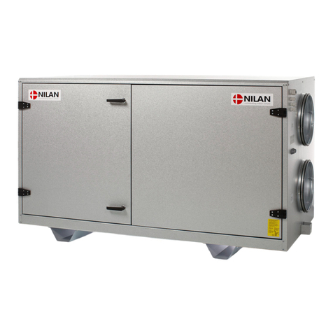
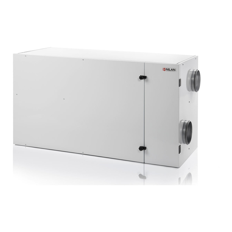
nilan comfort CT150 User manual

INSTALLATION INSTRUCTIONS
CTS602 LIGHT BY NILAN
Comfort CT150 / CT200 (English)
Version 3.00 - 27.09.2018

TABLE OF CONTENTS
Safety
Power supply .................................................................................................................................................................................................................................................................. 4
Disposal............................................................................................................................................................................................................................................................................................. 4
Ventilation system .................................................................................................................................................................................................................................................. 4
General information
Introduction.................................................................................................................................................................................................................................................................................. 5
General information prior to installation ........................................................................................................................................................................................5
Final inspection......................................................................................................................................................................................................................................................................... 6
Ventilation ........................................................................................................................................................................................................................................................................ 6
Unit type........................................................................................................................................................................................................................................................................................... 7
Product description ................................................................................................................................................................................................................................................ 7
Dimensional drawing ............................................................................................................................................................................................................................................. 8
Functional diagram .............................................................................................................................................................................................................................................. 10
Accessories................................................................................................................................................................................................................................................................................11
Electrical preheating element for frost protection.......................................................................................................................................................... 11
EM box ................................................................................................................................................................................................................................................................................ 11
Pollen filter ................................................................................................................................................................................................................................................................... 11
Water trap ......................................................................................................................................................................................................................................................................11
Flexible silencing...................................................................................................................................................................................................................................................... 12
Side mounted brackets for vertical mounting........................................................................................................................................................................12
Rear mounting brackets for vertical mounting.....................................................................................................................................................................12
Installation
Mounting.......................................................................................................................................................................................................................................................................................13
Positioning of the unit .......................................................................................................................................................................................................................................13
Installation rails........................................................................................................................................................................................................................................................ 14
Rear installation (accessories) ............................................................................................................................................................................................................... 14
Side installation (accessories) .................................................................................................................................................................................................................15
Electrical installation
Electrical connections....................................................................................................................................................................................................................................................16
Safety.................................................................................................................................................................................................................................................................................. 16
Connections list ....................................................................................................................................................................................................................................................... 16
Control panel............................................................................................................................................................................................................................................................................17
HMI Control panel................................................................................................................................................................................................................................................... 17
Wall bracket.................................................................................................................................................................................................................................................................. 18
Connecting the control panel.....................................................................................................................................................................................................................18
Electrical connections unit....................................................................................................................................................................................................................................... 19
Supply .................................................................................................................................................................................................................................................................................19
Unit ........................................................................................................................................................................................................................................................................................ 19
Electrical connections accessories................................................................................................................................................................................................................. 20
Connection to user selection and modbus .................................................................................................................................................................................20
External electrical preheating element ........................................................................................................................................................................................ 21
Plumbing installation
Condensate drain................................................................................................................................................................................................................................................................22
Important information .....................................................................................................................................................................................................................................22
Connections water trap ..................................................................................................................................................................................................................................23
Plumbing connections accessories..................................................................................................................................................................................................................24
Water lock with ball (option) ...................................................................................................................................................................................................................... 24
Ventilation mounting
Duct system.............................................................................................................................................................................................................................................................................. 25
Legislation...................................................................................................................................................................................................................................................................... 25
Ducts..................................................................................................................................................................................................................................................................................... 25
2

Unit..........................................................................................................................................................................................................................................................................................25
Extract air........................................................................................................................................................................................................................................................................26
Supply air......................................................................................................................................................................................................................................................................... 26
Roof stack....................................................................................................................................................................................................................................................................... 26
Balancing...................................................................................................................................................................................................................................................................................... 27
Important information .....................................................................................................................................................................................................................................27
Balancing connectors ........................................................................................................................................................................................................................................27
Pressure drop diagram..................................................................................................................................................................................................................................... 27
Comfort CT150 / CT200 (English) BY NILAN
3

Safety
Power supply
CAUTION
Always disconnect mains electricity to the unit if a fault occurs which cannot be rectified via the
control panel.
CAUTION
If a fault occurs on the electricity-conducting elements of the unit, always contact an
authorised electrical installer to rectify the fault.
CAUTION
Always disconnect mains electricity to the unit before opening the doors, e.g. for installation,
inspection, cleaning and filter change.
Disposal
Ventilation system
Nilan units mainly consist of recyclable materials. They should therefore not be
disposed of with household refuse. Take them to your local recycling centre.
4

General information
Introduction
General information prior to installation
The following documents are supplied with the unit:
• Installation instructions
• Software instructions
• User manual
• Wiring diagram
The instructions can be downloaded from the Nilan website: http://www.nilan.dk/en-gb/frontpage/
download
If you have further questions on unit installation after reading the instructions, contact your nearest
Nilan distributor, who can be found on www.nilan.dk/en-gb/frontpage/download/dealers.
The purpose of these instructions is to give the installer advice on correct installation and maintenance
of the unit.
ATTENTION
The unit must be started up immediately after installation and connection to the duct system. In
periods where the ventilation system is not in operation, humid air from the rooms may
penetrate into the ducts and form a condensate. The condensate may leak out of the valves and
damage furniture and floors. In addition, condensate may form inside the unit, damaging the
unit's electronics and fans.
The unit is supplied fully tested and ready for operation.
Comfort CT150 / CT200 (English) BY NILAN
5

Final inspection
Ventilation
How to set the unit
This list is for helping the installer get an overview of the settings, which have to be made in
consultation with the user or builder.
Function Settings
Setting for filter change period Days:
What level is set for basic ventilation Level:
Is low ventilation required in case of low outdoor temperature Yes/No Level:
At °C:
Is low ventilation required in case of low air humidity Yes/No Level:
Level low air humidity %
Is high ventilation required in case of high air humidity Yes/No Level:
Set maximum time for high air humidity Min:
What is the desired room temperature °C:
Is stop required at low room temperature Yes/No °C:
Is a cooker hood connected to the ventilation system Yes/No Level:
Is the pre-heating element to be activated (Polar version) Yes/No
6

Unit type
Product description
Comfort CT150 / CT200 is a ventilation unit with heat recovery. It is useable for air volumes up to 175 /
200 m 3 /h at 100 Pa external duct pressure.
The unit extracts humid and poor quality air from the home via the bathroom, toilet, kitchen and utility
room, and blows fresh air into rooms such as the lounge, bedrooms and office. Cold outdoor air is
heated in the heat exchanger by the warm extracted air.
Comfort CT150 / CT200 comes as standard with a plate filter for outdoor air and extract air. If you
want to filter pollen from outdoor air, a pollen filter is available for retrofitting.
The unit Front open Rear open
1. Duct connections 5. Extract air filter 9. Bypass damper
2. Filter change door 6. Outdoor air filter 10. Automation
3. Regulation nozzle (Pollen filter is fitted here) 11. Supply air fan
4. Electrical connection 7. Counterflow heat exchanger 12. Extract air fan
8. Condensate drain
Comfort CT150 / CT200 (English) BY NILAN
7

Dimensional drawing
All dimensions are in mm.
Left version:
27
27
20
1000
338
1040
5
1.
2. 4.
3.
526
326
93
94
224
535
91
326
94
174,8
Ø 125
333
5
Connections:
1. Outdoor air
2. Supply air
3. Extract air
4. Discharge air
5. Condensate drain
8

Right version:
1040
338
1000
5
1.
4.
3.
2.
203
95
90,1
325
526
535
5
333
Ø 125
92
325
95
137
27
27
Ø20
Connections:
1. Outdoor air
2. Supply air
3. Extract air
4. Discharge air
5. Condensate drain
Comfort CT150 / CT200 (English) BY NILAN
9

Functional diagram
3
2
5
1
6
4
TC
T8 T3
T4 T2 T9 T7
Connections Automation
1. Outdoor air T2/T7: Supply air sensor
2. Supply air T9: After-heating element frost protection
3. Extract air T3: Extract air sensor
4. Discharge air T4: Discharge and de-icing sensor
5. Condensate drain T8: Outdoor air sensor
6. Electrical and water after-heating element
connections
10

Accessories
Electrical preheating element for frost protection
In longer periods of sub-zero temperatures, the high-efficiency counterflow heat
exchanger will ice up. To avoid icing, it is recommended that an electrical
preheating element is mounted.
The preheating element uses very little energy, but ensures efficient heat
recovery without de-icing, thus achieving an overall saving in energy
consumption.
EM box
With an EM box it is possible to divide the extract air between the kitchen and
bathroom.
If the cooker hood is operating via the unit and is switched on, air extraction from
the bathroom reduces slightly to allow sufficient air for the cooker hood to
extract kitchen fumes.
The EM box has a metal filter which efficiently separates grease particles from
the cooker hood air, thus protecting the unit.
Pollen filter
The unit is supplied as standard with a plate filter.
If persons in the dwelling suffer from a pollen allergy, there is an option for
mounting a pollen filter in the outdoor air inlet to minimise the pollen in the
indoor air.
A pollen filter also removes approx. 50% of the hazardous particles in the
outdoor air, so if you live in a big city or near a freeway, a pollen filter is
recommendable.
Water trap
To ensure that the condensate can drain off freely, a water trap must be
established.
The water trap must be regularly checked for water. During the summer season,
where no condensation will occur, there is a risk of the water trap drying out. If
the water trap has dried out, air will be drawn into the unit and the condensate
cannot be drained, which will cause water damage.
The Nilan water trap contains a ball which cease to prevent "false" air intake into
the unit, so that condensate can run freely out of the unit.
Comfort CT150 / CT200 (English) BY NILAN
11

Flexible silencing
To facilitate later servicing of the unit, we recommend fitting a flexible
connection between the unit and the duct system.
Nilan's sound damping flexi-hose gives good sound damping both to the duct
system and to roof stacks.
Side mounted brackets for vertical mounting
For vertical mounting of the unit a wall bracket can be purchased and attached in
which the ducts can also be led and concealed. By vertical mounting the unit
works as a top-unit.
The side panels are prepared for mounting of the display panel.
Rear mounting brackets for vertical mounting
A wall bracket can be purchased and attached for mounting on the back of the
unit. By vertical mounting the unit works as a top-unit.
12

Installation
Mounting
Positioning of the unit
ATTENTION
When mounting the unit, consideration must always be given to future servicing and
maintenance.
It must be easy to replace filters, and it must be possible to perform tasks such as removing the heat
exchanger, replacing fans and other components.
ATTENTION
A minimum free space in front of the unit of 60 cm is recommended.
Comfort CT150 is a flexible unit which can be mounted horizontally, vertically or at an angle. However,
it is important that the exhaust is always positioned at the bottom (see illustration below).
ATTENTION
The system must be mounted in a level position. If this is not possible, there must be a decline
towards the condense water outlet.
Errors in the installation can cause moisture and water damages.
Systems that are not mounted on a walls or ceiling, MUST be mounted on a level and firm
surface.
Left version Right version
Comfort CT150 / CT200 (English) BY NILAN
13

Installation rails
Comfort CT150 is always supplied with a set of installation rails.
The rails must be mounted with a space between them of 1045 mm. The unit is then slid between them
and fixed by turning up the ends of the rails.
This is a simple and quick way of mounting the unit without having to hold it while screwing it into
position.
1045 mm
Rear installation (accessories)
It is possible to buy a mounting bracket, for mounting on the back on the unit.
It is a good solution, if the unit has to be installed vertically in a cabinet or a technical room. In this way,
the unit is converted to a "Top unit".
Installation front view Installation seen from above
Wall
14

Side installation (accessories)
It is possible to buy a mounting bracket, for mounting on the side of the unit.
Comfort CT150 is prepared that the side bracket can be mounted on either the right or the left side.
The ducts can be lead behind the bracket, which provides a nice installation.
It is possible to mount the control panel on the side bracket in the prepared holes.
The side brackets are mounted on the wall and the unit is then hung up on the bracket.
Comfort CT150 / CT200 (English) BY NILAN
15

Electrical installation
Electrical connections
Safety
ATTENTION
All work must be carried out by qualified personnel and in accordance with applicable legislation
and regulations.
ATTENTION
It is important that power is disconnected when working with the unit's electrical components.
It is important to check that cables have not been damaged or pinched during connection and use.
Connections list
All electrical connections are made on the right-hand side of the unit, viewed from the front, if mounted
horizontally.
If mounted vertically, the electrical connections are made at the bottom of the unit.
1. Connection of 230V supply (remember electrical grounding)
2. Connection of control panel
3. Connection of PC via a USB AB cable
1
2
3
16

Control panel
HMI Control panel
The control panel comes with 1½m of cable. The panel is connected to the CTS602 control system in
the unit with a CAT.5e cable (max. length 50 m).
ATTENTION
If a longer cable is wanted, use an ordinary LAN-cable not crossover cable, max. 50m.
If it is wished to extend the cable, please note the following:
Installation in the RJ12 plug
1. Empty
2. Empty
3. Green (A2)
4. Green/white (B2)
5. Brown (12V)
6. Brown/white (GND)
Use RJ12 plug and RJ12 crimping tool.
Installation in the 8 pole plug
1. Brown/white (GND)
2. Empty (B2)
3. Empty (A2)
4. Empty (User)
5. Empty (User)
6. Green/white (A1)
7. Green (B1)
8. Brown (12V)
Comfort CT150 / CT200 (English) BY NILAN
17

Wall bracket
The HMI panel is mounted on the wall using the integral wall bracket.
The panel should be placed visibly so it is possible to make changes to the settings and monitor
warnings or operation alarms.
The wall bracket is located on the back
of the panel and can be detached by
loosening the bracket at the bottom of
the panel so it can be removed.
The wall bracket is mounted to the wall
with 2 screws.
The RJ12 plug is clicked into the bottom
of the HMI panel and the wire can then
be guided down along the wall, into the
wall or into the groove in the back of the
panel.
Connecting the control panel
18

Electrical connections unit
Supply
CAUTION
Power sypply including safety switch must be installed by a certified electrician.
It comes with a power cable for connection in socket. It is important for the unit to be bonded to
earth.
The unit comes with a EU Schuko plug for 230V power supply. This means that you do not have
the protection of electrical grounding. The electrical grounding can be secured by connecting
the plug to an electrical outlet equipped with a ground pin.
It is also possible to connect the Schuko plug to a ground plug adapter with ground pin. This
Schuko adapter can be mounted on the unit, so that the unit is secured ground connection to
the Danish earth system.
Unit
Power supply 230V 50Hz max. 13A
Safety switch
Comfort CT150 / CT200 (English) BY NILAN
19

Electrical connections accessories
Connection to user selection and modbus
User selection: Connection to the user selection can e.g. be used for controlling the cooker hood
operation via a potential-free contact in the cooker hood, which provides the unit with a signal that
increases the ventilation when the damper is in use. Connection is made in pins 4 and 5 in the control
panel's 8 pole plug.
The user selection can also be used for other functions, e.g. to create imbalance in supply air and
extract air ventilation.
Modbus : It is possible to communicate with the unit via modbus, which can be connected in pins 1
(GND), 6 (A1) and 7 (B1) in the control panel's 8 pole plug.
Please refer to the user manual for software setup etc..
The plug is connected to the unit - see point 2: Connection of control panel under Connections list.
CTS/Computer
Converter
Modbus
Unit
Unit
Control panel
Control panel
20
Other manuals for comfort CT150
6
This manual suits for next models
1
Table of contents
Other nilan Heating System manuals
Popular Heating System manuals by other brands

Hotstart
Hotstart OXM Installation & operation manual

Innova
Innova EF40 Series Installation, instruction and service manual

Caladair
Caladair EVERSKY 500 Installation and commissioning manual

Aqua-Hot
Aqua-Hot 400-P02 Use and care guide

Monitor
Monitor 422 Service manual

Viessmann
Viessmann VITODENS operating instructions