Helios H-45L Guide

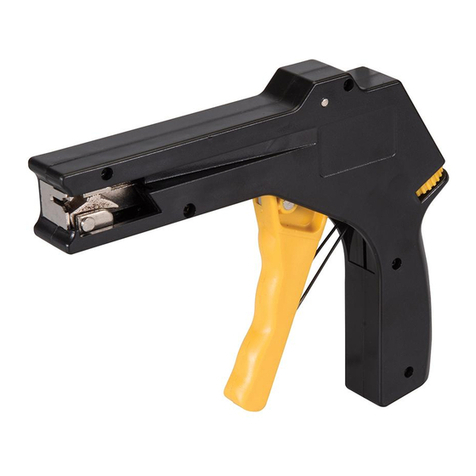
HELIOS H-45L
BATTERY-POWERED MANUAL TOOL
FOR PLASTIC STRAPPING
OPERATION MANUAL
&
SPARE PARTS LIST
Original Instruction
READ ALL INSTRUCTIONS BEFORE OPERATING THIS PRODUCT

PART I
CONTENTS
1. General Safety Rules .........................................................................1
2. Functional Unit .................................................................................3
3. Technical Data ..................................................................................4
4. Operation Elements ...........................................................................4
5. Operation ...........................................................................................5
6. Maintenance ......................................................................................9
7. Troubleshooting ................................................................................10
8. Wiring Diagram ................................................................................11

1. General Safety Rules
Warning:
DO NOT attempt to operate the tool until you have read and understood all instructions and
safety rules contained in this manual. Failure to comply may result in accidents involving
fire, electric shock, or serious personal injury. Save this owner’s manual for future
reference and review it frequently for safe operation.
Work Area
a. Keep work area clean and well lit. Cluttered and dark areas invite accidents.
b. Do not operate Power tools in explosive atmospheres, such as in the presence of
flammable liquids, gases or dust. Power tools create sparks which may ignite the dust
or fumes.
c. Keep bystanders, children and visitors away while operating a tool. Distractions can
cause you to lose control.
Electrical Safety
a. Charger’s plugs must match the outlet. Never modify the plug in any way. Do not
use any adapter plugs with earthed (grounded) power tools. Unmodified plugs and
matching outlets will reduce risk of electric shock.
b. Avoid body contact with earthed or grounded surfaces such as pipes, radiators,
ranges and refrigerators. There is an increased risk of electric shock if your body is
earthed or grounded.
c. Do not expose power tools to rain or wet conditions. Water entering a power tool will
increase the risk of electric shock.
d. Do not abuse the cord of charger. Never use the cord for carrying, pulling or
unplugging the power tool. Keep cord away from heat, oil, sharp edges or moving
parts. Damaged or entangled cords increase the risk of electric shock.
e. When operating a power tool outdoors, use an extension cord suitable for outdoor
use. Use of a cord suitable for outdoor use reduces the risk of electric shock.
Personal Safety
a. Stay alert, watch what you are doing and use common sense when operating a tool.
Do not use a tool while you are tired or under the influence of drugs, alcohol or
medication. A moment of inattention while operating power tools may result in serious
personal injury.
b. Use personal protective equipment. Always wear eye protection. Protective
equipment such as dust mask, non-skid safety shoes, hard hat, or hearing protection used
for appropriate conditions will reduce personal injuries.
c. Avoid accidental starting. Ensure the switch is in the off-position before insert
Battery. Carrying tools with your finger with the switch on invites accidents.
d. Remove any adjusting key or wrench before operation the tool. A wrench or a key
left attached to a rotating part of the tool may result in personal injury.
- 1 -
e. Do not overreach. Keep proper footing and balance at all times. This enables

- 2 -
f. Dress properly. Do not wear loose clothing or jewellery. Keep your hair, clothing
and gloves away from moving parts. Loose clothes, jewellery or long hair can be
caught in moving parts.
Power Tool Use and Care
a. Do not use the tool if the switch does not turn it on and off. Any tool that cannot be
controlled with the switch is dangerous and must be repaired.
b. Take off the battery pack from the tool before making any adjustments, changing
accessories, or storing tools. Such preventive safety measures reduce the risk of starting
the tool accidentally.
c. Store idle tools out of the reach of children and do not allow persons unfamiliar with
the tool or these instructions to operate the tool. Tools are dangerous in the hands of
untrained users.
d. Maintain tools. Check for misalignment or binding of moving parts, breakage of
parts and any other condition that may affect the tool’s operation. If damaged,
have the tool repaired before use. Many accidents are caused by poorly maintained
tools.
e. Use the tool, accessories and tool bits etc. In accordance with these instructions,
taking into account the working conditions and the work to be performed. Use of
the tool for operations different from those intended could result in a hazardous situation.
Battery Use and Care
a. Ensure the switch is in the off position before inserting the battery pack. Inserting the
battery pack into power tools that have the switch on invites accidents.
b. Recharge only with the charger specified by the manufacturer. A charger that is suitable
for one type of battery pack may create a risk of fire when used with another battery pack.
c. Use power tools only with specifically designated battery packs. Use of any other battery
packs may create a risk of injury and fire.
d. When the battery pack is not in use, keep it away from other metal objects like paper clips,
coins, keys, nails, screws, or other small metal objects that can make a connection from
one terminal to another. Shorting the battery terminals together may cause burns or a
fire.
e. Under abusive conditions, liquid may be ejected from the battery; avoid contact. If
contact accidentally occurs, flush with water. If liquid contacts eyes, additionally seek
medical help. Liquid ejected from the battery may cause irritation or burns.
Service
a. Have your power tool serviced by a qualified trained person using only identical
replacement parts. This will ensure that the safety of the power tool is maintained.
b. Tool service must be performed only by qualified trained personnel. Service or
maintenance performed by unqualified personnel may result in a risk of injury.
c. When servicing a tool, use only identical replacement parts. Follow instructions in the
Maintenance section of this manual. Use of unauthorized parts or failure to follow
Maintenance Instructions may create a risk of shock or injury.

2. Functional Unit
- 3 -
6 Battery Unit
H45-60002
3 Linkage Unit
H45-30000
2 Gripper Unit
H45-20000
4 Sealing & Cutting Unit
H45-40000
1 Tensioning Unit
5 Body Frame Unit
H45-50000
H45-10000

3. Technical Data
Battery Type remarks BOSCH Li-Ion , 14.4VDC , 2.6Ah
Charging Time About 30 minutes
(after 20 minutes, approx. 70% charge capacity)
Strapping Speed 3 sec/cycle (Auto)
Strap Width 9mm, 12mm, 16mm
Strap Type PET, PP
Strap Thickness PET : 0.5mm-1.05mm PP : 0.55mm~1.05mm
Sealing Joint friction weld
Vibration 7.77m/s^2
Noise emission sound pressure level: 83.8dB(A)
sound power level: 94.8dB(A)
Tension (max) 220 kg (485 lbs)
Dimensions
(L)×(W)×(H) 350mm × 157mm × 160mm
Weight 4.26 kg (9.4 lbs)
Working Temperature
The ambient temperature should be between -5℃and 45℃
( 23 ℉and 113℉)
The best performance is achieved between 15℃and 20℃
(59℉and 68℉)
Remarks:
If the tool will be idle for a long time, be sure to take out the battery to avoid reducing the
battery's life span.
4. Operating Elements
- 4 -
LED
Red Charge the battery
Yellow Cooling time is running
Green Strapping finish
Sealing switch (Semi)
Battery
Tension switch (Auto)
LED
LED Flash
Green Over Current
Green/Red Over Heat
Handle lever

5. Operation
(1) Installation
Inserting the Battery
Insert the battery from the top downward to the bottom into the battery slot of the tool until
hear the “click” sound. (refer to Fig. a) When the LED lights on GREEN shortly, the
battery is installed correctly.
(Fig.a)
Removing the Empty Battery
If the LED lights on RED while tensioning or welding, that means the battery is exhausted.
Please push the unlatching buttons (red color) on the top of the battery to take off the
battery.
Warning!
The last welding on the package might not have sufficient seal efficiency
and you would need to do it again after recharging the battery.
- 5 -

(2) Adjusting the Welding Pressure
In order to assure optimal welding, the pressure of the welding gripper to the straps to be
welded must be within a certain range. Depending on the thickness of the strap, this
pressure is adjusted by means of the adjusting the quantity of shim(s). Please see the
following chart.
When adjusting the welding pressure, the shim must be inserted
into "steel insert".
Disregarding this regulation will cause considerable trouble.
smooth strap embossed strap
strap thickness quantity for shim(s)
H45-40270 quantity for shim(s)
H45-40270
H45-40260
Steel Insert
H45-40270 0.5-0.6 mm 2 3
0.7-0.8 mm 1 2
0.9-1.05 mm 0 1
Shim
(3) Adjustments
(a) Preselecting of Strap Tension and Tensioning Speed
Do not adjust the tensioning force too high. If
the tensioning force is higher than the strength of
the strap, the strap will tear while tensioning.
Tensioningforcecanbepreselectedwith
the left adjusting knob. Turning it clockwise
increases the tensioning force, while turning it
counterclockwise decreases the tensioning force.
Adjusting knob for tensioning force
Adjusting knob for sealing time
Protection
cover
- 6 -
When P.P. straps or straps with thinner thickness around 0.55mm to 0.7mm are still
being damaged by H45-10090 (tension wheel) during strapping while the tension is at
the lowest level (make a counterclockwise turn on the tension knob to the end), simply
use an allen key wrench to make a counterclockwise turn on the trimmer of P.C. Board.
You need to take off the protection cover first and you will then see the VR underneath
the protection cover. After making all the adjustments, tension will become lower.
When the tension becomes as low as you desired, just put the protection cover back.
On the other hand, if tension is not enough while it is at the highest level (make a
clockwise turn on the tension knob to the end), simple make a clockwise turn on the
trimmer of P.C. Board for even higher tension.

(b) Adjusting the Sealing Time
Depending on the size and quality of the strap, different welding times are required.
Turning the knob clockwise increases the welding time, while turning it
counterclockwise decreases the welding time.
(4) Feeding the Strap Around the Package
The strapping is fed around the package as illustrated.
- 7 -
Warning! The plastic strap which will be welded
must be free from oil, grease and other dirt.
Dirty plastic straps can't be welded correct!
(5) Inserting the Strap
Pull up the handle lever firmly with your right hand.
Insert the two straps well aligned on each other into
the strap guide using your left hand.
Release the handle lever.
(6) Tensioning and Sealing the Straps
-Auto
Press down the rocker switch until the desired strap
tension is reached.The tool will do sealing by itself.
Release the rocker switch when it’s finished.
-Semi
Press down the rocker switch and then release it, and
press down again and again till the desired tension is
reached.
-Sealing the Straps
Press the black switch to sealing the straps.
The plastic strap is welded and cut off from the strap coil at the same time.
During welding, the LED lights green.
After expiration of the adjusted welding time, the cooling down time begins (LED lights
yellow).
When the LED lights green again, the sealing procedure is finished.

- 8 -
(7) Removing the Tool
Pullupthehandlelever,pullthetoolright/backwards
and off the strapping.
(8) Seal - Control
Aregularcontrolofthesealisnecessary.Thesealcan
be examined visually.
Make a seal, peel it apart and examine it as follows:
Correct Seal
Thesealmustbecompletelyweldedoverthewhole
width of the strap on a length.
Minor quantities of fused plastic may overflow on sides.
Welding Time Too Short
Theplasticstrapisnotweldedoverthewholewidthof
the strap.
The seal efficiency is insufficient.
Warning! Straps with insufficient seal strength must be
removed from the package!
Adjust the welding time.
Welding Time Too Long
If the welding time is too long the straps are
overheated.
The fused plastic overflows on both sides of the straps.
The seal efficiency is affected.
Warning! Straps with insufficient seal strength must be
removed from the package!
Adjust the welding time.

6. Maintenance
Please take off the battery before doing maintenance.
(1) Use air gun to clean the area around Tensioning Wheel (H45-10090) and Gripper
(H45-10070/H45-10071) and the area around Cutter (H45-40090) daily. Be sure to use the
air gun by blowing the debris from the left side to avoid any debris blowing to inside of the
tool.
Air blow
Air blow
H45-10070/10071
H45-10090 H45-40090
(2) If air gun could not dislodge the debris between the teeth of Tensioning Wheel (H45-10090),
PET (or other plastic) is suggested to dislodge the debris by sharing the tip.
Please do not use any metal material or hard material to clean the teeth to avoid any damage
to the teeth.
H45-10090
PET strap
- 9 -

(3) DISPOSAL
The power tool, accessories and packaging materials should be sorted for
environmental-friendly recycling.
Do not dispose of power tools into household waste!
According the European Guideline 2002/96/EC for Waste Electrical and
Electronic Equipment and its implementation into national right, power tools
that are no longer usable must be collected separately and disposed of in an
environmentally correct manner.
7. Troubleshooting
(1) The strap slips while tensioning
a. Tension force setting is higher than the Strap Strength. Please turn down the tension
(refer to Page no.6 in Part I of Manual).
b. There is too much strap debris on the teeth of the Tensioning Wheel (H45-10090) or
Gripper (H45-10070)
c. Strap Stop (H45-10280/H45-10281) touches the straps. (shown as following
drawing). Please clean the Strap Stop (H45-10280) and feed the strap appropriately
until the Strap Stop won’t affect the strap while tension.
Strap Stop touches the straps
touch the strap
H45-10280/10281
d. The Tensioning Wheel (H45-10090) or the Gripper’s (H45-10070/ H45-10071) teeth is
worn and need replacement.
(2) The strap can not be cut completely
a. The sealing time might be set too short.
b. The strap is not thread correctly so a small part of the strap is not cut completely.
c. The Shim (H45-40270) are too many or insufficient.
- 10 -
d. The Cutter (H45-40090) is worn.

8. Wiring Diagram
- 11 -


1 TENSIONING UNIT H45-10001
H45-10002
REF.
NO. PART NO. DESCRIPTION Q'TY REMARKS
H45-10001 Tensioning Unit (For 12mm) 1
H45-10002 Tensioning Unit (For 16mm) 1
H45-10003 Tensioning Unit (For 9mm) 1
1 H45-10010 End Cover 1
2 H45-10020 Torsion Spring 1
3 H45-10030 Strap Stop (For 16mm) 1
H45-10031 Strap Stop (For 9mm/12mm) 1
4 H45-10040 Tensioning Body 1
5 H45-10050 Swivel Shaft 1
6 H45-10060 Holder 1
7 H45-10070 Gripper (For 16mm) 1
H45-10071 Gripper (For 9mm/12mm) 1
8 H45-10080 Holder (For 16mm) 1
H45-10081 Holder (For 9mm/12mm) 1
9 H45-10090 Tensioning Wheel 1
10 H45-10100 Dowel 3
11 H45-10110 Parallel Pin 3
12 H45-10120 Idler Gear 3
13 H45-10130 Washer 1
14 H45-10140 Tensioning Wheel Shaft 1
15 H45-10150 Parallel Pin 3
16 H45-10160 Idler Gear 3
17 H45-10170 Cover 1
18 H45-10180 Bearing 1
19 H45-10190 Tension Gear 1
20 H45-10200 Spur Wheel 1
21 H45-10210 M1 Motor Support 1
24 H45-10240 Screw 1
25 H45-10250 Washer 2
26 H45-10260 Tube 1
27 H45-10270 Set Ball 1
28 H45-10280 Strap Stop (For 12mm/16mm) 1
H45-10281 Strap Stop (For 9mm) 1
29 H45-10290 M1 Motor Ass'y 1
- 2 -

1 TENSIONING UNIT H45-10001
H45-10002
REF.
NO. PART NO. DESCRIPTION Q'TY REMARKS
30 H45-10300 Cover 1
31 BK0808Z Needle Bearing, 0808Z 1
32 BR6806 Bearing, 6806 1
33 BR6806Z Bearing, 6806Z 2
34 BR6808Z Bearing, 6808Z 1
35 FHS0410N FHS, M4×10 (N) 3
36 FHS0514N FHS, M5×14 (N) 3
37 FHS0308N FHS, M3×8 (N) 2
38 HBS0410N HBS, M4×10 (N) 2
39 HBS0430HN HBS, M4×30 (H)(N) 2
40 HBS0516N HBS, M5×16 (N) 1
41 HN05 HN, M5 1
42 KT-477N Needle Bearing, 477N 3
43 KT-5810N Needle Bearing, 5810N 3
44 HBS0412N HBS, M4×12 (N) 2
45 SB04 Ball, Ø4 1
46 MB0815 Metal Bushing, 0815 2
47 FHS0306N FHS, M3×6 (N) 2
48 SP0306 Spring Pin, 3×6 5
49 SP0432 Spring Pin, 4×32 1
51 SW04 SW, M4 6
52 SW05 SW, M5 2
60 H45-10600 Tensioning Wheel Shaft Ass'y 1
61 H45-10700 Tensioning Body Ass'y (For 16mm) 1
H45-10701 Tensioning Body Ass'y (For
9mm/12mm) 1
-3-


2 GRIPPER UNIT H45-20000
REF.
NO. PART NO. DESCRIPTION Q'TY REMARKS
3 H45-20030 Spring 2
4 H45-20040 Eccentric Shaft 1
5 H45-20050 Inner Raceway 1
6 H45-20060 M2 Motor Gear 1
7H45-20070 Switch Rocker 1
8 H45-20080 M2 Motor 1
10 H45-20100 Eccentric Shaft Gear 1
11 H45-10250 Washer 1
12 H45-20120 M2 Motor Ass'y 1
13 H45-20110 Spring Slide Ass'y 1
18 LA-50210 Label 1
23 HBS0320N HBS, M3×20 (N) 1
24 HN05 HN, M5 1
25 HSS0305 HSS, M3×5 4
26 MB0805 Metal Bushing, 0805 1
27 MB1709 Metal Bushing, 1709 1
28 PMS0218 PMS, M2×18 2
29 PW05B PW, M5 (B) Ø13 1
30 SP0310 Spring Pin, 3×10 1
32 SW02 SW, M2 2
33 SW03 SW, M3 1
35 SW05 SW, M5 1
-5-

Table of contents


