Beta INSTRUCTIONS
AIR RIVETER
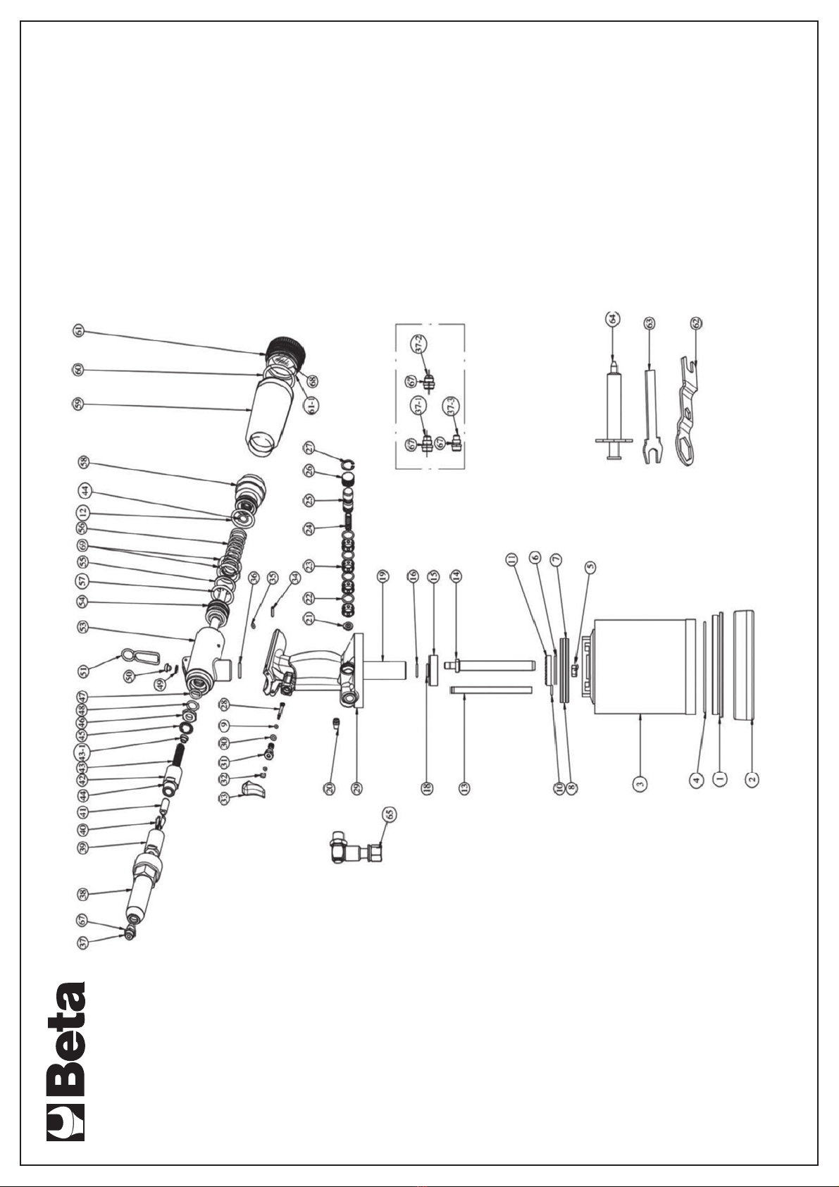
item 1946C 7,8
INSTRUCTION MANUAL FOR AIR RIVETERS
Tool distributed by:
BETA UTENSILI SPA
TO BE ABSOLUTELY DELIVERED TO THE
USER
To reduce the risk of any, damage to people, before using
or repairing the tool, doing any maintenance jobs or
replacing any accessories,
READ ALL THE SECTIONS OF THE INSTRUCTION
MANUAL CAREFULLY.
SAFETY INSTRUCTIONS FOR AIR RIVETERS
It is our aim to supply air tools which allow you to work
efficiently and SAFELY.
It is however understood that YOU are the most important
‘safety device’ for any tool, as taking meticulous care is the
best way of preventing injury.
Although we cannot enumerate all types of risks here, we tried
to lay stress on some of the most significant ones.
Let us remind you that this tool must be used only by skilled
workers and that the machine must never be forced; do not
overload the tool.
RISKS DUE TO CONNECTION TO COMPRESSED AIR
Compressed air may harm people severely.
Do not direct air towards you or any other people.
The air coming out of the hoses may harm people severely;
periodically check whether the hoses and/or fittings are loose
and/or have been damaged.
Whipping hoses may cause severe damage.
Before handling the tool, close the main plant, release residual
pressure and disconnect the tool only when it is not working.
Pressure must not exceed 6.2 bar, as measured at the air inlet
while the tool is working, or the value shown on the tool plate.
RISKS OF VARIOUS KINDS
Stay at a safety distance from the rotating parts of the tool.
Do not wear any accessory round your neck, such as chains or
necklaces. Do not wear any bracelets or loose clothes.
Avoid contact of accessories and tools with your hair.
Avoid contact with any accessories in motion, while the tool is
being used or after it has been used.
Always wear work gloves to reduce the risk of cutting and
burning yourself.
RISKS DUE TO SPLINTERS AND FRAGMENTS
Warning: small splinters and fragments may also harm your
eyes and result in blindness.
Always wear eye protection while using the tool, doing any
maintenance jobs and replacing any accessories or spare
parts. This measure must also be taken by anyone who
works nearby.
RISKS RELATED TO WORKING CONDITIONS
Mind too long hoses left at the work station; stumbling and
falling is likely to result in severe injury.
High noise levels may result in permanent loss of hearing;
wear ear protection, as recommended by the employer
and/or the regulations.
Stay in a safe, well-balanced position.
Repetitive movements and awkward positions combined with
vibrations may cause your hands and arms to be harmed;
special precautions should be taken.
Do not breathe dust and waste; partially protect yourself
with a filtering mask.
Both the workers and the maintainers must be physically fit for
the size, weight and power of this tool.
This tool was not designed to be used in areas exposed to the
risk of explosion and is not so insulated as to come into contact
with power sources.
OTHER SAFETY REQUIREMENTS
This tool and its parts and accessories must not be modified
and/or tampered with.
The building material of this tool may be subject to wear.
Working with compressed air tools may result in high
vibrations; therefore, take any precautions needed.
Prevent your hands from being trapped between the tool and
any object.
FOR FURTHER INFORMATION ABOUT SAFETY REFER TO
THE FOLLOWING:
The documents, information and instructions supplied with this
tool;
The employer, trade associations and/or trade unions;
The EEC Council and/or local authorities
“Safety Requirements for Hand Held Non-Electric Tools”,
available at: European Committee for Standardization, Rue de
Stassart 36, 1050 Brussels, Belgium.
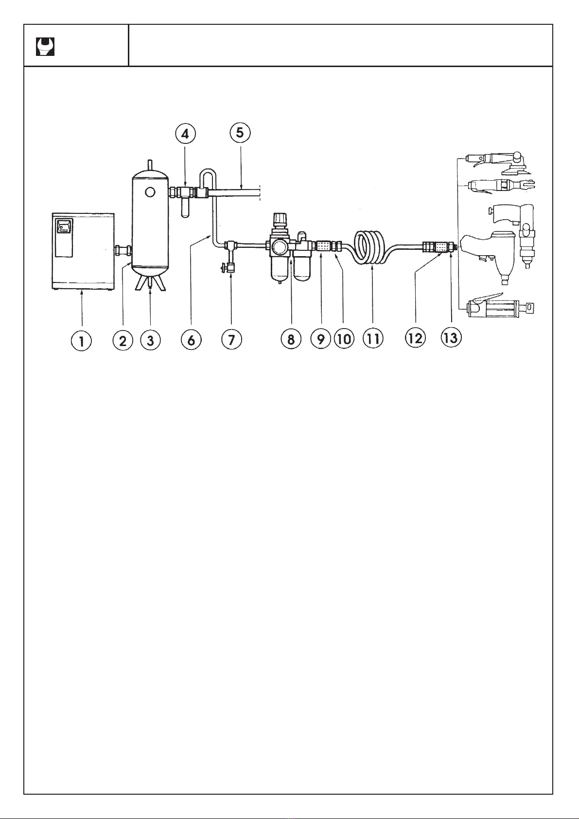
REQUIREMENTS FOR PROPER AIR CONNECTION
Feed the tool with clean air, free from water or condensate, at
a pressure of 6.0 bar, as measured at the air inlet, while the
tool is working.
An excessively high pressure results in a shorter life for the
mechanical parts and may cause people to be severely
harmed.
Connect the tool to the feeding plant, using accessories of the
same size as that shown in the enclosed drawing.
Do not fix any quick couplers directly into the air inlet.
Consult the instructions to connect the accessories properly.
Consult the specifications in this manual.