Renishaw NC4 User manual

#renishaw
NC4 non-contact tool setting separate
system
www.renishaw.com/nc4
Installation guide

Compliance information for this product is available by scanning the QR code or visiting
www.renishaw.com/mtpdoc

i
www.renishaw.com/nc4
Contents
Before you begin ...................................................................1-1
Trade marks ........................................................................1-1
Warranty ...........................................................................1-1
CNC machines ......................................................................1-1
Care of the system ...................................................................1-1
Patents ............................................................................1-2
NC4 non-contact tool setting separate system software notices ................................1-2
US government notice ...........................................................1-2
Renishaw software EULA.........................................................1-2
Intended use........................................................................1-2
Safety .............................................................................1-3
Information to the user ...........................................................1-3
Information to the machine supplier / installer .........................................1-4
Information to the equipment installer ...............................................1-4
Equipment operation ............................................................1-4
Warnings ..........................................................................1-5
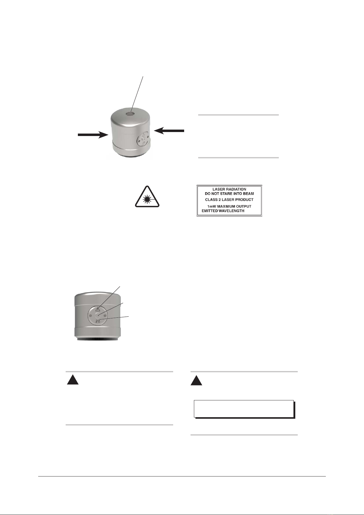
Laser safety and warning labels .........................................................1-6
Location of the laser aperture...........................................................1-6
NC4 basics ........................................................................2-1
Introduction.........................................................................2-1
NC4 unit components.................................................................2-1
Guidelines for best practice ............................................................2-2
NC4 specication ....................................................................2-3
NC4 specication (continued)...........................................................2-4
Dimensions of NC4 units ..............................................................2-5
System installation..................................................................3-1
How to install and congure the NC4 system...............................................3-1
Air supply information .................................................................3-2
Best practices .......................................................................3-2
Installing the air preparation pack........................................................3-3
Installing the NC4 system..............................................................3-4
Installing the NCi-6 interface unit ........................................................3-7
NC4 system wiring details .............................................................3-8
Supplying electrical power to the NCi-6 interface unit ........................................3-8
Power loss and restoration .............................................................3-8
Setting the NC4 barrier air pressure......................................................3-9

ii NC4 non-contact tool setting system
Macro programming software..........................................................3-10
Software and user information .........................................................3-10
Machine tool apps ..................................................................3-10
Head alignment of the NC4 unit ........................................................3-11
Aligning the NC4 unit to the machine axes................................................3-14
Alignment tolerances ................................................................3-15
Maintenance .......................................................................4-1
Introduction.........................................................................4-1
Removing and retting the air preparation lter elements .....................................4-2
Removal and replacement of membrane dryer module . . . . . . . . . . . . . . . . . . . . . . . . . . . . . . . . . . . . . . .4-3
Cleaning the optics...................................................................4-5
Cleaning the NC4 unit ...........................................................4-5
To clean the optics ..............................................................4-6
After cleaning the NC4 unit .......................................................4-7
Using a voltmeter ...............................................................4-8
NC4 set-up tool......................................................................4-9
Introduction....................................................................4-9
Dimensions....................................................................4-9
Using the set-up tool ...........................................................4-10
Replacing the set-up tool battery ..................................................4-11
Battery specication ............................................................4-11
Status LED function .................................................................4-12
Fault-nding .......................................................................5-1
Parts list ..........................................................................6-1
NC4 separates unit pack, supplied with:...................................................6-1
NC4 separates installation pack, supplied with: .............................................6-2

1-1
www.renishaw.com/nc4
Before you begin
Trade marks
Google Play and the Google Play logo are trademarks of Google LLC.
Apple and the Apple logo are trademarks of Apple Inc., registered in the U.S. and other countries. App
Store is a service mark of Apple Inc., registered in the U.S. and other countries.
Warranty
Unless you and Renishaw have agreed and signed a separate written agreement, the equipment and/or
software are sold subject to the Renishaw Standard Terms and Conditions supplied with such equipment
and/or software, or available on request from your local Renishaw ofce.
Renishaw warrants its equipment and software for a limited period (as set out in the Standard Terms
and Conditions), provided that they are installed and used exactly as dened in associated Renishaw
documentation. You should consult these Standard Terms and Conditions to nd out the full details of your
warranty.
Equipment and/or software purchased by you from a third-party supplier is subject to separate terms and
conditions supplied with such equipment and/or software. You should contact your third-party supplier for
details.
CNC machines
CNC machine tools must always be operated by fully-trained personnel in accordance with the
manufacturer’s instructions.
Care of the system
Keep system components clean and treat the unit as a precision tool.

1-2 NC4 non-contact tool setting system: Before you begin
Patents
Features of the NC4 non-contact tool setting separate system and features of similar Renishaw products,
are the subject of one or more of the following patents and/or patent applications:
NC4 non-contact tool setting separate system software
notices
This NC4 non-contact tool setting separate system includes embedded software (rmware) to which the
following notices apply:
US government notice
NOTICE TO UNITED STATES GOVERNMENT CONTRACT AND PRIME CONTRACT CUSTOMERS
This software is commercial computer software that has been developed by Renishaw exclusively at
private expense. Notwithstanding any other lease or licence agreement that may pertain to, or accompany
the delivery of, this computer software, the rights of the United States Government and/or its prime
contractors regarding its use, reproduction and disclosure are as set forth in the terms of the contract
or subcontract between Renishaw and the United States Government, civilian federal agency or prime
contractor respectively. Please consult the applicable contract or subcontract and the software licence
incorporated therein, if applicable, to determine your exact rights regarding use, reproduction and/or
disclosure.
Renishaw software EULA
Renishaw software is licensed in accordance with the Renishaw licence at:
www.renishaw.com/legal/softwareterms
Intended use
The NC4 is a laser-based non-contact tool setting system that provides high-speed/high-precision
measurement of cutting tools on a machining centre under normal operating conditions.
CN 100394139
EP 1502699
JP 4520240
US 7312433

1-3
www.renishaw.com/nc4
Safety
Information to the user
The NC4 set-up tool (Renishaw part no. A-4114-8000, sold separately) is supplied with non-rechargeable
lithium metal batteries. Refer to the battery manufacturer’s literature for specic battery operating, safety
and disposal guidelines.
• Do not attempt to recharge the batteries.
• Replace the batteries only with the specied type.
• Do not mix new and used batteries in the product.
• Do not mix different types or brands of batteries in the product.
• Ensure that all batteries are inserted with the correct polarity in accordance with the instructions in
this manual and indicated on the product.
• Do not store the batteries in direct sunlight.
• Do not expose the batteries to water.
• Do not expose the batteries to heat or dispose of the batteries in a re.
• Avoid forced discharge of the batteries.
• Do not short circuit the batteries.
• Do not disassemble, apply excessive pressure, pierce, deform or subject the batteries to impact.
• Do not swallow the batteries.
• Keep the batteries out of the reach of children.
• If the batteries are swollen or damaged do not use them in the product and exercise caution when
handling them.
• Dispose of waste batteries in accordance with your local environmental and safety laws.
Ensure that you comply with international and national battery transport regulations when transporting the
batteries or this product with the batteries inserted. Lithium metal batteries are classied as dangerous
goods for transportation and require labelling and packaging in accordance with the dangerous goods
regulations before being offered for transportation. To reduce the risk of shipment delays, should you need
to return this product to Renishaw for any reason, do not return any batteries.
In all applications involving the use of machine tools, eye protection is recommended.

1-4 NC4 non-contact tool setting system: Before you begin
Information to the machine supplier / installer
It is the machine supplier’s responsibility to ensure that the user is made aware of any hazards involved in
operation, including those mentioned in Renishaw product literature, and to ensure that adequate guards
and safety interlocks are provided.
If the NC4 unit fails, the output signal may falsely indicate beam not blocked. Do not rely on signals from
the NC4 unit to halt the movement of the machine.
Information to the equipment installer
All Renishaw equipment is designed to comply with the relevant UK, EU and FCC regulatory requirements.
It is the responsibility of the equipment installer to ensure that the following guidelines are adhered to, in
order for the product to function in accordance with these regulations:
• any interface unit MUST be installed in a position away from any potential sources of electrical noise
(for example, power transformers, servo drives);
• all 0 V/ground connections should be connected to the machine “star point” (the “star point” is a single
point return for all equipment ground and screen cables). This is very important and failure to adhere
to this can cause a potential difference between grounds;
• all screens must be connected as outlined in the user instructions;
• cables must not be routed alongside high current sources (for example, motor power supply cables),
or be near high-speed data lines;
• cable lengths should always be kept to a minimum.
Equipment operation
If this equipment is used in a manner not specied by the manufacturer, the protection provided by the
equipment may be impaired.

1-5
www.renishaw.com/nc4
Warnings
Use of controls or adjustments or performance of procedures other than those specied within this
publication may result in hazardous radiation exposure.
Switch off the power supply before carrying out maintenance on the NC4 system.
When using the NC4 system, basic safety precautions must always be followed to reduce the risk of re,
electric shock and personal injury, including the following:
• Read all instructions before operating this product.
• The device must only be installed and used by competent, trained personnel.
• Use eye protection to protect against mechanical hazards, coolant and swarf.
• Avoid inhalation of coolant vapour from the machine tool.
• Do not block the air exiting from the transmitter or receiver.
• Prevent direct exposure of the eyes to the laser beam.
• Ensure that the beam is not reected into the eyes via any reective surface.
CAUTION – LASER SAFETY
The laser used in the Renishaw NC4 non-contact tool setting system emits visible red light at a wavelength
of 670 nm and has a power output of less than 1 mW.
The NC4 is classied as a Class 2 laser product as dened by BS EN 60825-1:2014.
Complies with 21 CFR 1040.10 and 1040.11 except for conformance with IEC 60825-1 Ed. 3., as
described in Laser Notice No. 56, dated May 8, 2019.
BS EN 60825-1:2014 directs to attach a laser warning label and explanatory label.
A warning label and explanatory label are permanently xed to each side of the transmitter (Tx) housing
(see page 1-6, “Laser safety and warning labels”, for further information). An adhesive warning label is
also provided. Renishaw advise attaching this label to the outside of the machine tool, in a visible location.

1-6 NC4 non-contact tool setting system: Before you begin
激光辐射
请勿直视激光光束
Laser safety and warning labels
Label B
Label A
Laser ‘On’ and status LED (for more information, see
page 4-12, “Status LED function”).
NOTE: Labels A and B are tted to
the transmitter head only.
An adhesive warning label is
provided for attachment outside the
machine.
Label A Label B
Location of the laser aperture
Access panel identication markings, denoting system range (for
more information, see the NC4 non-contact tool setting system
accessories data sheet (Renishaw part no. H-2000-2223)).
Laser aperture / MicroHole™
Caution symbol (see “CAUTION symbol” below,
for further information)
CAUTION – LASER SAFETY
The access panel is to be removed for service
purposes only using the special tool supplied.
Before removing the panel, switch off electrical
power to the transmitter head to avoid exposure
to the laser beam.
CAUTION SYMBOL
The caution symbol on the access panel denotes
the following:
CAUTION – Class 3R Laser radiation when
open. Avoid direct eye exposure.
This text is not included on the access panel due
to the limited space available.
!!
Complies with 21 CFR 1040.10 and 1040.11
except for conformance with IEC 60825-1
Ed. 3., as described in Laser Notice No. 56,
dated May 8, 2019.
670nm

2-1
www.renishaw.com/nc4
NC4 basics
Introduction
This guide describes how to install, congure, maintain and service the Renishaw NC4 non-contact tool
setting system.
The NC4 is a laser-based non-contact tool setting system that provides high-speed/high-precision
measurement of cutting tools on a machining centre under normal operating conditions.
As a tool moves through the laser beam, the system detects when the beam is broken. Output signals sent
to the controller allow the presence of a tool and the position of the tip to be established. This can be used
to determine the dimensions of tools (tool measurement) or condition of tools (broken tool detection).
NC4 unit components
Rx head
Status LED
Access
panels
Status LED
Tx head
Access panel
Laser
aperture /
MicroHole™
Access panel
identication
marking
3-plate adjuster pack
Typical mounting
bracket

2-2 NC4 non-contact tool setting system: NC4 basics
Guidelines for best practice
• The NC4 unit is a precision device and must be handled with care.
• Ensure that all mountings are secure.
• Keep electrical contacts clean.
• Mount the NC4 unit in a position that limits the risk of it being subjected to impact when operating the
machine.
• Mount the NC4 unit in a position where it will not be affected by a build-up of swarf. Do not allow
excessive waste material to build up on or around the NC4 unit.
• Cables, piping and conduit should be suitably secured to avoid damage and loads being transferred to
the NC4 unit.
• Optimum performance is achieved by continuously supplying air and power to the NC4 unit.
• The NC4 unit is protected by a continuous stream of clean air. Approximately once a month, inspect
the optics for contamination. The service interval may be extended or reduced depending on
experience.
• The NC4 barrier air supply must conform to BS ISO 8573-1 air quality of Class 1.4.2 and be moisture-
free.

2-3
www.renishaw.com/nc4
NC4 specication
Principal
application
High-precision, high-speed non-contact tool setting and tool breakage detection on
all sizes of vertical and horizontal machining centres, multi-tasking machines and
gantry machining centres.
Transmission type Hard-wired transmission
Compatible
interfaces
NCi-6
Repeatability ±1.0 μm (39.37 μin) 2s at 1 m separation
Output signal
(from interface unit)
Two voltage-free, solid-state relays (SSR). Each can be either normally open or
normally closed (selectable via a switch). Current (maximum) 50 mA, voltage
(maximum) ±50 V.
The interface contains an auxiliary relay which can be used for switching the output
between the NC4 and a spindle probe. This relay can also be used to control an air
blast solenoid (optional).
Supply voltage
(to interface)
11 Vdc to 30 Vdc
Supply current
(to interface)
120 mA @ 12 Vdc, 70 mA @ 24 Vdc
Supply protection Resettable fuses in interface. Reset by removing power and cause of fault.
Electrical
connection
arrangement
Cable on the end of the units.
Other congurations are available on request.
Cable
(to interface)
Specication Ø6.0 mm (0.24 in), two twisted pairs, two individual cores plus
screen, each core 18 × 0.1 mm insulated.
Length 12.5 m (41.01 ft)
Electrical
connection
Cable on the end of the unit.
Other congurations are available on request.
Barrier air
pneumatic supply
Air supply to the NC4 must conform to BS ISO 8573-1 Class 1.4.2. 6.0 bar
(87.02 psi) maximum.
Air pipe: Ø3.0 mm (0.12 in) × 5.0 m (16.40 ft).
Laser type Class 2 laser product:
1 mW maximum output emitted wavelength 670 nm.
WARNING: Laser radiation. Do not stare into the beam.
Weight (including
12.5 m (41.01 ft) of
cable)
500 g (1.1 lb) for single transmitter or receiver unit and cable.

2-4 NC4 non-contact tool setting system: NC4 basics
Mounting Mounting achieved via a 3-plate or single plate adjuster pack (sold separately); see
the NC4 non-contact tool setting accessories data sheet (Renishaw part number
H-2000-2223).
Environment IP rating IPX6 and IPX8, BS EN 60529:1992+A2:2013
Storage
temperature
–25 °C to +70 °C (–13 °F to +158 °F)
Operating
temperature
+5 °C to +55 °C (+41 °F to +131 °F)
NC4 specication (continued)

2-5
www.renishaw.com/nc4
Dimensions of NC4 units
Ø30 (Ø1.18)
35 (1.38)
19 (0.75)
5.4 (0.21)
24 (0.95) A/F
7.5 (0.29)
AE
B
B
1.0 (0.039)
4.0 (0.16)
3.0 (0.12)
C
D
9.5 (0.37) 9.5 (0.37)
F
A
7.5 (0.29)
4.0 (0.16)
1.0 (0.039)
Ø26 (Ø1.02)
Dimensions given in mm (in)
A = Mounting holes (×2) M3 × 0.5 P × 8 (0.32) deep.
B = Dowel holes (×2) Ø2 × 8 (0.32) deep.
C = Pneumatic push-t connector Ø3 (Ø.12) plastic
pipe.
D = Supply cable, Ø6 mm (Ø.24).
E = PassiveSeal vent. Do not cover
F = Blanking screw. Do not disturb.
View from bottom of
transmitter and receiver

2-6 NC4 non-contact tool setting system: System installation
This page is intentionally left blank.

3-1
www.renishaw.com/nc4
System installation
How to install and congure the NC4 system
Install and congure the NC4 system in the sequence described below:
1. Install the air preparation pack (see page 3-3, “Installing the air preparation pack”, for further
information). Do not switch on the air supply or set the air pressure at this stage.
2. Install the NC4 system (see page 3-4, “Installing the NC4 system”, for further information).
3. Install the NCi-6 interface unit (see page 3-7, “Installing the NCi-6 interface unit”, for further
information).
4. Switch on electrical power to the NCi-6 interface unit (see page 3-8, “Supplying electrical power to
the NCi-6 interface unit”, for further information).
5. Switch on the barrier air supply to the NC4 unit and set the air pressure (see page 3-9, “Setting the
NC4 barrier air pressure”, for further information).
6. Align the NC4 unit (see page 3-14, “Aligning the NC4 unit to the machine axes”, for further
information).
7. Finally, calibrate the system as described in the appropriate non-contact tool setting software
programming guide.
8. If problems occur, or for more information, see page 5-1, “Fault-nding”.
Air preparation for barrier air
CNC machine
controller
Reduce pipe
diameter and split
as appropriate
Rx head
NCi-6 interface
unit
Ø3.0 mm
air pipe
Ø6.0 mm
air pipe
Ø6.0 mm (0.24 in) cable
Ø3.0 mm
air pipe
Tx head

3-2 NC4 non-contact tool setting system: System installation
Air supply information
The barrier air supply to the NC4 unit must conform to BS ISO 8573-1 air quality of Class 1.4.2 and be
moisture-free. If the air quality cannot be guaranteed, an air preparation pack is available from Renishaw;
see the NC4 non-contact tool setting accessories data sheet (Renishaw part no. H-2000-2223).
The NC4 unit requires a continuous regulated air supply of up to 0.6 MPa (87.02 psi) maximum.
Failure of the air supply causes a PassiveSeal™ inside each NC4 unit to activate, protecting the unit from
the ingress of contaminants. This causes the unit to enter a trigger state. The laser beam will not be seen
exiting the transmitter head.
The cause of the air failure should be determined and rectied.
Best practices
• Where possible, tap into the air supply that exits the machine air supply lter/regulator unit. Do not
connect the NC4 unit to an oiled air supply.
• When cutting air pipe, ensure it is cut straight, as a tapered cut could compromise sealing.
• Use blanking caps, supplied with the air preparation pack, when feeding air pipe through the conduit/
machine.
• Before connecting the air pipes to the inlet of the NC4 unit, briey switch on the air supply to clear out
any debris from the pipe. When no more debris is emitted, switch off the air supply and connect to the
NC4 unit.
• When installing the air pipes to the NC4 unit, keep runs as short as possible to minimise pressure
drop.
• If the temperature of the air supply is greater than 5 °C (41 °F) above ambient and is humid, an air
dryer will be required. NC4 installation packs are supplied with an air preparation pack including dryer
(Renishaw part no. A-6435-4000).

3-3
www.renishaw.com/nc4
Dimensions given in mm (in)
Minimum bend radius
Component Outer diameter Minimum static bend radius
GP 11 conduit 17 (0.67) 60.0 (2.36)
Air pipe 3 (0.12) 6 (0.24)
4 (0.16) 25 (0.98)
6 (0.24) 30 (1.18)
NC4 cable 6 (0.24) 10 (0.39)
Installing the air preparation pack
The air preparation pack (see the gure below) features an auto-drain to remove accumulated liquid from
the lter bowls. Once the liquid has reached the oat within each lter bowl, the liquid will be drained. The
drain ports are threaded M5 × 0.8 to facilitate connection to a suitable waste.
If the incoming air supply is grossly contaminated, a suitable pre-lter may be required to maximise the
service life of the air preparation pack.
WARNING: Before starting to install the air preparation pack, ensure that the machine is safe to work on.
Secure the air preparation pack, vertically upright, to a suitable surface using the mounting brackets. This
must be within 25 m (82.02 ft) of the NC4 unit.
NOTE: The membrane dryer features a small vent from which humid air is purged. Air can be heard
venting from this port during operation. It is essential that this port is kept unobstructed.
Regulator
Pressure
gauge
Auto-drain
Purge air vent
Membrane dryer

3-4 NC4 non-contact tool setting system: System installation
What to do next
After you have nished installing the air preparation pack, install the NC4 system (see page 3-4,
“Installing the NC4 system”, for further information).
Do not switch on the air supply or set the air pressure until the NC4 unit and NCi-6 interface unit have
been installed and electrical power has been supplied.
Installing the NC4 system
This procedure specically describes how to install an NC4 system with a 3-plate adjuster pack. This
procedure should also be followed for the installation of a single plate adjuster pack.
WARNING: Before starting to install the NC4 system, ensure that the machine is safe to work on. Switch
off machine power when working in the control cabinet.
NOTE: The sequence of operations required to install a separate NC4 system may differ from the
sequence described here, depending on the environment in which the system is being installed.
1. Find a suitable position to secure the NC4 transmitter and receiver mounting brackets. Ensure air
will be able to exit freely from the MicroHole™ in the access panels and that air will not be directed
towards an operator.
NOTE: Do not mount the system in a position where excessive quantities of swarf can build up.
2. Secure the mounting brackets to the machine.
3. Before connecting any pipe to the NC4 unit, use the air regulator to purge the pipe and remove any
debris.
4. Connect the Ø3 mm barrier air pipe to the air inlet of the NC4 unit. Fit the Ø3 mm to Ø4 mm straight
adaptor pneumatic tting and blanking cap to the free end of the Ø3 mm air pipe.
Blanking cap
Ø3 mm to Ø4 mm
straight adaptor
Ø3 mm air pipe
(from NC4 unit)
Other manuals for NC4
3
Table of contents
Other Renishaw Tools manuals
Popular Tools manuals by other brands

Band-it
Band-it GRC003 operating instructions

Lumberjack
Lumberjack DTJ300 Safety and operating manual

Equalizer
Equalizer Terminator TSK710 user guide

Cembre
Cembre CP1086-W-1000-KV Operation and maintenance manual

Hitachi
Hitachi NV50AA - 1-1/4" to 2" x parts list

AG SPRAY
AG SPRAY FSUTV-HR-50 owner's manual