HelioZenit HELIOMOTION PV-6 User manual
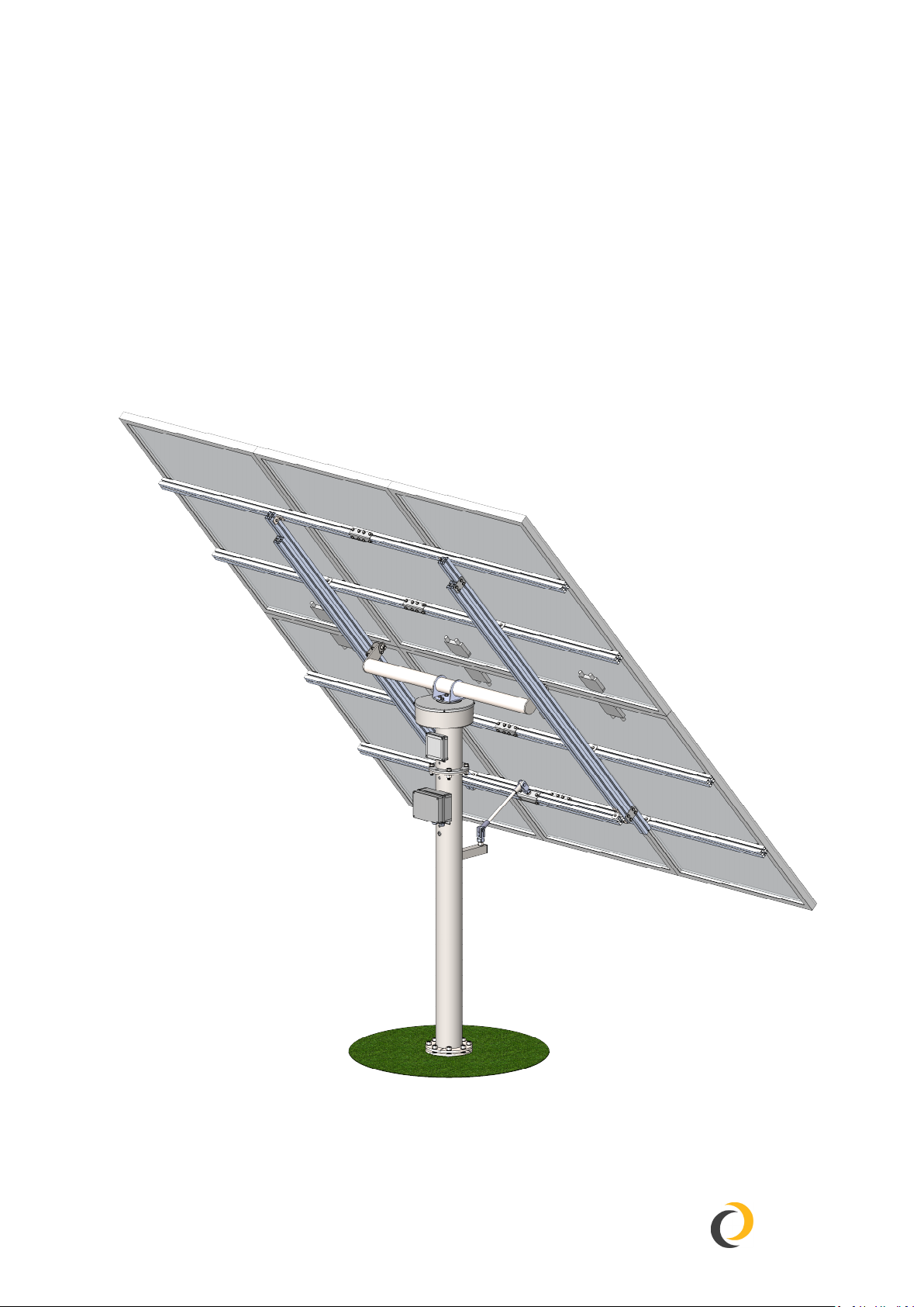
QUICK ASSEMBLY GUIDE
PV-6
HELIOMOTION
HelioZenit
Revision 1, 2021
1x
1x
1x
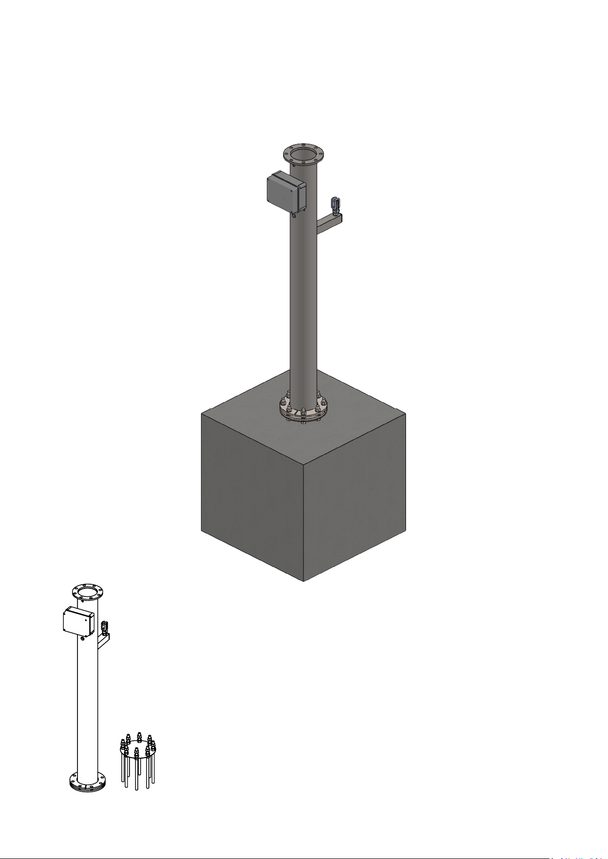
PART I - FOUNDATION

Rod unit
1x
2
1
3
Fill the hole with concrete up to a few
centimeters below ground level.
Make a hole for the concrete at your
chosen location. The hole for a PV-6
should be at least 80x80 cm, 1 m
deep (~600 liter).
Push the rod unit into center of the
concrete and let the flange rest on
top of the concrete. Use a spirit level
to align the flange horizontally.
Allow the concrete time to harden
before assemling the remainder of
the power plant. The concrete can
be covered with sand after it has
cured for 2 weeks.
Soil founda�on
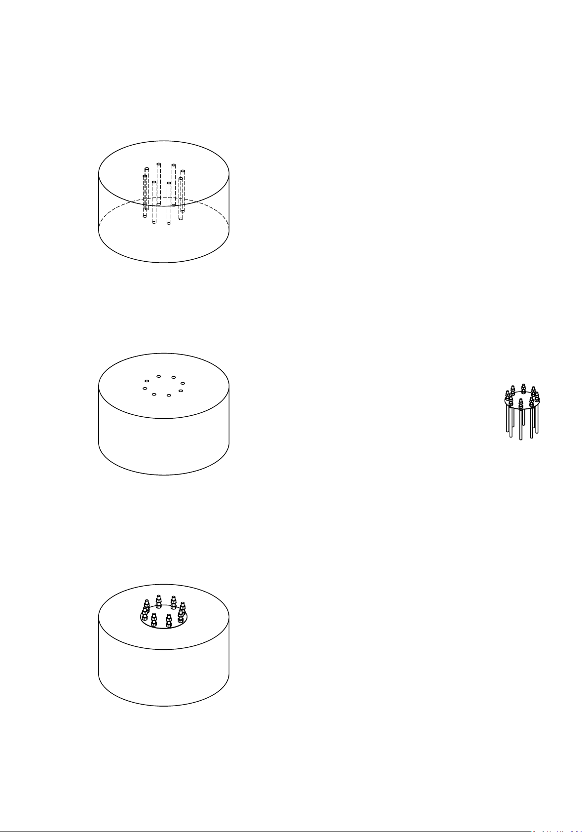
Rod unit
2
1
3
Make sure the rod unit fits well into
the holes.
Drill eight holes vertically into the
bedrock using the rod unit as a
template. Make the holes 20 mm
wide and 250 mm deep. Use
compressed air to remove any
debris and water from the holes to
ensure a clean bonding surface.
Fill the holes 2/3 full with chemical
anchor adhesive (400-500 ml). Push
the rod unit into the holes and give
the adhesive time to cure before
continuing the assembly.
Bedrock foundation
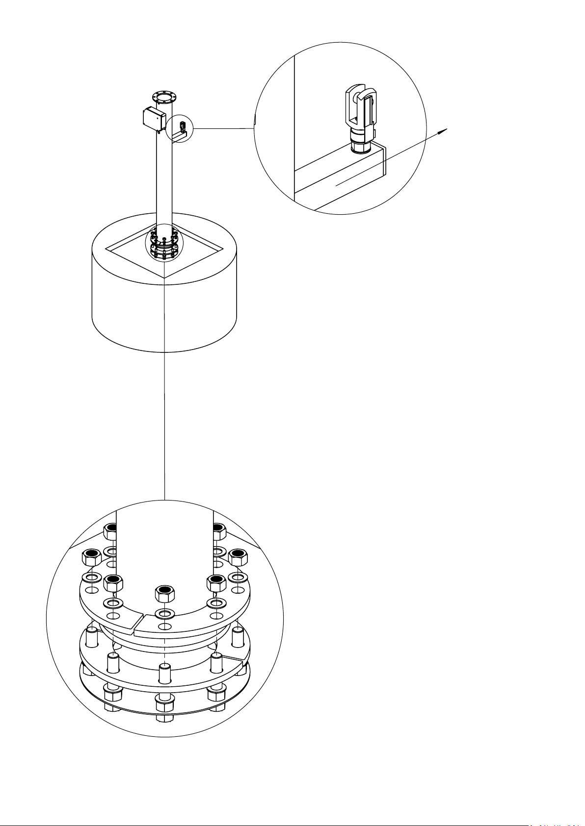
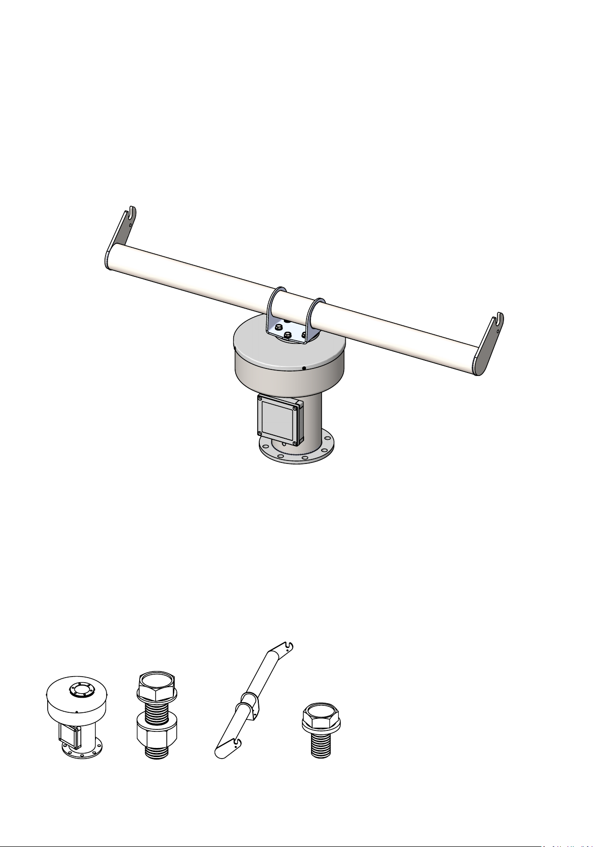
1x
1x
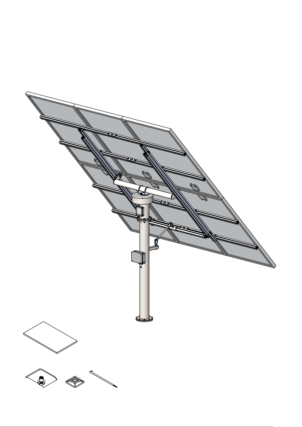
1. Mount the column including the bottom
flange on the rod unit as illustrated.
Column needs to be turned so that the
square tube faces true south in the northern
hemisphere or true north in the southern
hemisphere. To do so follow these steps:
2. Launch the compass app on your smart
phone. This compass is GPS compensated,
making it more accurate than a regular
compass.
3. Align the phone to true south (or north)
according to the compass.
4. Rotate the column so that the edge of the
tube lines up with the edge of the phone.
Make sure the compass is not distorted by
being too close to any metal objects.
This alignment can be fine-tuned after the
installation is complete and the tracker has
turned towards the sun.
4
5. Adjust bottom nuts to
horizontally align the column's
upper flange using a spirit
level.
6. Tighten top nuts and then
bottom nuts to secure the
column.
South
1x 1x 6x
4x
PART II - TRACKER

6x
4x
1x
1x
1
2
2x 1x
1x
20x
2x 4x
8x
1x
2x
2x
4x
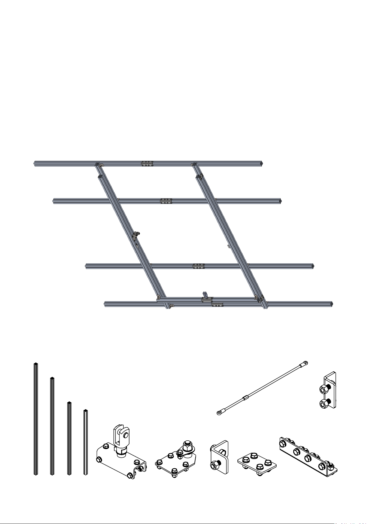
PART III - FRAMEWORK

2300mm
2000mm
150mm 150mm
2x
2x
4x
2
1
2x
960mm 960mm
2x
45mm
45mm
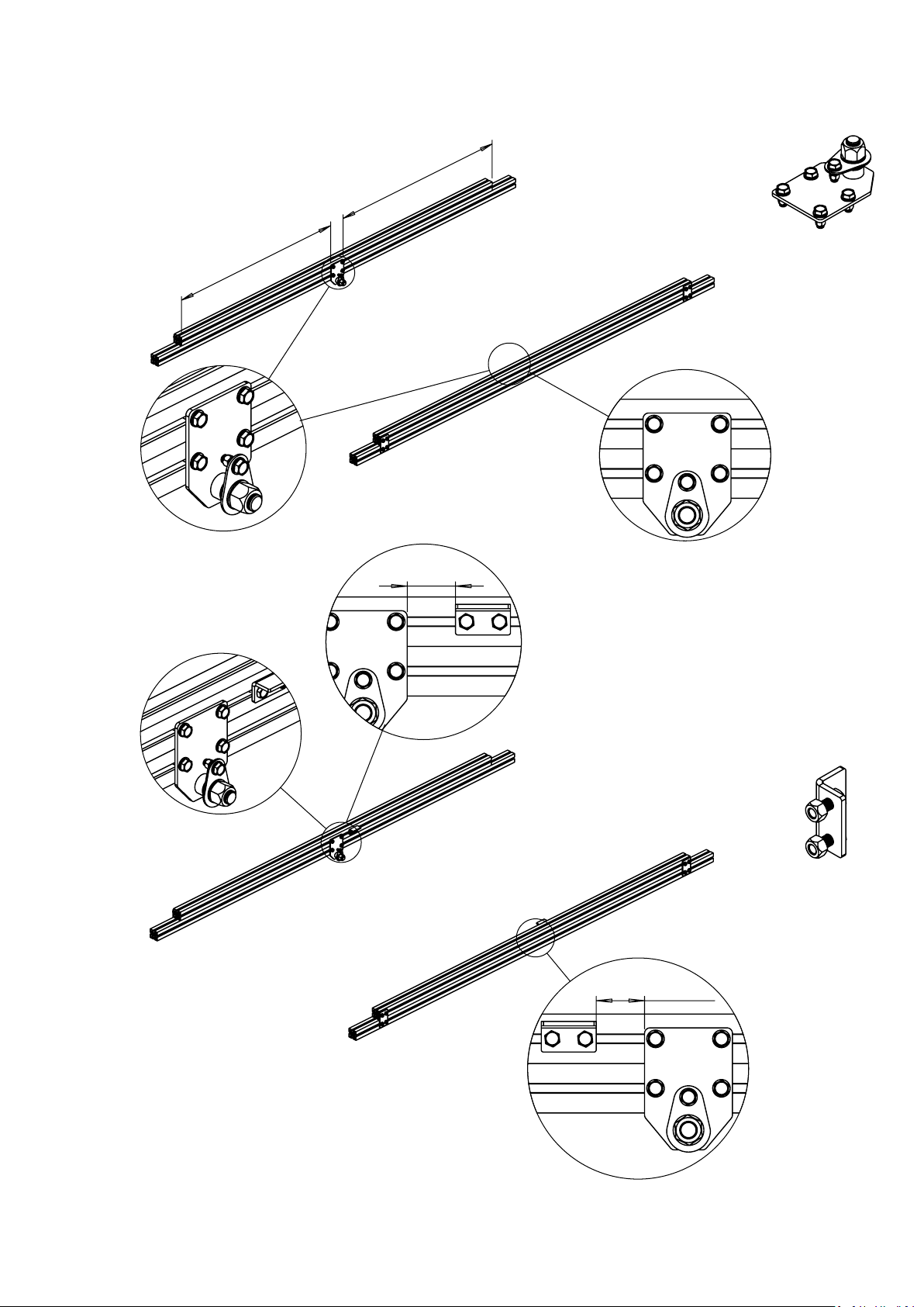
4
3
592mm
592mm
1x
1x
4x
1
2
1x
5
6

16x
45mm
600mm 600mm
45mm
Tighten the M16 nut
slightly on both sides
8
7
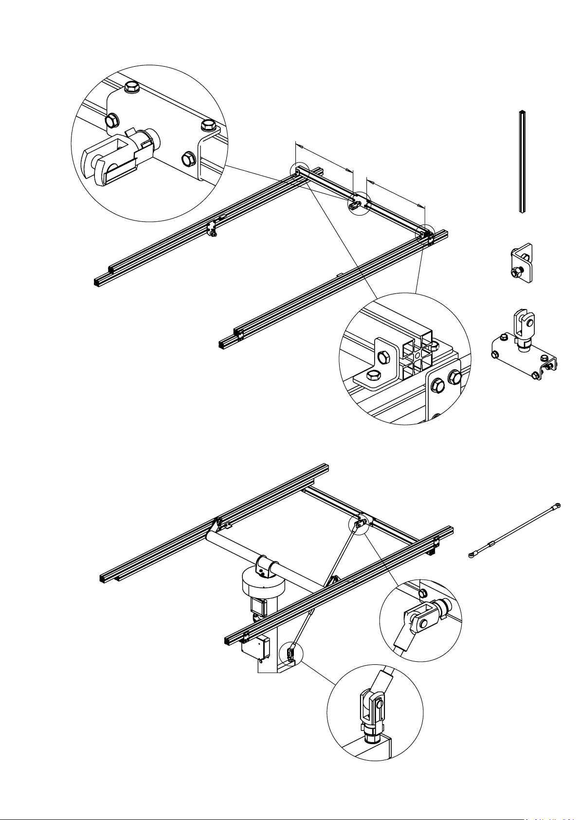
1
2

645mm 645mm
X
1324mm
X
X = (Panel width * 3 - 1324)/2
4x
9
6x
10x
10x
24x
PART IV - PANELS
6x
24x
355mm
355mm
B
C
E
2
1
3. Repeat these steps for the
remaining panels.
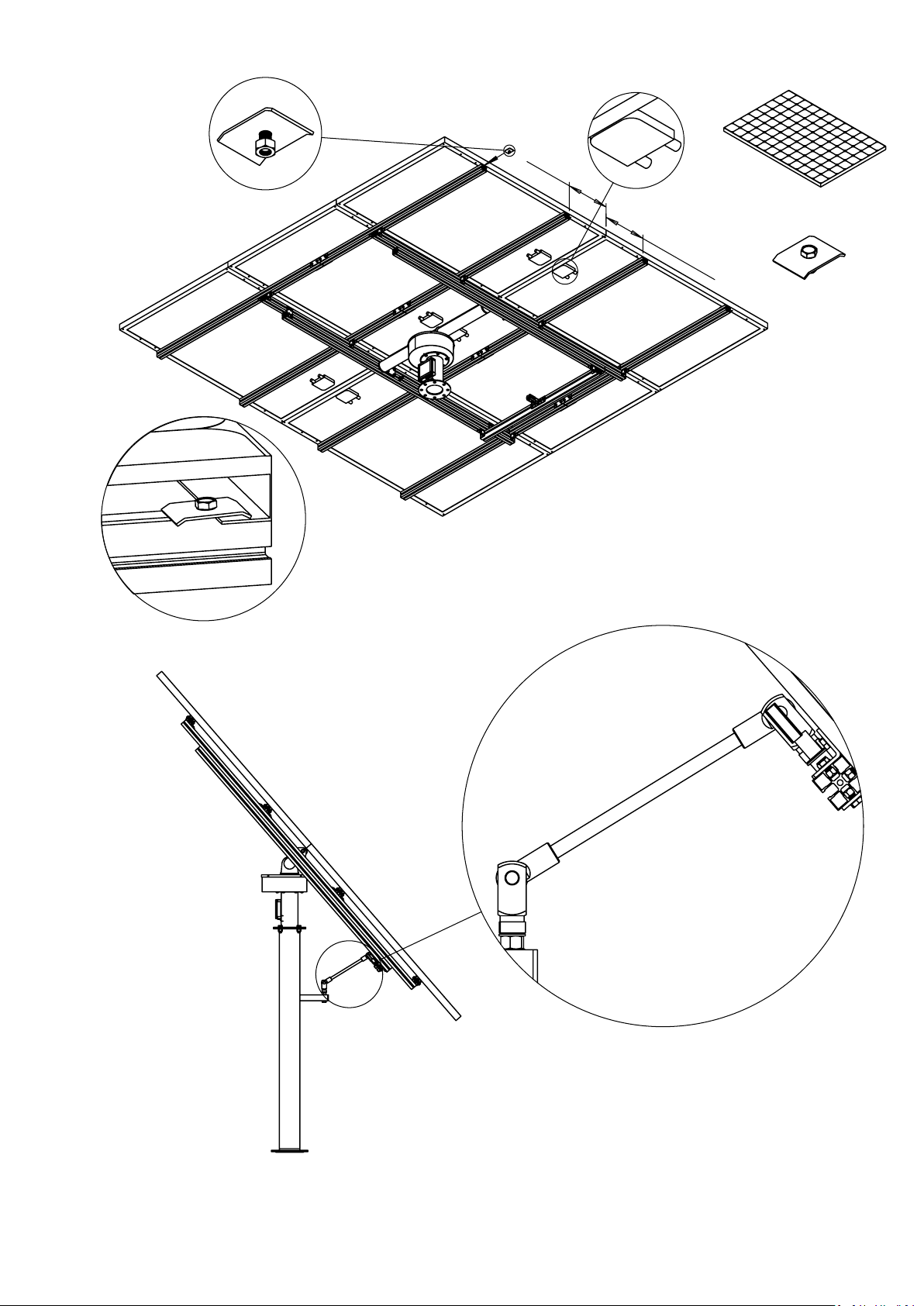
1. Lift a panel onto the frame
as illustrated with the cable
box (B) facing inwards.
2. Lock the panel to the frame
with four panel clamps (C).
Remove the extension rod and attach only the
black angle rod. Make sure to prevent the panels
from swinging downwards when changing the rod.
Leave both fork joints (F) and one of the clevis eye
mating pieces (E) unscrewed half a turn to allow for
full range of movement.
Make sure to bend both retaining pins so that the
fork joint bolts are held in place.
F
C
10x
10x
40V
9A
Series
_
+
_
+++
+
+
__
_
_
_
+
M
M
1x
J
3x
M
3
240V
9A
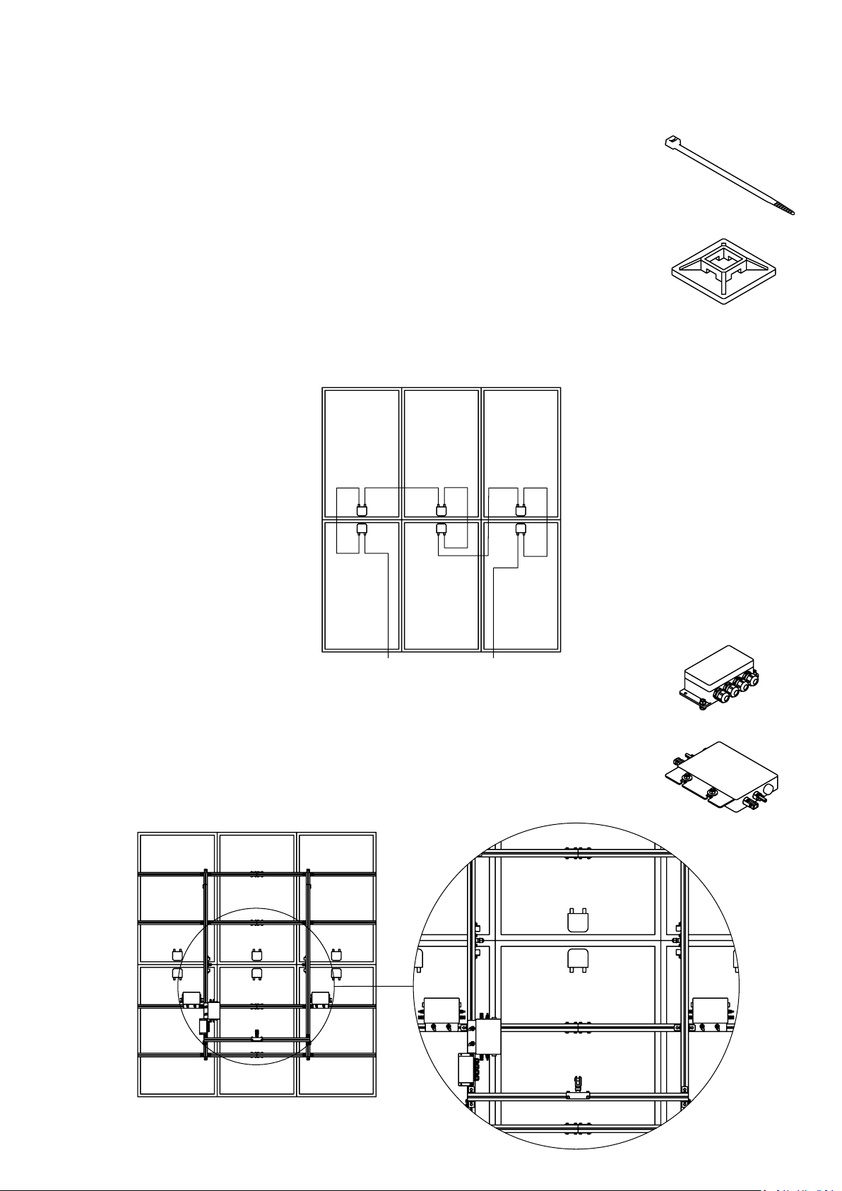
1. Attach PV cables to the frame using cable ties and
self-adhersive clip anchors.
2. Have the electrician connect the PV cables together
according to application. Standard applications are
listed below.
String inverter
Grid-tied string inverters generally supports a high voltage
PV input. Therefore, all 6 panels are typically connected
in series when using a string inverter.
Microinverter
Grid-tied microinverters typically have 1, 2 or 4 PV inputs.
Mount the microinverters (M) and a junction box (J) similar
to the illustration below, so that they are easy to connect
to the panels.
M
J
AC switch (S)
Utility AC (U)
L1
N
24VDC
L
N
+
-
Transformer (T)
Ground (G)
L2 L3
L3L2L1
Neutral
GG
K
AC
5x2.5mm
²
L
Line 1
24VDC
2x1mm
²
K
M
M
M
G G G G
NNNN
L3L2L1
L1 L2 L3
Neutral
Ground
Line in
Line out
A
Grid-�ed system with microinverters
The PV solar panels, microinverter (M) and utility AC (U) must be connected
by a certified electrician. However, preparation work may be done by a
layman as long as local code requirements are followed.
AC wires must be at least 1.5mm² thick and use an outdoor cable. Be
mindful of the AC labels and wire colors: Neutral (N) is blue, Phase 1 (L1)
brown, Phase 2 (L2) black, Phase 3 (L3) gray and ground (G) green-yellow.
If using a 1-phase system the electrical
wiring can be simplified by connecting
the microinverters together as illustrated here.
A
M
M
M

1. Acquire an outdoor underground cable long enough to reach from the
junction
box (K) on the column to the nearest fuse box inside the house. A
1-phase system needs a cable with two wires plus a surrounding shield
(1-phase cable), whereas a 3-phase system needs a cable with four wires
plus the shield (3-phase cable). The thickness of the wires should be at least
2.5mm² for cable lengths up to 40 meter or 6mm² for cable runs up to 100
meter. Indoor cable sections can use an indoor cable of the same size and
with the same number of conductors. Please consult your electrician for the
exact cable to use according to local code requirements.
2. Wire the cable from the junction box (K) to the fuse box. A strong string
can be used to pull the cable up through the bottom of the column and
out of the hole beneath the junction box. It is recommended to pull under-
ground sections through a cable duct. The duct needs to be burried so
that the top of the duct is 35 cm below ground. If the cable runs over bed-
rock it needs to be protected by a strong hose (or a metal U-profile).
3. Make sure that all cable sections above ground are properly attached
and protected so the cable cannot be accidentally moved or damaged.
Sections coming out of the ground need to be protected by for example
a metal U-profile.
4. Fill out and attach the included self adhesive warning labels. These labels
need to be provided near the solar installation, the fuse box, and the utility
meter, to indicate the presence of on-site generation and the placement
of the AC switch (S).
Contact a certified electrician and have them inspect the installation
and carry out the remaining tasks.
1. Make the electrical connections as illustrated on the previous page.
2. Connect the AC cable to the selected phase(s) through fuse(s) in the
fuse box.
3. Connect the solar panels to the PV input terminals of the microinverters.
4. Turn on the AC switch (S) in the junction box to power the inverter(s) and
solar tracker. It takes a few minutes for the tracker to find a GPS signal
before it start to track the sun.
5. Check the status lights on the inverter(s). When a solar panel is connec-
ted its LED becomes red. When the AC side is connected and powered the
LED starts blinking red. Grid feed-in starts after about 30 seconds during
sunshine indicated by the LED either blinking green (optimizing output) or
being continously green (output optimized).
Grid-�ed system with microinverters

A
24V+
PV+PV-
24V-
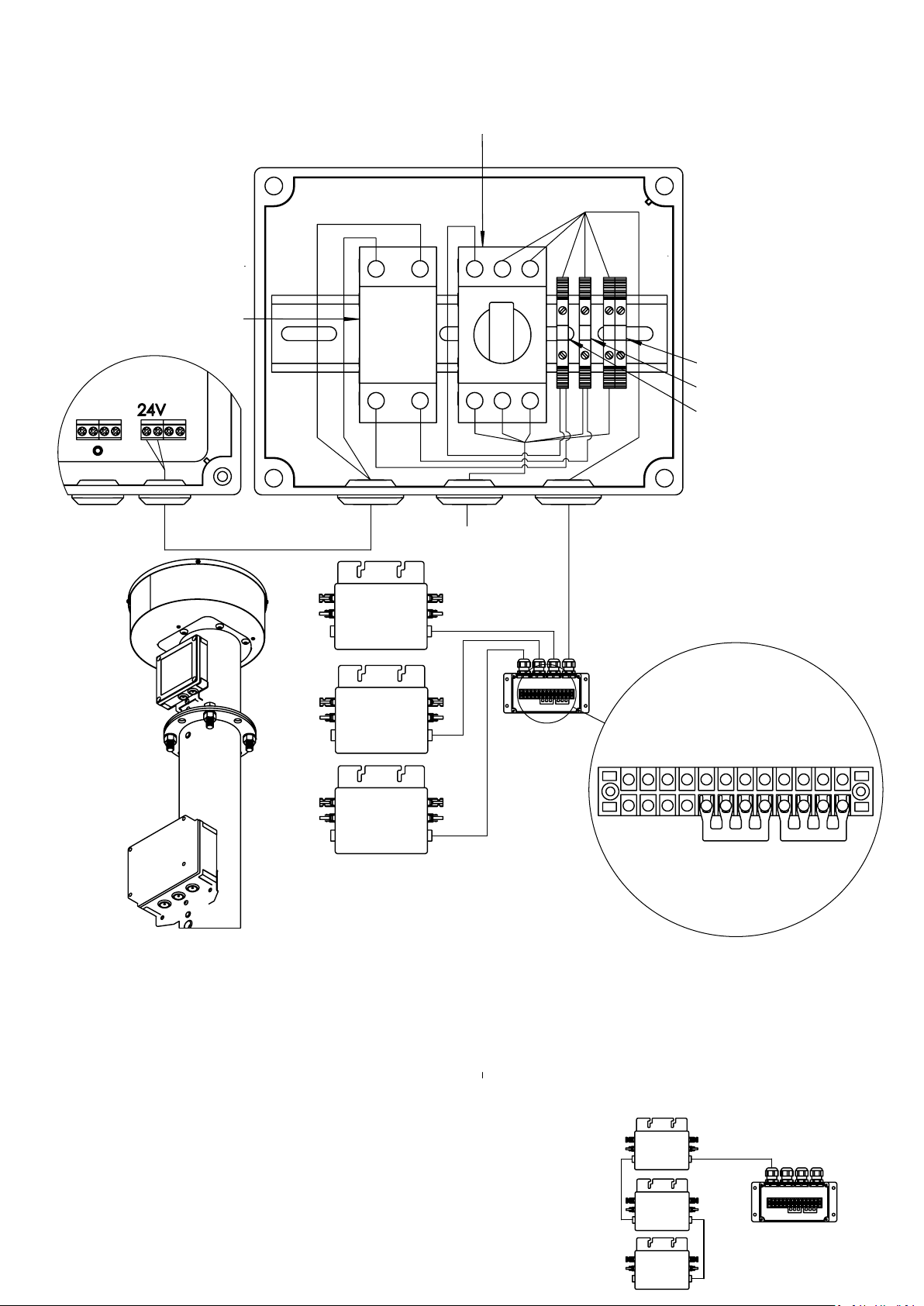
If the string inverter and 24VDC transformer is placed
away from the solar installation the junction box (K)
can be wired as shown above.
If the string inverter is placed on the column of the
solar installation the 24VDC transformer can be added
to the outdoor junction box (K) along with AC
breakers.
Grid-�ed system with string inverter
K
G
PV (x2)
Ground (G)
G
DC (x4+G)
²
24VDC
2x1mm
K
A
Other HelioZenit Solar Panel manuals


Popular Solar Panel manuals by other brands


REC
REC TwinPeak 2S Mono 72 Series installation instructions

Flexsolar
Flexsolar C100 Instruction manual & warranty

Energizer
Energizer HardCase Sunpack 120W user guide

solarwatt
solarwatt EasyIn 60M Series installation instructions

Mission Solar Energy
Mission Solar Energy MONO Series Installation and user manual

Wiedenmann
Wiedenmann Favorit XP Translation of original operating instructions