Helm GT-L 80 G 412 User manual

DSGTL80G412001_202306Montageanleitung / Installation instructions
HELM GT-L 80 G 412
Schiebetürsystem für Flügel bis 80 kg, Wandmontage mit Verblendung
Sliding door system for leaves up to 80 kg, wall installation with pelmet
DE / EN
HELM
geprüft nach DIN EN 1527:2013 (200.000 Zyklen)
maximales Flügelgewicht: 80 kg
für Einscheibensicherheitsglas (ESG) und Verbundsicher-
heitsglas (VSG aus zwei Mal ESG) geeignet
Flügelstärke: ESG 8/10 mm, VSG 8,76/10,76 mm
das Verhältnis der Türhöhe zur Türbreite darf 2,5:1 nicht über-
schreiten
alle Abmessungen in Millimeter
Wichtiger Hinweis zur Vermeidung von Personen-
und Sachschäden
Verwendung Glastüren
Gläser mit selbstreinigender Beschichtung dürfen mit unse-
ren Beschlägen nicht verwendet werden.
Glastüren und Glaselemente, die Beschädigungen aufweisen
(z. B. Kantenverletzungen, muschelförmige Ausbrüche oder
Kratzer), dürfen nicht verbaut werden.
Es ist auf die richtige Auswahl der Beschläge zu achten.
Die Spaltmaße sind so einzustellen, dass allseitig ein Kon-
takt mit harten Werkstoen verhindert wird.
Die Notwendigkeit eines Kantenschutzes für Kanten über
dem Boden bzw. an den Längskanten muss geprüft werden.
Für einen ordnungsgemäßen und sicheren Ge-
brauch dieser Anleitung folgen. Für späteres Nach-
schlagen aufbewahren.
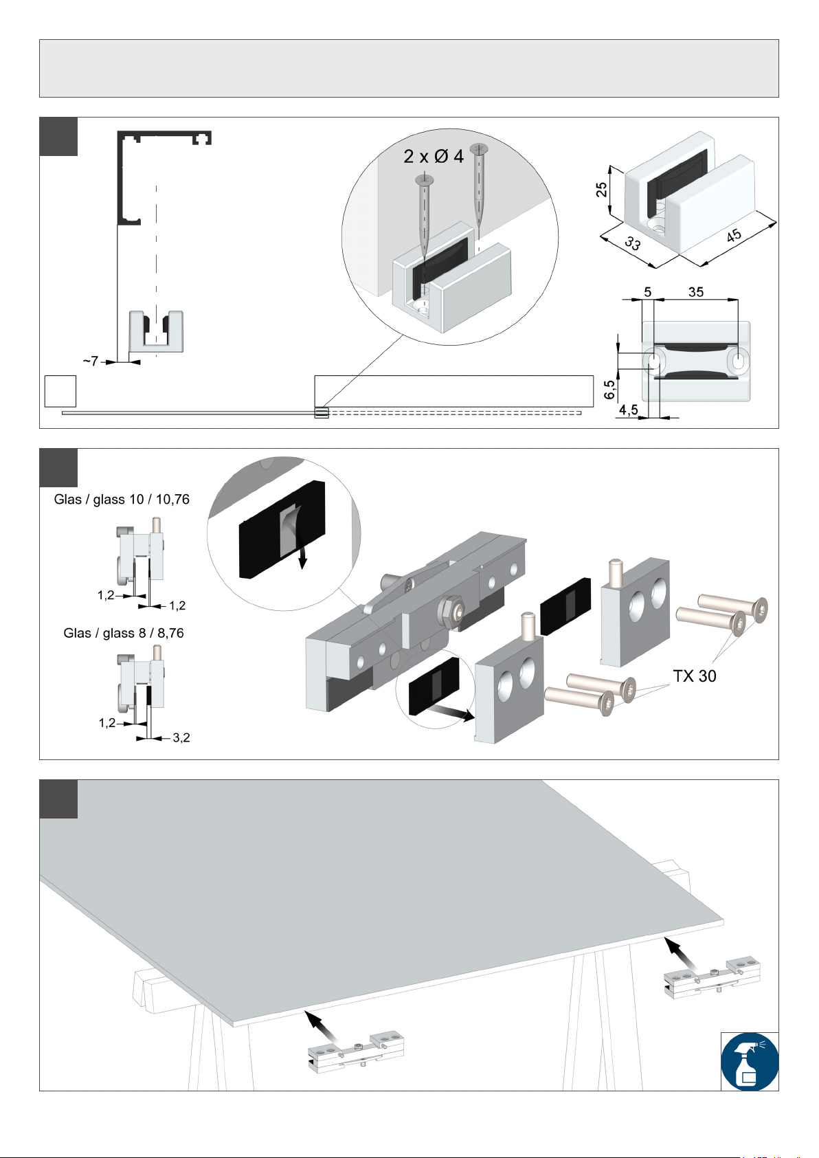
Lauächen der Laufschiene reinigen
Die Glasscheibe im Bereich der Klemmächen so-
wie die Glasklemmstücke z. B. mit UV-Spezialreini-
ger oder Aceton reinigen, bis sie sauber und fettfrei
sind.
Bei Verwendung von VSG:
In alle Befüllungsbohrungen (Vorder- und Rücksei-
te) Zweikomponentenkleber einfüllen.
Hinweis: Bitte die Hinweise auf dem Beipackzettel
des Zweikomponentenklebers beachten.
2
Technische Informationen / Sicherheitshinweise
Über diese Anleitung
Diese Anleitung beschreibt die Montage des Schiebetürsystems
HELM GT-L 80 Glas - Wandmontage mit Verblendung. Die Monta-
ge wird am Beispiel einer rechtsönenden Tür gezeigt. Die Monta-
ge für eine linksönende Tür erfolgt entsprechend spiegelbildlich.
Bestimmungsgemäßer Gebrauch/Verwendung
Der Schiebetürbeschlag ist ausschließlich für den Einsatz in
trockenen Innenräumen im Personendurchgangsbereich vor-
gesehen.
Handbetätigte Schiebeelemente nur an den hierfür vorgese-
henen Türgrien und Türdrückern önen und schließen.
Handbetätigte Schiebeelemente nicht zuwerfen und nicht sto-
ßen, sondern langsam in die gewünschte Position führen.
Eine anderweitige Verwendung gilt als nicht bestimmungsge-
mäß und führt zum Erlöschen sämtlicher Haftungs- und Ge-
währleistungsansprüche.
Sicherheitshinweise
Die Montage und Inbetriebnahme ist nur von Fachpersonal
auszuführen.
Bei der Montage ist geeignete Schutzkleidung zu tragen.
Wir empfehlen Ihnen die Montage mit 2 Personen durchzu-
führen.
Es besteht Verletzungsgefahr durch sich bewegende Teile im
Fahrbereich des Türblatts.
Anforderungen an die Wand-, Decken- und Bodenbeschaen-
heit und das Befestigungsmaterial
Die Tragfähigkeit der Wand bzw. Decke muss für die stati-
schen und dynamischen Anforderungen ausreichend dimen-
sioniert sein.
Die Unterkonstruktion muss dauerhaft tragfähig, plan und lot-
recht sein (max. Toleranz: 2 mm pro Meter).
Das Befestigungsmaterial muss für die Unterkonstruktion und
für die statischen und dynamischen Anforderungen geeignet
sein. Die technischen Hinweise des Befestigungsmaterials
beachten.
Das Befestigungsmaterial ist nicht im Lieferumfang enthalten.
Wartung
Die Beschlagteile sind nahezu wartungsfrei und pegeleicht. Die
Schiebetürbeschläge müssen regelmäßig auf Anzeichen von Ver-
schleiß und Beschädigungen überprüft werden. Anlagen, bei de-
nen eine Reparatur notwendig ist, dürfen nicht weiter betrieben
werden. Des Weiteren ist ein fester Sitz aller Befestigungselemen-
te wie Schrauben, Muttern etc. zu überprüfen und eine Funktions-
prüfung durchzuführen. Notwendige Reparaturarbeiten sind durch
fachkundiges Personal bzw. Fachrmen auszuführen. Hierbei sind
ausschließlich originale Ersatzteile zu verwenden.
Reinigung
Die Reinigung von eloxiertem Aluminium darf nicht mit Säuren
oder anderen alkalischen Reinigern erfolgen. Weiterhin sollten zur
Reinigung keine Scheuermittel und auch keine Stahlwolle verwen-
det werden. Staub, Flecken und leichte Verschmutzungen lassen
sich mit lauwarmem Wasser entfernen. Hartnäckige Schmutz-
stellen, wie Gips- oder Zementreste, lösen sich leicht, wenn Sie
einige Spritzer eines herkömmlichen Netzmittels (z. B. Geschirr-
spülmittel) ins Wasser geben. Ein kleiner Spritzer vom Netzmittel
reicht aus, um gute Ergebnisse bei der Reinigung zu erzielen. Wir
weisen ausdrücklich darauf hin, dass die Eloxalschicht mit Mörtel
oder Kalkwasser beschädigt werden kann. Es ist also wichtig, dass
der Eimer mit Wasser absolut keine anderen Stoe enthält, außer
einem Netzmittel.
Entsorgung
Die Demontage des Systems erfolgt anhand der Montageschritte
in umgekehrter Reihenfolge der Montage und muss durch sach-
kundiges Personal erfolgen. Entsorgen Sie das Produkt umwelt-
gerecht. Beachten sie dabei die geltenden nationalen gesetzlichen
Vorschriften.
HELM 3
Technical information / Safety instructions
About these instructions
These instructions describe the installation of the sliding door sys-
tem HELM GT-L 80 glass - wall installation with pelmet. The instal-
lation is shown using the example of a right-opening door. For left-
opening doors, the installation must be carried out in mirror image.
certied according to DIN EN 1527:2013 (200.000 cycles)
max. leaf weight: 80 kg
suitable for tempered safety glass (TSG) and laminated safety
glass (LSG consisting of two TSG panels)
leaf thickness: TSG 8/10 mm, LSG 8,76/10,76 mm
the ratio of door height to door width must not exceed 2,5:1
all dimensions in millimeter
For safe and proper use, follow these instructions.
Keep them for future reference.
Clean the tread of track
Important advice to prevent injury to persons and
damage to property
Use glass leaves
Glass panels with self-cleaning coating cannot be used with
our ttings.
Glass doors and glass elements that exhibit damages (e.g.
edge damage, shell-shaped bursts, chips or scratches) must
not be installed.
Ensure the correct selection of the ttings.
Set the gap dimension so that contact with hard materials is
prevented on all sides.
Check the necessity of an edge protection for edges above
the oor or on longitudinal edges.
Clean the glass panel in the clamping areas as well
as the glass clamps e. g. with special UV cleaner or
acetone until they are free of grease.
When using LSG:
ll all lling holes (front and back side) with two-com-
ponent adhesive.
Note: Please follow the instructions in the manual of
the two-component adhesive.
Intended use
The sliding door ttings are only suitable for dry indoor spaces.
Open and close hand-operated sliding elements using only
the intended door handles and ush pulls.
Do not slam and shove hand-operated sliding elements; slow-
ly guide them into the desired position.
Any other use is considered improper and will invalidate all
liability and warranty.
Safety instructions
Installation and commissioning may only be carried out by
qualied personnel.
Suitable protective clothing must be worn during installation.
We recommend the installation to be carried out by two peo-
ple.
There is a risk of injury due to moving parts in the sliding area
of the door leaf.
Requirements for the wall, ceiling and oor and the xing ma-
terial
The load bearing capacity of the wall or ceiling must meet sta-
tic and dynamic requirements.
The substructure must be permanently capable of bearing
loads, at and plumb (max. tolerance 2 mm per metre).
The xing material must be suitable for the substructure and
meet the static and dynamic requirements. Refer to the tech-
nical instructions for the xing material.
The xing material is not included in the scope of delivery.
Maintenance
The hardware parts are almost maintenance-free and easy to
clean. The sliding door ttings must be checked regularly for signs
of wear or damage. Damaged systems may not be operated any
longer. Furthermore, all fastening elements such as screws, nuts,
etc. must be checked and a functional test must be carried out. Re-
pair work must be carried out by qualied personnel or specialist
companies. Only original spare parts are to be used.
Cleaning
Do not clean anodized aluminum with acids or other alkaline clea-
ners. Furthermore, scouring powder and steel wool should not be
used for cleaning. Dust, stains and light soiling can be removed
with lukewarm water. Persistent soiling such as gypsum or cement
remnants can be easily removed if you add a few squirts of a con-
ventional wetting agent (like dish washing liquid) to the water. A
small squirt of a wetting agent is sucient to obtain good results
during cleaning. We explicitly point out that the anodized coating
can be damaged by mortar and lime water. That means it is im-
portant that the bucket with water does not contain any substances
other than a wetting agent.
Disposal
Disassembly of the system is carried out in the reverse order of in-
stallation and must be performed by qualied personnel. The pro-
duct must be disposed of in an environmentally friendly manner.
Refer to the national statutory regulations.

HELM
~62
57
25
10±3,5 11±3,5
22
35
10[8]
~19
~33[35]
33
~7
FH
BH
4
Flügelhöhe / Leaf height
FH = BH – 11 – 10
Legende / Legend
FH Flügelhöhe / leaf height
BH Bohrhöhe / drill height
Einbauschnitt / Berechnungen
Drawing / Calculations

HELM 5
Berechnungen
Calculations
Flügelbreite / Leaf width
FB = LW + (2 x Ü)
FB min.
A + A = 650 mm, A + B = 650 mm,
B + B = 860 mm
Laufschienenlänge / Track length
LL = (FB x 2) – (1 x Ü) + (2 x 5)
Lichte Weite / Clear width
LW = LL – (2 x 5) – FB – (1 x Ü)
Legende / Legend
LL Laufschienenlänge / track length
LW Lichte Weite / clear width
Ü Überlappung / overlapping
FB Flügelbreite / leaf width
A
B
A
B
HELM6
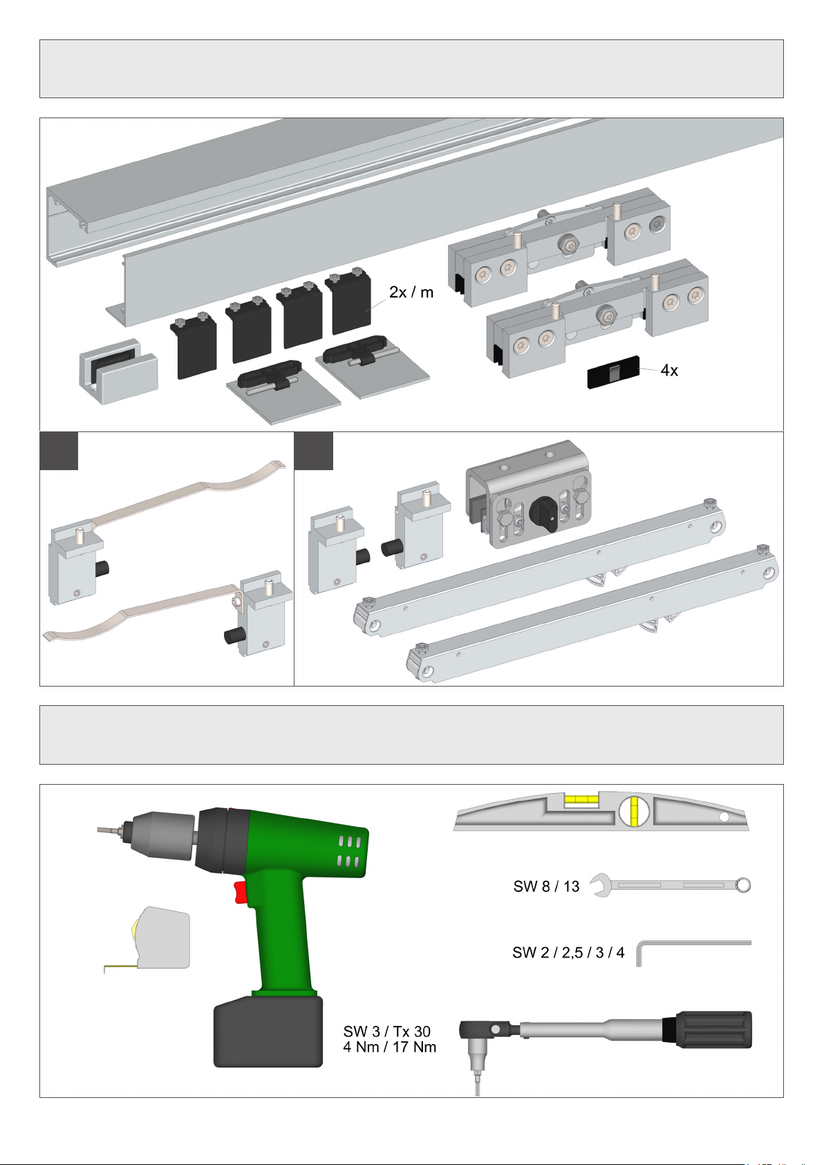
Benötigtes Werkzeug
Required tools
Lieferumfang
Scope of delivery
AB
HELM 7
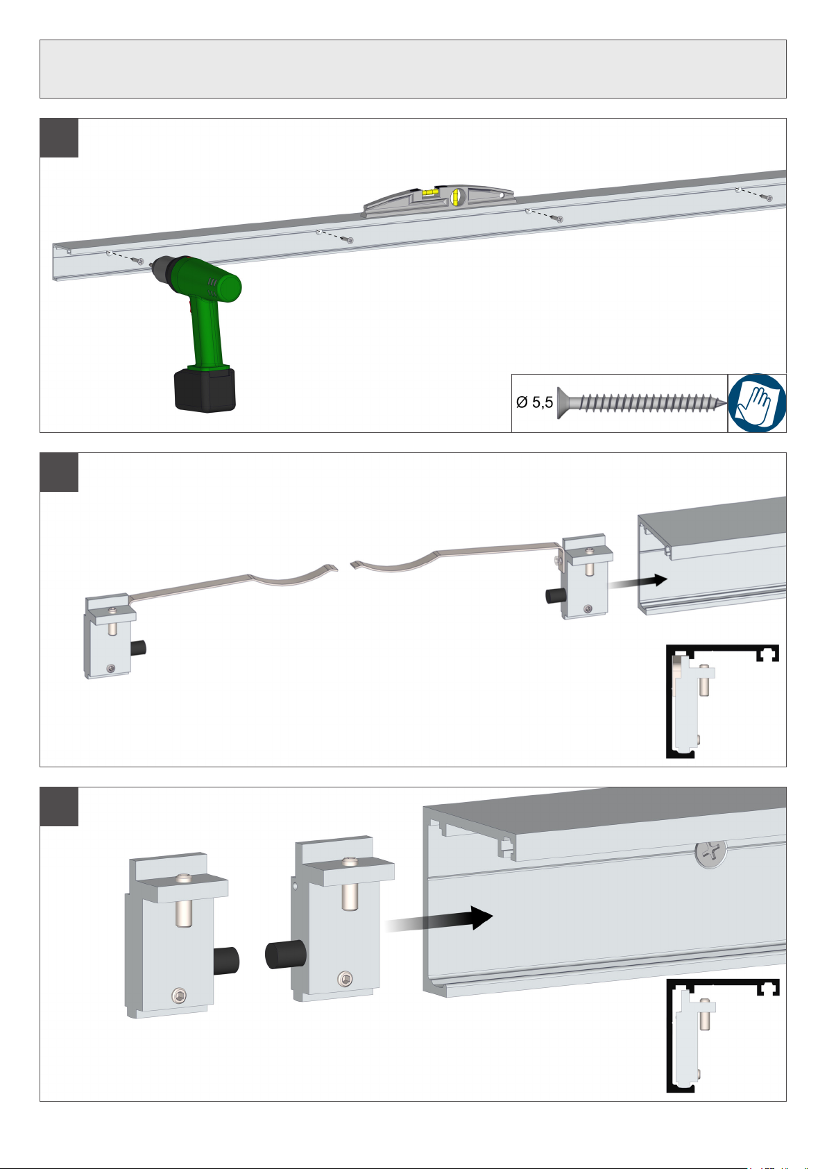
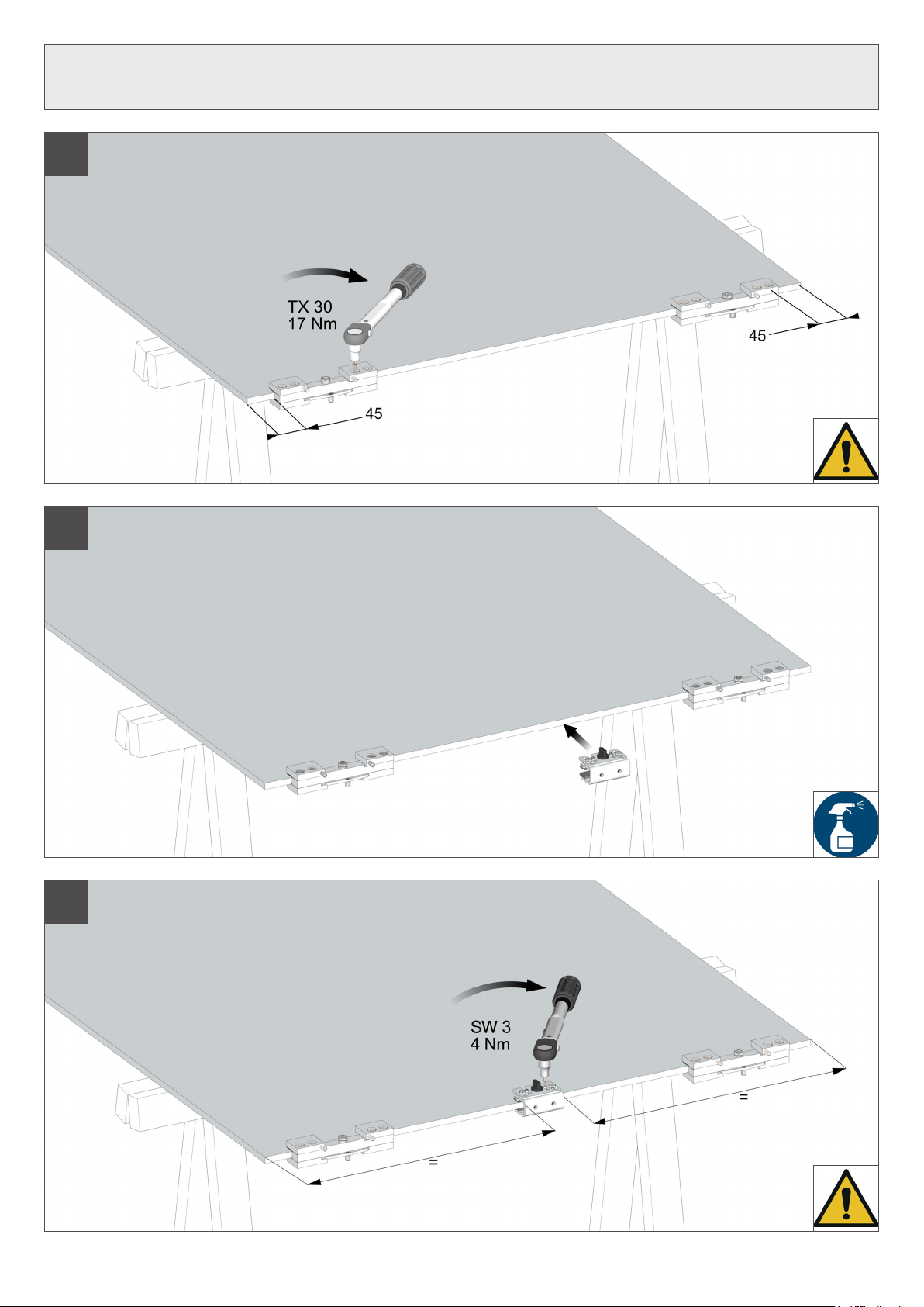
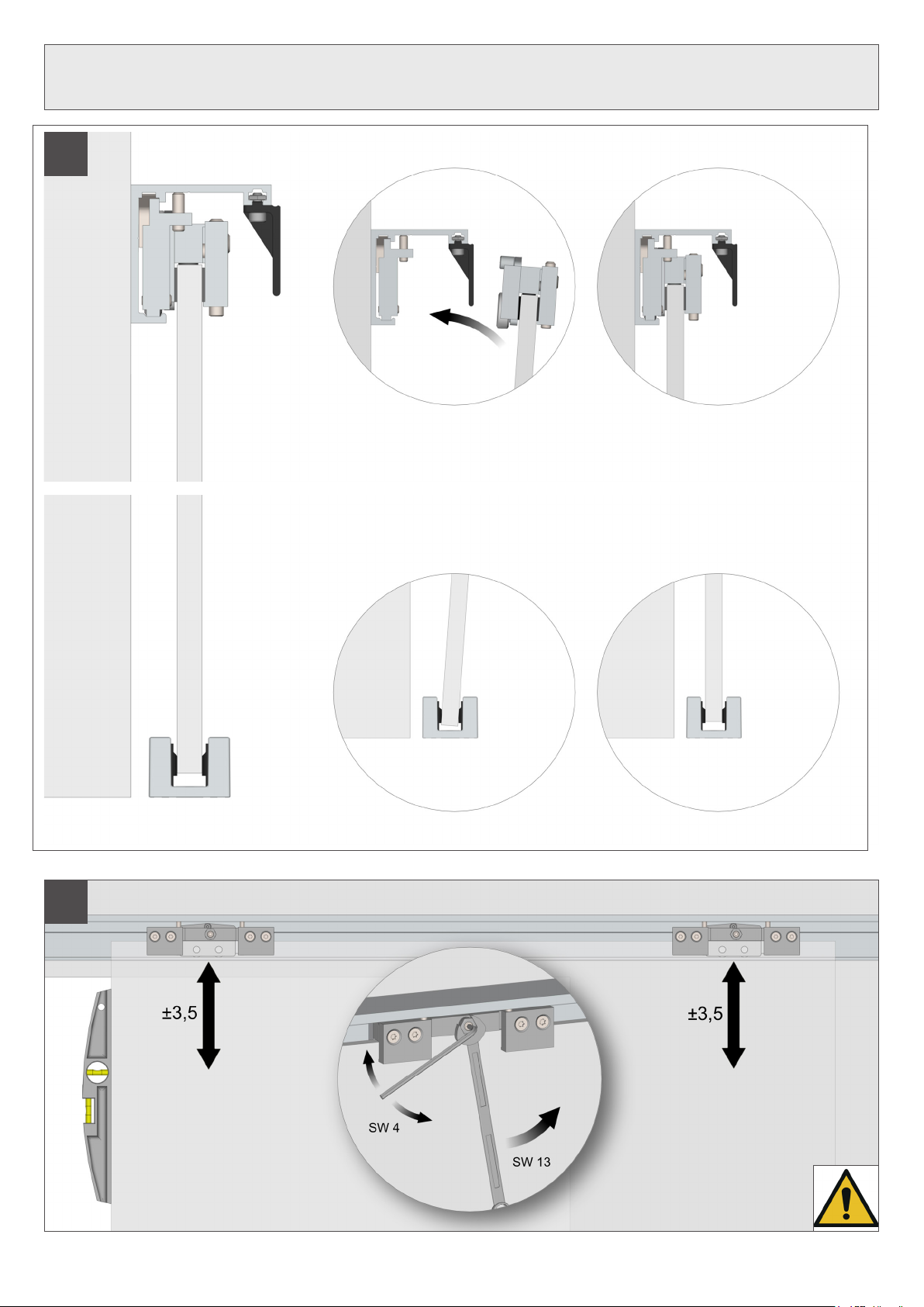
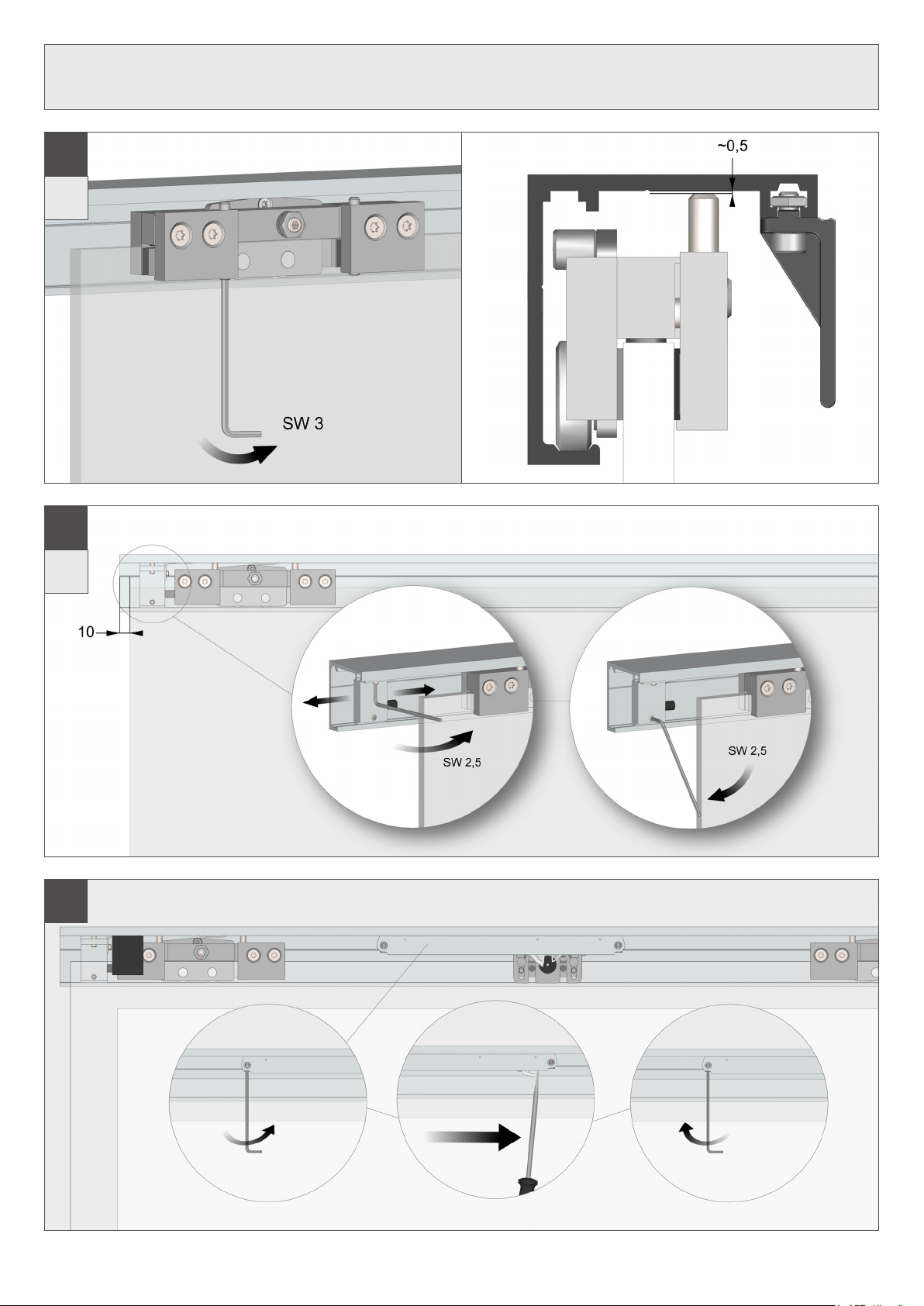
Montageschritte
Installation steps
1
2.A
2.B

HELM8
4.B
Montageschritte
Installation steps
3
4.A
HELM 9
5
Montageschritte
Installation steps
6
7
HELM10
Montageschritte
Installation steps
9.B
10.B
8
HELM 11
11
Montageschritte
Installation steps
12
HELM12
Montageschritte
Installation steps
14
13
2 x
15.B
2 x

HELM
16.B
13
Montageschritte
Installation steps
17.B
18.B

HELM14
23
2 x
Montageschritte
Installation steps
22
2 x
20 21
19


Woelm GmbH
Hasselbecker Str. 2 – 4
D-42579 Heiligenhaus
Tel. +49 (0) 2056 18-0
Fax +49 (0) 2056 18-21
www.woelm.de
Woelm Austria GmbH
Seewalchen 5 A
A-5201 Seekirchen
Tel. +43 (0) 6212 2502
Fax +43 (0) 6212 6995
www.woelm.at
This installation instructions supersedes
all previous installation instructions.
The technical specifications are up-
to-date. We reserve the right to make
modifications with regard to design
and styling which serve the purpose of
technical improvement. We appreciate
your understanding that we assume no
liability for any typing errors or any other
errors. The reproduction of this document,
in extracts or complete, is not permitted
without our express written permission.
Hiermit werden alle früheren Montage-
anleitungen ungültig.
Die technischen Angaben entsprechen
dem neusten Stand. Änderungen in
Konstruktion und Formgestaltung, die
dem Fortschritt dienen, behalten wir uns
vor. Wir bitten um Verständnis, dass für
Druckfehler oder Irrtümer keine Haftung
übernommen werden kann. Der Nach-
druck ist, auch auszugsweise, ohne
unsere ausdrückliche Genehmigung
nicht gestattet.
DSGTL80G412001_202306
Other Helm Door Opening System manuals

Helm
Helm GT-L 80 G 413 User manual

Helm
Helm GT-L 50 G 412 User manual

Helm
Helm MK-L 80 G 152 User manual

Helm
Helm MK-L 80 G 111 User manual

Helm
Helm MK-M 140 G 169 User manual

Helm
Helm MK-L 80 G 120 User manual

Helm
Helm GT-L 50 User manual

Helm
Helm MK-L 80 G 114 User manual

Helm
Helm MK-L 80 G 148 User manual

Helm
Helm GT-L 80 H 412 User manual


