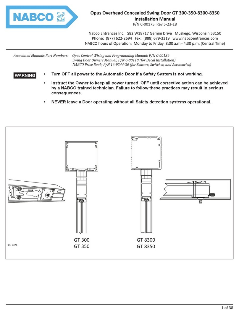
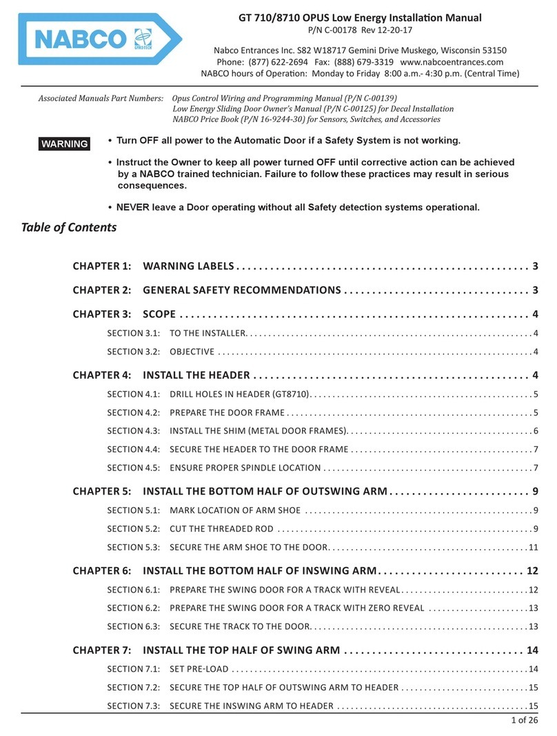
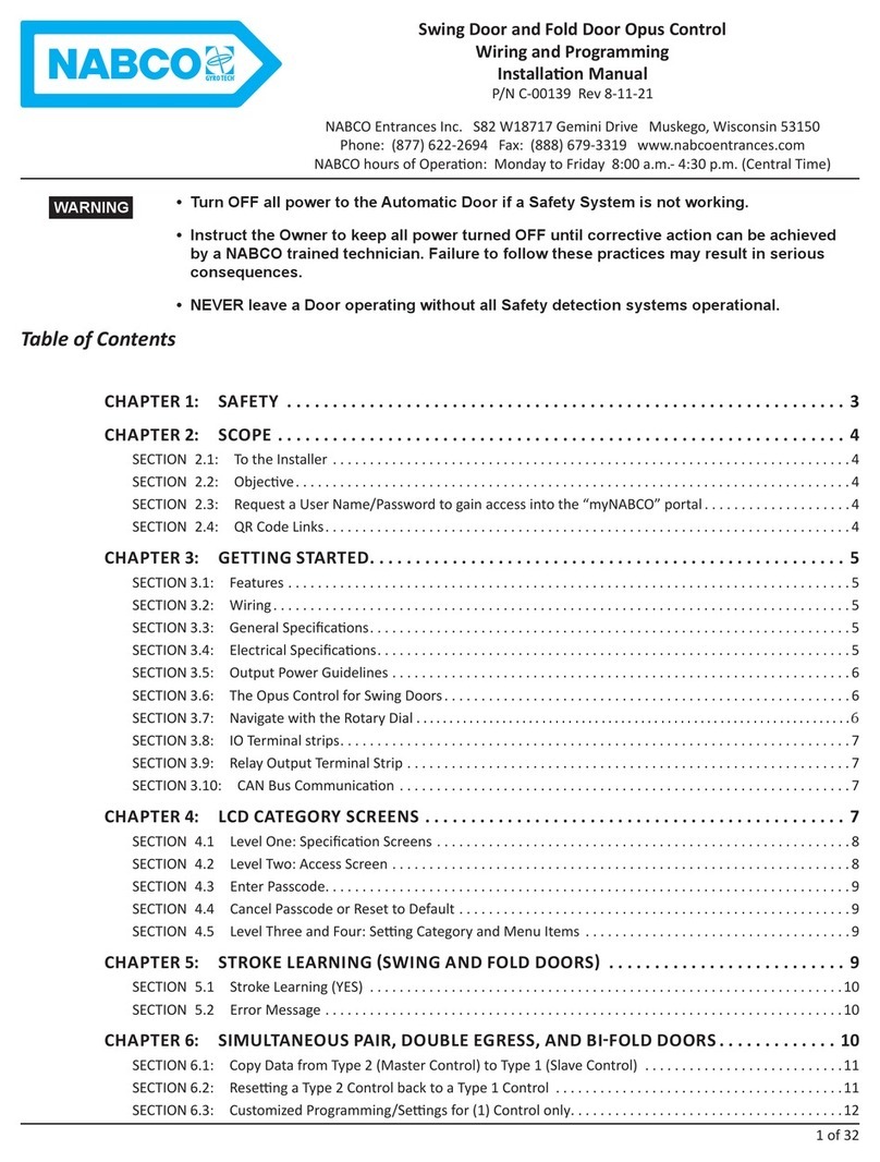
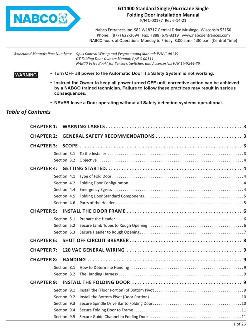
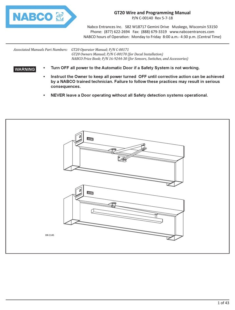
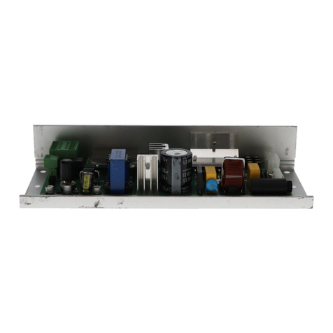
Nabco GYRO TECH GT-1175 Owner's manual

1 of 31
GT1175 Slide Door Opus Control
Wiring and Programming Manual
P/N C-00391 Rev 8-11-21
NABCO Entrances Inc. S82 W18717 Gemini Drive Muskego, Wisconsin 53150
Phone: (877) 622-2694 Fax: (888) 679-3319 www.nabcoentrances.com
NABCO hours of Operaon: Monday to Friday 8:00 a.m.- 4:30 p.m. (Central Time)
• Turn OFF all power to the Automatic Door if a Safety System is not working.
• Instruct the Owner to keep all power turned OFF until corrective action can be achieved
by a NABCO trained technician. Failure to follow these practices may result in serious
consequences.
• NEVER leave a Door operating without all Safety detection systems operational.
WARNING
Table of Contents
CHAPTER 1: SAFETY ............................................................. 3
CHAPTER 2: SCOPE .............................................................. 4
SECTION 2.1: To the Installer ......................................................................4
SECTION 2.2: Objecve ...........................................................................4
SECTION 2.3: Request a User Name/Password to gain access into the “myNABCO” portal . . . . . . . . . . . . . . . . . . . . 4
SECTION 2.4: QR Code Links .......................................................................4
CHAPTER 3: GETTING STARTED.................................................... 4
SECTION 3.1: Features ............................................................................4
SECTION 3.2: Wiring ..............................................................................5
SECTION 3.3: General Specicaons .................................................................5
SECTION 3.4: Electrical Specicaons ................................................................5
SECTION 3.5: Output Power Guidelines ..............................................................5
SECTION 3.6: The Opus Control for GT1175 Units ......................................................6
SECTION 3.7: Navigate with the Rotary Dial ...........................................................6
SECTION 3.8: IO Terminal strips .....................................................................6
SECTION 3.9: Relay Output Terminal Strip ............................................................7
SECTION 3.10: CAN Bus Communicaon .............................................................7
SECTION 3.11: Simultaneous Pair ...................................................................7
CHAPTER 4: LCD CATEGORY SCREENS .............................................. 7
SECTION 4.1 Level One: Specicaon Screens ........................................................7
SECTION 4.2 Level Two: Access Screen ..............................................................8
SECTION 4.3 Enter Passcode .......................................................................8
SECTION 4.4 Cancel Passcode or Reset to Default .....................................................9
SECTION 4.5 Level Three and Four: Seng Category and Menu Items ....................................9
CHAPTER 5: STROKE LEARNING ................................................... 9
CHAPTER 6: SIMULTANEOUS PAIR ................................................ 10
SECTION 6.1: Copy Data from Type 2 (Master Control) to Type 1 (Slave Control) ...........................10
SECTION 6.2: Reseng a Type 2 Control back to a Type 1 Control .......................................11
SECTION 6.3: Customized Programming/Sengs for (1) Control only .....................................11

2 of 31
GT1175 Slide Door Opus Control Wiring and Programming Manual www.NabcoEntrances.com
P/N C-00391 Rev 8-11-21
CHAPTER 7: SENSORS WITH MONITORING ........................................ 12
CHAPTER 8: PROGRAMMING MENUS ............................................. 12
SECTION 8.1: Base Sengs .......................................................................12
SECTION 8.2: Movement Sengs ..................................................................12
SECTION 8.3: Oponal Sengs ....................................................................13
SECTION 8.4: Output Sengs .....................................................................14
SECTION 8.5: Input Sengs .......................................................................15
SECTION 8.6: History Seng ....................................................................16
SECTION 8.7: Test Open ..........................................................................16
CHAPTER 9: COMMON PROGRAM ADJUSTMENTS .................................. 17
SECTION 9.1: Movement Sengs ..................................................................17
SECTION 9.2: Recycle Count “Reset”. . . . . . . . . . . . . . . . . . . . . . . . . . . . . . . . . . . . . . . . . . . . . . . . . . . . . . . . . . . . . . . . 17
CHAPTER 10: SHUT OFF CIRCUIT BREAKER......................................... 18
CHAPTER 11: GT1175 SLIDE DOOR WIRING DIAGRAMS .............................. 19
SECTION 11.1: Single Slide Door with Acusensor M and Holding Beam (w/monitoring) . . . . . . . . . . . . . . . . . . . . . .19
SECTION 11.2: Telescopic Slide Door with Acusensor M and Holding Beam (w/monitoring) . . . . . . . . . . . . . . . . . . 20
SECTION 11.3: Bi-Part Slide Doors with Two Opus Controls .............................................21
SECTION 11.4: 1175 OPUS, using Holding Beam for Break-Out (Telescopic Only) ...........................22
SECTION 11.5: 1175 Matching other Common Sensors to 1175 with OPUS ................................23
SECTION 11.6: Factory Wiring for using Acusensor M for Sidelite Safety ..................................24
SECTION 11.7: Opus with 1175 Electric Lock .........................................................25
SECTION 11.8: Opus with 1175 Magnec Lock .......................................................26
SECTION 11.9: Change Slide Door Mode with Remote Switch ...........................................27
SECTION 11.10: Infrared Holding Beams ............................................................28
SECTION 11.11: Wiring a Card Reader, or secure Acvaon Device, to 1175 ...............................29
CHAPTER 12: TROUBLESHOOTING ................................................ 30

3 of 31
www.NabcoEntrances.com GT1175 Slide Door Opus Control Wiring and Programming Manual
Rev. 8-11-21 P/N C-00391
CHAPTER 1: SAFETY
SECTION 1.1: Warning Labels
Warning labels are universal and used to alert an individual of potenal harm to one’s self or to others. The following warning labels
are listed in a hierarchy order that denes the most potenal danger rst, and the least potenal danger last.
Indicates potentially dangerous situations. Danger is used when there is a hazardous situation
where there is a high probability of severe injury or death. It should not be considered for
property damage unless personal injury risk is present.
Indicates a hazardous situation which has some probability of severe injury. It should not be
considered for property damage unless personal injury risk is present.
Indicates a hazardous situation which may result in a minor injury. Caution should not be
used when there is a possibility of serious injury. Caution should not be considered for
property damage accidents unless a personal injury risk is present.
Aenon: A situaon where material could be damaged or the funcon impaired.
Notice: Indicates a statement of company policy as the message relates to the personal safety or protecon of
property. Noce should not be used when there is a hazardous situaon or personal risk.
Note: Indicates important informaon that provides further instrucon.
SECTION 1.2: General Safety Recommendaons
Disconnect all power to the junction box prior to making any electrical connections. Failure to
do so may result in serious personal or fatal injury. When uncertain whether power supply is
disconnected, always verify using a voltmeter.
Do not place nger or uninsulated tools inside the electrical controller. Touching wires or
other parts inside the enclosure may cause electrical shock, serious injury or death.
Read, study and understand the installation and operating instructions contained in or
referenced in this manual before operating. If you do not understand the instruction, ask a
qualied technician. Failure to do so may result in bodily injury or property damage and will
nullify all warranties.
The Ground wire from the Opus Control 120 VAC Harness, and the Incoming 120 VAC Ground
wire must be connected to the Ground screw located within the Swing door Header.
All electrical troubleshooting or service must be performed by trained, qualied electrical
technicians and comply with all applicable governing agency codes.
Do Not touch other parts of the Opus Control board with a screwdriver or anything else metal.
Damage to electrical circuitry may occur.
If the door appears broken or does not seem to work correctly, it should be immediately
removed from service until repairs can be carried out or a qualied service technician is
contacted for corrective action.
Notice: This manual, the owner’s manual and all other associated manuals must be given to and retained
by the purchasing facility or end user.
Notice: Wiring must meet all local, state, federal or other governing agency codes.
DANGER
WARNING
CAUTION
DANGER
DANGER
WARNING
CAUTION
CAUTION
CAUTION
CAUTION

4 of 31
GT1175 Slide Door Opus Control Wiring and Programming Manual www.NabcoEntrances.com
P/N C-00391 Rev 8-11-21
CHAPTER 2: SCOPE
SECTION 2.1: To the Installer
The purpose of this manual is to familiarize the installer with the proper installaon and operaon of this system. It is essenal that
this equipment be properly installed and operaonal before the door is used by the public. It is the installer’s responsibility to inspect
the operaon of the entrance system to be sure it complies with any applicable standards. In the United States, ANSI Standard 156.10
(Used to cover Full Energy doors) and ANSI Standard 156.19 (Used to cover Low Energy doors) apply. Other local standards or codes
may apply. Use them in addion to the ANSI standards.
If aer troubleshoong a problem, a sasfactory soluon cannot be achieved, please call Nabco Entrances at 1-877-622-2694
between 8 am – 4:30 pm Central me for addional assistance. This manual oers step by step instrucons. Do Not take shortcuts.
SECTION 2.2: Objecve
The Opus Control is designed to be installed within new Swing, Sliding, and Folding Door Units, plus:
XExisng swing, sliding, and folding doors using Analog, Magnum, or U01-U19 controls (works with encoders or microswitches).
XExisng sliding doors using U01-U19 controls. Contact Customer Service at 1-888-679-3319 to purchase Retrot kits.
SECTION 2.3: Request a User Name/Password to gain access into the “myNABCO” portal
To gain access into the “myNABCO” portal, the User must rst have an assigned User Name and Password. To request a User Name
and Password, the following must be done:
1. Open the NABCO Website: www.nabcoentrances.com
2. Enter the “myNABCO” portal → Request Access → Fill out the Request Access Form → Click onto Register
a. A User Name and Password will be emailed back to the requestor.
SECTION 2.4: QR Code Links
Android Phone Instruction to Scan QR Code I-Phone Instruction to Scan QR Code
Downloading a QR Scanner by an Android Phone may vary.
1. Google to download QR Scanner. Install.
2. Place phone in front of QR Code. Scan.
1. Click on Camera icon.
2. Place phone in front of QR Code. Scan.
Associated Videos QR Code Associated Videos QR Code
Opus - Navigang Top Level Screens Opus - Wiring and Conguring for Electric Locks
Opus - Using the Rotary Dial Opus - Connecng Mode Switches
CHAPTER 3: GETTING STARTED
SECTION 3.1: Features
Specification Description
Power Close Built-in
Back Check Angle Adjustment ►5 to 35 degrees from Full Open posion ►Used with Encoder Motor only.
Latch Check Angle Adjustment ►10 to 40 degrees from Full Closed posion ►Used with Encoder Motor only.
Built In Sequencer Can acvate Electric Locks ►Electric Strikes
►Electric Latch Retracted Panic Devices

5 of 31
www.NabcoEntrances.com GT1175 Slide Door Opus Control Wiring and Programming Manual
Rev. 8-11-21 P/N C-00391
SECTION 3.2: Wiring
Item Description
Power Input 100VAC - 130 VAC, AC 50-60 Hz; 3A (NABCO recommends min. 5A service)
Power for accessories 12VDC; 750mA
Output Rang Transistor Output; 100mA @ 12VDC
Relay Output Rang Mechanical Relay Output; 3A at 110VAC
F1 Fuse 120VAC Power Circuit of Control
SECTION 3.3: General Specicaons
Specification Description
Temperature Range -13 degrees to 140 degrees Fahrenheit
Motor Type High voltage, Brushless Motor with Encoder, 115V
Number of Signal Inputs ►1 x Acvaon ►2 x Door Mode
►2 x Safety ►1 x Sequenal
►1 x Breakout (stop) ►3 x Programmable
Number of Outputs ►1 x Electric Lock Form C Relay
►2 x Programmable Transistor Outputs
SECTION 3.4: Electrical Specicaons
Note: All Wiring Diagrams included within this manual, reect typical primary and secondary circuits that might be commonly
used. On site wiring may be dierent from that shown.
Note: NABCO factory ulizes Underwriters Laboratories (UL) recognized component wire, terminals and connector housings to
manufacture all Automac Door systems.
Table 1 Power Draw Common Accessories
Sensor Part Number Current Consumption
BEA IXIO-DT1 V-00057 200mA
(ea.unit) at 12VDC
Acusensor M A-01306 150mA
Optex i-oneX T V-00746 208mA
Acuzone T V-00745 208mA
Radio Control Receiver 24-11467 50mA
CX33 Logic Relay V-00734 320mA
SECTION 3.5: Output Power Guidelines
TOTAL current draw from the Opus Control must not exceed 0.7A when providing power to:
XSensors XModules XAccessories XAuxiliary Equipment
An auxiliary power supply, (e.g. NABCO Transformer 24 VDC Power Supply, P/N V-00022) must be ulized if TOTAL current draw
exceeds 0.7A.
The Opus Control must Not be used to power: Magnetic Locks nor Electric Locks
To determine if an auxiliary power supply must be used, add the total current draw of all devices. Please refer to the formula below:
Example: An Automac Door System is to be ed with the following devices:
2 x Acusensor M @ 150 mA = 300 mA
1 x Cp/RX Radio Control Receiver @ 50 mA = 50 mA
Total = 350 mA
350mA does not exceed total current draw.
An Auxiliary Power Supply does not need to be used.
CAUTION

6 of 31
GT1175 Slide Door Opus Control Wiring and Programming Manual www.NabcoEntrances.com
P/N C-00391 Rev 8-11-21
SECTION 3.6: The Opus Control for GT1175 Units
Note: The Hold Close feature is enabled when the LCD screen is OFF, or disabled when the LCD screen is LIT.
DN 1328
①
②
③
④ ⑤ ⑥
⑦
⑧
⑨
⑩
⑪
1 CN3 I/O Terminal Strip 5- LCD Screen 9 - Ground Screw (Slide Door only)
2CN5 Relay Output Terminal Strip 6 CN2 Motor Connector 10 - Power Switch (Slide Door only)
3 CN4 CAN Bus Communicaon 7 CN1 Power Connector 11 - Bracket (Slide Door only)
4- Rotary Dial 8 - Fuse
SECTION 3.7: Navigate with the Rotary Dial
XPush down on the Rotary Dial:
1. Long push (2) seconds to gain access to LCD Category Screens.
2. Short push under (2) seconds to access Sub-level screens, and to selected/unselect menu items.
3. Long push (2) seconds to go back to Level Two or Level One screens.
4. Long push (2) seconds to go back to Main screen.
XTurn the Rotary Dial (2) clicks to advance through each menu item:
• Clockwise: To scroll forward through screens and programming options.
• Counterclockwise: To scroll backward through screens and programming options.
DN 2429
Type: GT710 Swing
Status: Slow Closing
Error: -----
Ac v on: IN EXT
Posion:
Other: BA 6B SWL
Push and Hold Dial
Go to Se ng Mode
Rotary Dial
UNIT SPECIFICATIONS
11
20
10
12
LCD Screen
Fully Closed
GT1175 Opus Slide
> > > > > > > > >
Figure 1 The Rotary Dial
SECTION 3.8: IO Terminal strips
I/O Terminal Strips (1 thru 14)
112VDC +12VDC 8 BA Breakout
2 GND Common for 12V and signals 9 SQ Sequenal acvaon (signal to open, signal to close)
361 Interior Acvaon 10 H Reduced Open (Programmable Input)
462 Exterior Acvaon/Programmable Input 11 M0 Mode 0 One way when
connected to Common
Hold Open when
both M0 and M1
connected to
Common
56B Holding Beam
6SWL Default seng: Sidelite Safety 12 M1 Mode 1 Night when connected
to Common
Rev 27 & Later: Input is programmable
7 Out1 Sensor Monitoring (Programmable Output) 13 Out 2 Aux. Output 2, Programmable output, closes to GND
Closes to Common 14 GND Common for all above signals

7 of 31
www.NabcoEntrances.com GT1175 Slide Door Opus Control Wiring and Programming Manual
Rev. 8-11-21 P/N C-00391
SECTION 3.9: Relay Output Terminal Strip
Relay Output 3
COM Common Input N.C. Normally Closed Contact N.O. Normally Open contact for Sensor Monitoring
SECTION 3.10: CAN Bus Communicaon
Used to connect Sim Pair, Astragal, Sequencing and the NET-HT Cable when programming.
SECTION 3.11: Simultaneous Pair
Bi-Part Units installed with panels larger and/or heavier than standard panels, require (2) Drivetrains. (2) Drivetrains require (2) Opus
Controls. (2) Opus Controls installed inside (1) Header must be programmed as a Sim-Pair (same as a swing door). (2) Opus Controls
are installed inside the Header and programmed as a Sim-Pair at the NABCO Factory.
CHAPTER 4: LCD CATEGORY SCREENS
Passcode
Go to Se ng Menu
Stroke Learning
Yes No
UNIT SPECS ERROR ANSI TERMINAL Long
Push
LEVEL 1 LEVEL 2
Rotate Dial to navigate screen. Short Push Dial to select
Se ng Category
LEVEL 3
ParameterOp ons
Base Se ng Operator Type/Low or Full Energy/Handing/Encoder
Movement Se ng
(Rotate Rotary Dial)
Open Speed/Back Check Speed/Back Check Range/Close Speed/Latch Check Speed/
Latch Check Range/Open Timer/Reac on Power/Open Recycle Sens/Close Recycle Sens/
A er Open Recycle
Op onal Se ng Hold Close Force/Power Close Range/Manual Open Func on/Manual Open Sens/Manual
Open Timer/BCHK Lockout Angle/LCHK Lockout Angle/Stop Force adjustment/SimPair Se ng
Output Se ng Output1 Se ng/Output2 Se ng/RelayOutput3 Se ng/Open Delay Timer/
Sequence Delay Timer/Lock Condi on
Input Se ng Input 62 Se ng/Input 62 Open Timer/Input H Se ng/Input H Open Timer/Input 61 Circuit/
Input 62 Circuit/Input 6B Circuit/Input SWL Circuit/Input BA Circuit/6B Stop Closing/A er 6B
Open?/61 Monitoring/62 Monitoring/6B Monitoring/SWL Monitoring
History Data Opera on Cnt/Open Recycle Cnt/Close Recycle Cnt/Latest Recycle Posi on
DN 1334
LEVEL 4
Push and Hold Rotary Dial (2 Sec.)
Rotate
Dial
Rotate
Dial
Rotate
Dial
Short
Push
Figure 2 LCD Screen Transition
SECTION 4.1 Level One: Specicaon Screens
Type: GT710 Swing
Status: Slow Closing
Error: -----
Ac va on: IN EXT
Posi on: > > > > > > >
Other: BA 6B SLS
Keep Pushing Switch
=> Se ng Mode
DN 2430
UNIT SPECS
ANSI specs (reference)
Opening Time to 80 deg
Closing Time to LCHK
LCHK to FullClosed
8BA112VDC
9SQ2GND
10 Mul 361
11 M0 462
12 M1 56B
13 Out3 6SWL
14 GND 7 Out2
Terminal
Error Screen
Mfg: 11/2016 Rev.B:21
Rotate
Dial
Rotate
Dial Rotate
Dial
ANSI SPECS
ERROR SPECSTERMINAL SPECS
Fully Closed
GT1175 Opus Slide
Figure 3 Level One Screens

8 of 31
GT1175 Slide Door Opus Control Wiring and Programming Manual www.NabcoEntrances.com
P/N C-00391 Rev 8-11-21
Level One screens are used to inform the User all specicaons that have already been programmed into the Opus Control. If a
specicaon needs to be changed, the User must reprogram the Opus Control within the Level Three screen, or Level Four screen.
When Power is turned ON for the rst me, the Door does not move. Instead, an LCD screen will illuminate to display a Level One:
Unit Specicaon screen (Default screen).
There are (4) Level One screens:
XUnit Specicaons: Displays the type of door and current status of the unit. The type of door (swing, slide or folding)
can be changed within the Base Settings Category (Level 3 and Level 4). Please refer to Subsection Table 5 The screen
above shows the Opus control installed on a GT710.
XError Specicaons: This screen will only display an Error Code in the event there is an Error. Otherwise this screen
stays blank.
DN 2431
Type: GT710 Swing
Status: Slow Closing
Error: -----
Ac va on: IN EXT
Posi on: > > > > > > >
Other: BA 6B SLS
Keep Pushing Switch
=> Se ng Mode
UNIT SPECS
Recycle Warning!
Rotate
Dial
ERROR SPECS
Short
Push
FLASHING
SCREEN
Long
Push
Recycle Warning!
Clear Yes No
ERROR SPECS
Rotate
Dial
Recycle Warning!
Clear No
ERROR SPECS
Yes
Short
Push
Fully Closed
GT1175 Opus Slide
Figure 4 Example: Clear an Error Code for Recycle Warning
X ANSI Specicaons: Displays the actual time of opening and closing of the door to help determine ANSI compliance.
(Applies to swing doors only).
X Terminal Specicaons: Displays the current status of all of the Input/Output lines of the terminal strip.
SECTION 4.2 Level Two: Access Screen
Note: The “Acvate Passcode” opon is only displayed in the event “0045” had not already been entered.
DN 1713
Passcode
Stroke Learning
Yes No
LEVEL 2
Rotate
Dial
Passcode
Stroke Learning
Yes No
Passcode
Go to Seng Menu
Stroke Learning
Passcode
Go to Seng Menu
Stroke Learning
Go to Seng menu Reset to Default Set
YesNo
Passcode
Stroke Learning
Yes No
Acvate Passcode
Rotate
Dial
Rotate
Dial
Rotate
Dial
Figure 5 Level Two Screen
Aenon: To prevent tampering, a Universal Passcode (0045) has been programmed into all Opus Controls. This
Passcode cannot be changed, but can be turned OFF and ON.
Aenon: Do Not acvate Passcode (0045) unl programming of the Opus Control is complete. Failure to do so,
will force the User to enter (0045) each me a change is made.
SECTION 4.3 Enter Passcode
Short
Push
LEVEL 2Reset to Default Set
If you don’t know
the passcode,
Keep Pushing Switch,
Return to Normal mode
0
Short
Push
Reset to Default Set
If you don’t know
the passcode,
Keep Pushing Switch,
Return to Normal mode
00
Short
Push
Reset to Default Set
If you don’t know
the passcode,
Keep Pushing Switch,
Return to Normal mode
000
Rotate
Dial
Reset to Default Set
If you don’t know
the passcode,
Keep Pushing Switch,
Return to Normal mode
004
Short
Push
Reset to Default Set
If you don’t know
the passcode,
Keep Pushing Switch,
Return to Normal mode
0044
Rotate
Dial
0045
Short
Push
Correct PassCode!
If you don’t know
the password,
Keep Pushing Switch,
Return to Normal mode
0045
Reset to Default Set
If you don’t know
the passcode,
Keep Pushing Switch,
Return to Normal mode DN 1715
Passcode
Stroke Learning
Yes No
Ac vate Passcode

9 of 31
www.NabcoEntrances.com GT1175 Slide Door Opus Control Wiring and Programming Manual
Rev. 8-11-21 P/N C-00391
SECTION 4.4 Cancel Passcode or Reset to Default
Passcode
Stroke Learning
Yes No Short
Push
Reset to Default Set
LEVEL 2Reset to Default Set
If you don’t know
the passcode,
Keep Pushing Switch,
Return to Normal mode
0
Short
Push
Reset to Default Set
If you don’t know
the passcode,
Keep Pushing Switch,
Return to Normal mode
00
Short
Push
Reset to Default Set
If you don’t know
the passcode,
Keep Pushing Switch,
Return to Normal mode
000
Rotate
Dial
Reset to Default Set
If you don’t know
the passcode,
Keep Pushing Switch,
Return to Normal mode
004
Short
Push
Reset to Default Set
If you don’t know
the passcode,
Keep Pushing Switch,
Return to Normal mode
0044
Rotate
Dial
0045
Short
Push
Correct PassCode!
If you don’t know
the password,
Keep Pushing Switch,
Return to Normal mode
0045
Reset to Default Set
If you don’t know
the passcode,
Keep Pushing Switch,
Return to Normal mode DN 1712
SECTION 4.5 Level Three and Four: Seng Category and Menu Items
Short
Push
DN 1716
Passcode
Stroke Learning
Yes No
Go to Seng menu Seng Category
Base Seng
Movement Seng
Oponal Seng
Output Seng
Input Seng
History Data
LEVEL 3
Low Energy or Full
Low Full
Rotate
Dial
LEVEL 4
LEVEL 2
Long Push
Long Push
CHAPTER 5: STROKE LEARNING
DN 2314
11
20
10
12
Type: 1 GT1175 Opus Slide
Status: Slow Closing
Error: -----
Acvaon: IN EXT
Posion:>> > > > > > > >
Other: BA 6B SWL
Push and Hold Dial
Go to Seng Mode
Passcode
Go to Seng menu
Stroke Learning
Yes No
Yes
Wrong Hand!
Restroke
Clear Yes No
OR
Fully Closed
Figure 6 Stroke Learning
Note: Prior to stroke learn the door must always be in the closed posion and status should read fully closed.
Stroke Learning is used to measure from Fully Closed to Fully Open points in eort to determine where Check Points should happen.
SECTION 5.1 Stroke Learning (YES)
1. Go to the Opus Control. From the Unit Specs Screen, press down on the Rotary Dial unl the next Screen is displayed.
2. Turn the Rotary Dial to highlight (YES) under (Stroke Learning).
a. Do not press the Rotary Dial at this me.
3. Fully Open the Slide door.
4. Go back to the Opus Control. Briey press down on the Rotary Dial.
a. The Control will check to see if the Door is fully Open → then slowly Close
SECTION 5.2 Error Message
If Handing of Door is wrong, messages after the Stroke Learning Cycle will display: “Wrong Hand! Restroke”. If this event occurs
one of two things are indicated:
XThe wrong Operator Type is selected - or - the wrong Handing is selected.
If the wrong Handing is selected:
XEnter the proper sengs within the Base Seng Category screens.

10 of 31
GT1175 Slide Door Opus Control Wiring and Programming Manual www.NabcoEntrances.com
P/N C-00391 Rev 8-11-21
CHAPTER 6: SIMULTANEOUS PAIR
Aenon: DO NOT copy data from the Slave Control (Type 1). If data is copied from a Slave Control (Type 1):
►The Slave Control (Type 1) will change itself into a Master Control (Type 2).
►Controls of the same Type cannot communicate between each other.
Aenon: Somemes Bi-Part Doors are built large enough to require (2) Drivetrains. This means (2) Opus
Controls will be set up as a Sim-Pair. This should already be set from the NABCO Factory.
Aenon: When programming Opus controls on Bi-Fold doors using 2 controls, Always say “NO” to “copy data?”.
Aenon: Monitored sensors are only connected to the Master Control (Type 2). If sengs for monitoring
sensors are copied to the Slave Control (Type 1), Sensor Monitoring errors will occur.
Aenon: Necessary changes (such as speed or ming) must be made for Both Controls at the same me. These
changes must be done Manually. DO NOT copy.
Aenon: Stroke Learning must be performed on each Opus Conrol.
Note: Opus Controls installed inside Bi-Part Headers are programmed to operate as a pair at the NABCO Factory.
Within the Status Screen (main screen) located at the top, Opus Controls are labeled Type 1 or Type 2. Type 1 should be considered
the Slave Control; Type 2 should be considered the Master Control:
XAll Acvaon Devices and main harness are connected to the Master Control (Type 2).
XProgramming/Sengs that need to apply to both Controls, must be done from the Master Control (Type 2).
XTo ensure programming/sengs made to the Master Control (Type 2) is copied to the Type 1 (Slave Control), select YES
when prompted to COPY DATA. This is done when backing out of programming.
DN 2427
11
20
10
12
Type: 1 GT1175 Opus Slide
Status: Fully Closed
Error: -----
Acvaon: IN EXT
Posion:>> > > > > > > >
Other: BA 6B SWL
Push and Hold Dial
Go to Seng Mode
11
20
10
12
Type: 2 GT1175 Opus Slide
Status: Fully Closed
Error: -----
Acvaon: IN EXT
Posion:>> > > > > > > >
Other: BA 6B SWL
Push and Hold Dial
Go to Seng Mode
STATUS
SCREEN
2 = Master Control
STATUS
SCREEN
1 = Slave Control
OPUS Control
SECTION 6.1: Copy Data from Type 2 (Master Control) to Type 1 (Slave Control)
1. Go to the Type 2 (Master Control). Push the Rotary Dial in for 2 seconds, release.
2. Push the Rotary Dial in again 2 seconds for (Copy Data (YES or NO).
3. Upon exing the (Copy Data (SimPair) screen will display.
1. Turn the Rotary Dial to highlight (YES)
2. Briey press down on the Rotary Dial to select. Programming/Sengs made to the Type 2 Control will automacally
copy to the Type 1 Control.
DN 2312
Copy Data (SimPair)?
No
Yes
Figure 7 Programming/Settings for Sim Pair Controls

11 of 31
www.NabcoEntrances.com GT1175 Slide Door Opus Control Wiring and Programming Manual
Rev. 8-11-21 P/N C-00391
SECTION 6.2: Reseng a Type 2 Control back to a Type 1 Control
Note: When resseng to default the control BA is N.C. and sim pair seng is Single door.
There can never be (2) Master Controls, or (2) Slave Controls. There must always be (1) Master Control, and (1) Slave Control.
1. Go to the Control without acvaon devices connected to it. This will be the Slave Control (Type 1). Perform a Factory Reset.
1. Press down on the Rotary Dial unl the next screen is displayed.
2. Turn the Rotary Dial clockwise to highlight (Reset to Default Set).
3. Briey press down on the Rotary Dial. Enter the passcode: 0045.
1. Turn the Rotary Dial clockwise to highlight a preferred number, then briey press down.
2. Repeat unl the passcode is complete.
4. Briey press down on the Rotary Dial to display the (Seng Category) Screen.
DN 2428
Passcode
Reset to Default Set
Stroke Learning
Yes No
Reset to Default Set
0
If you don’t know
the passcode,
Keep Pushing Switch,
Return to normal mode
11
20
10
12
Type: 1 GT1175 Opus Slide
Status: Fully Closed
Error: -----
Acvaon: IN EXT
Posion:>> > > > > > > >
Other: BA 6B SWL
Push and Hold Dial
Go to Seng Mode
Copy Data (SimPair)?
Yes No
11
20
10
12
Type: 2 GT1175 Opus Slide
Status: Fully Closed
Error: -----
Acvaon: IN EXT
Posion:>> > > > > > > >
Other: BA 6B SWL
Push and Hold Dial
Go to Seng Mode
Figure 8 Reset Control
2. Turn the Rotary Dial to highlght (Oponal Seng). Briey press down on the Rotary Dial. Turn the Rotary Dial to highlight
(Simpair Seng). Briey press down on the Rotary Dial to select.
3. Turn the Rotary Dial to highlight the desired Paired Seng. Briey press down on the Rotary Dial to select.
4. Press and hold the Rotary Dial unl the (Seng Category) screen is displayed.
5. Press and hold the Rotary Dial unl the (Copy Data) Screen is displayed.
6. Turn the Rotary Dial to select (NO).
7. Briey press down on the Rotary Dial. The Type 2 (Master Control) will automacally reset to the Type 1 (Slave Control).
SECTION 6.3: Customized Programming/Sengs for (1) Control only
Note: Customized Programming/Sengs can be done for (1) Control without losing data previously saved for (2) Controls.
Somemes Programming/Sengs need to change for (1) Control only. For example, Door (1) needs to open faster than Door (2).
1. Go to the Type 1 (Slave Control) or Type 2 (Master Control). Program any/all new sengs.
2. Press and hold the Rotary Dial unl the (Copy data) Screen is displayed.
3. Turn the Rotary Dial to select (NO).
a. Customized Programming/Sengs will only be saved to (1) Control.
Copy Data (SimPair)?
Yes No
DN 2313
Figure 9 Programming/Settings for (1) Control

12 of 31
GT1175 Slide Door Opus Control Wiring and Programming Manual www.NabcoEntrances.com
P/N C-00391 Rev 8-11-21
CHAPTER 7: SENSORS WITH MONITORING
XIt’s best to setup the controls and have the doors operang as desired before connecng safety sensors. This way any
sengs that typically need to be copied are already established.
XDoor mounted safety sensors should be connected to the control running the door which those sensors apply to.
XWhen monitored sensor wiring is dierent between controls, you want to avoid monitoring sengs from being copied to
the other control, say “no” to “copy data” when exing programming.
XOverhead safety sensors are not ideal on low-energy pairs or whenever doors are oen used manually. But when used
(common in full-automac doors), as above, monitoring should only be acve on the control that the sensor is connected
to, typically the “Type 2” Control. Avoid copying data.
CHAPTER 8: PROGRAMMING MENUS
SECTION 8.1: Base Sengs
Base Setting
Setting Category Menu Item Default Action
Operator Type ►GT-300/400/500 Swing
►GT-1175 Retrot Slide
►GT-1175 Opus Slide
►GT-710 Swing
GT-710
Swing
►Select (1175 Opus Slide) when VS-150 Operator is used.
►Select (1175 Retrot Slide) when U01-U19 type Operator is used.
Door Hand
ATTENTION:
Bi-Parts are set up
as Left Hand
►Le
►Right
Le From the Exterior Side of Building, determine which Handing to
enter: Le or Right
RIGHT HANDING
DN 1326
LEFT HANDING
EXTERIOR SIDE OF BUILDING
►When used with VS-150 Operator: Slider Handing can also be selected on the Opus Control by the
direcon of the motor rotaon during door opening (CW, CCW) .
Reduced Stroke ►Yes
►No
No To reduce opening, manually move door and push YES
SECTION 8.2: Movement Sengs
Movement Setting
Parameter Range Default Description
Open Speed 0 - 7 3The higher the number the faster the Door opens
Back Check Speed 0 - 7 3Sets door speed during Back Check
Back Check Range 0 - 7 3Slide Door: 1" to 13-3/4" of Fully Open
Close Speed 0 - 7 3The higher the number the faster the Door closes
Latch Check Speed 0 - 7 3Sets door speed during latch check
Latch Check Range 0 - 7 3Slide Door: 1" to 13-3/4" of Fully Closed
Open Timer 0-10, 12, 15,
20, 25, 30
2 Hold Open me aer Door reaches Full Open and acvaon signal is no
longer present.
Reaction Power 0 - 7 3Determines how fast the door reacts to a reacvaon when closing.
Open Recycle Sens 0 - 7 3Recycle detecon Sensivity. Determines how much force is exerted during
opening or closing cycle.
►“0”= most sensive
►“7” = least sensive
Close Recycle Sens
Aer Open Recycle Slow Open Slow Open Determines what happens aer a recycle during Opening cycle.
Slow Open = Door stops then slowly opens.
Stop = Door stops then slowly closes.
Stop

13 of 31
www.NabcoEntrances.com GT1175 Slide Door Opus Control Wiring and Programming Manual
Rev. 8-11-21 P/N C-00391
Movement Setting
Parameter Range Default Description
Close Recycle
Reopen
Yes Yes Determines what happens aer a recycle while closing cycle.
►Yes = Door re-opens
►No = Door stops then slowly closes
No
SECTION 8.3: Oponal Sengs
Optional Setting
Parameter Range Default Description
Hold Close Force 0 - 3 0 0 OFF
3Strongest Hold Close force
Sim Pair Setting Single Door Single
Door
Select type of Door
Normal Sim Pair If selected; before returning to last screen, opon to copy
sengs to other Control is given.
Double Egress The Acvaon signal (only) is shared between doors. All other
signals are independent.
Overlap Sim Pair ►Overlap Sim Pair is for an Astragal Applicaon.
►Opus Control connected to door that must open rst:
1. Have acvaon signals connected to it
2. Be set to “Overlap Sim Pair”
►The delayed control will be set to “Normal Sim Pair”
► Latch Check range is wider than normal seng.
►If selected; before returning to last screen, the opon to
copy sengs to the other Control is given
Flip Screen Yes No Choose Yes if Opus is installed upside down.
LCD will ip right side up when Control is upside down.
No

14 of 31
GT1175 Slide Door Opus Control Wiring and Programming Manual www.NabcoEntrances.com
P/N C-00391 Rev 8-11-21
SECTION 8.4: Output Sengs
Output Setting
Parameter Terminal Default Range Description
Output 1 Terminal 7 Sensor Monitoring (N.O.) ►— — ►No Output
Output 2 Terminal 13 Fully Closed Position ►Fully Closed Posion ►Output closes when fully closed
Relay Output 3 Relay Output — — ►Closing Status ►Output closes when door is closing
Terminals ►Opening Status ►Output closes when door is opening
►Fully Opened Posion ►Output closes when door fully opened.
►Error State Output ►Output closes when error detected
►Recycle happened ►Output closes when recycle occurs
►Electric Strike Lock ►Set for electric strike funconality (N.O.)
►Electric Magnec Lock ►Set for Mag lock funconality (N.C.)
►Air lock ►Set for Air lock funconality
►Breakout Pass through ►Output closes when breakout occurs
►TrmnL H PassThrough ►Output changes state when input H
changes state
►Door Sequencing ►Provision for door sequencing
►Sensor Monitoring
(N.O.)
►Normally open Monitoring circuit
(high logic)
►Sensor Monitoring
(N.C.)
►Normally closed Monitoring ciruit
(low logic)
►Bodyguard Output ►Outputs data for bodyguard sensors and
other sensors that utilize same data.
►For Elite N Output ►For Elite (N) sensor made by Optex.
(Output 1 only)
Open Delay
Timer
N/A 0.4 0.5, 1.0, 1.5 sec
Aer Unlock Input
Delay me aer acvaon to allow lock to
unlock before the door starts moving.
Only funconal if Electric Lock is selected.
Sequence
Delay Timer
N/A 0 0-10, 12, 15, 20, 25
Same as Open Timer
Delay Time before second Door opens when
an output
is being used for Door Sequencing.
Lock Condion N/A Every Fully Closed Every Fully Closed
One way/Night Only
Determines when the electric lock engages.

15 of 31
www.NabcoEntrances.com GT1175 Slide Door Opus Control Wiring and Programming Manual
Rev. 8-11-21 P/N C-00391
SECTION 8.5: Input Sengs
Input Setting
Parameter Terminal Default Range Description
Input 62 Setting Terminal 4 Ext Activation ►— — ►No input
Input SWL Setting Terminal 6 Sidelite Safety ►All Mode Acvaon ►Activates in all modes but OFF
Input H Setting Terminal 10 Reduced Open ►Interior Acvaon ►Interior Activation (works in one-way)
Input SQ Setting
(rev 28 and later)
Terminal 9 Sequenal Input ►Exterior Acvaon ►Activation on exterior
►Beam Sensor ►Threshold sensor (slide door only)
►LE Approach Sensor ►Door-mounted Sensor on approach side
►Unlock Input ►For Lock Feedback where applicable
►Disable Power Close ►Turns off power close and hold close
►Sequenal Input ►Takes one activation to open door and
another to close door
►Open Slow ►Causes slow opening of the door
►Safety with Lockout ►Swing side header mounted sensor input
(swing door only)
►Connuous Safety ►Door-mounted Sensor on pull side
►Reduced Opening ►Causes unit to change to reduced open
►Emergency Close
and Lock
►Forces the door to slowly close and lock
(if equipped)
►Hold Open Mode ►Holds door in open posion
Asia Only ►(Do Not Use) ►ANSI does not allow Acvaon Sensor to
be mounted on the swing side of door.
►If acvated, Opus will ignore the Acvaon
Sensor while d-oor is moving.
►This input is for the ASIAN market ONLY.
►AsiaSpec_IntActSwgSd
►AsiaSpec_ExtActSwgSd
Input 62 Timer N/A Same as Open Timer Same as Open Timer
0 thru 10, 12,15, 20, 25 sec
Hold open time for Input 62
Input H Timer N/A Same as Open Timer 0 thru 10, 12,15, 20, 25 sec Hold open me for Input H
Input SWL Timer N/A Same as Open Timer Same as Open Timer
0 thru 10, 12,15, 20, 25 sec
Hold open me for Input SWL
Input SQ Timer N/A Same as Open Timer Same as Open Timer
0 thru 10, 12,15, 20, 25 sec
Hold open me for Input SQ
Input 61 Circuit N/A Normally Open ►Normally Open
►Normally Close
Circuit logic for Input 61
Input 62 Circuit N/A Normally Open ►Normally Open
►Normally Close
Circuit logic for Input 62
Input 6B Circuit N/A Normally Open ►Normally Open
►Normally Close
Circuit logic for Input 6B
Input
SWL Circuit
N/A Normally Open ►Normally Open
►Normally Close
Circuit logic for Input SWL
Input BA Circuit N/A Normally Close ►Normally Open
►Normally Close
Circuit logic for Input BA
6B Stop Closing N/A No ►Yes
►No
While closing and 6B is ON at latch check, cycle
Determines door movement stop or close.
After 6B Open? N/A Yes ►Yes
►No
Determines door movement open or close,
aer 6B.

16 of 31
GT1175 Slide Door Opus Control Wiring and Programming Manual www.NabcoEntrances.com
P/N C-00391 Rev 8-11-21
Input Setting
Parameter Terminal Default Range Description
61 Monitoring N/A Acve ►Acve
►Not Active
Sensor monitoring function *
62 Monitoring N/A Acve ►Acve
►Not Active
Sensor monitoring function *
6B Monitoring N/A Acve ►Acve
►Not Active
Sensor monitoring function *
SWL Monitoring N/A Not Acve ►Acve
►Not Active
Sensor monitoring function *
* If monitoring is enabled for any input, a sensor must be connected to that input that is capable of monitoring. That sensor’s
input must then be connected to an Opus output programmed for monitoring. If this is not done, errors will occur resulng in
the door not operang unl the problem is xed.
* Monitoring settings are “OFF” by default except when used as “1175 Opus Slide”, in which case standard settings have
monitoring enabled.
SECTION 8.6: History Seng
History Data
Parameter Description
Operation Cnt ►Indicates number of Door open cycles.
►Updated every 100 door cycles.
Open Recycle Cnt Indicates number of mes the Door reversed direcon during Opening cycle aer sensing:
►An object was struck.
►The amount of fricon that surpassed the recycle sensivity seng.
Close Recycle Cnt Indicates number of mes the Door reversed direcon during Closing cycle aer sensing:
►An object was struck.
►The amount of friction that surpassed the Recycle Sensitivity Setting.
Latest Recycle Position ►Indicates the last recycle posion during opening and closing.
►For swing doors it displays the approximate angle from closed at recycle. For slide doors it displays
the position in inches from closed.
SECTION 8.7: Test Open
<= Test Open =>
Tests Open/Close door cycle while ignoring Safety Signals.

17 of 31
www.NabcoEntrances.com GT1175 Slide Door Opus Control Wiring and Programming Manual
Rev. 8-11-21 P/N C-00391
CHAPTER 9: COMMON PROGRAM ADJUSTMENTS
SECTION 9.1: Movement Sengs
DN 1635
UNIT SPECS
Passcode
Go to Seng menu
Stroke Learning
Yes No
Push and Hold
Rotary Dial (2 Sec.)
LEVEL 1LEVEL 2
1. Rotate Dial to select
"Go to Seng menu".
2. Push Rotary Dial
Seng Category
LEVEL 3
Movement Seng Push Rotary Dial
Open Speed
0 1 2 3 4 5 6 7
0, 1 = Slow, 7 = Fast
Speed Ajustment
11
20
10
12
1. Rotate Dial to select the
"parameter opon".
2. Push Rotary Dial
1. Rotate Dial to select speed.
(Not measured in seconds)
2. Short Push Rotary Dial
LEVEL 4
1. Rotate Dial to select
"Movement Seng".
2. Push Rotary Dial
Back Check Speed
0 1 2 3 4 5 6 7
0, 1 = Slow, 7 = Fast
Speed Ajustment
11
20
10
12
Short Push Rotary Dial
SECTION 9.2: Recycle Count “Reset”
Opera on Cnt
0 cnt
Open Recycle Cnt
0 cnt
Close Recycle Cnt
0 cnt
Latest Rcycl Posi on
C1 0 Op 0
Clear Recycle Cnt
0
If you don/t know
the passcode,
Keep Pushing Switch,
Return to Normal mode
11
20
10
12
DN 1630
UNIT SPECS
Passcode
Go to Se ng menu
Stroke Learning
Yes No
Push and Hold
Rotary Dial (2 Sec.)
LEVEL 1
LEVEL 2
1. Rotate Dial to select
"Go to Se ng menu".
2. Push Rotary Dial
Se ng Category
LEVEL 3
History Se ngPush Rotary Dial
Opera on Cnt
0 cnt
Open Recycle Cnt
2 cnt
Close Recycle Cnt
0 cnt
Latest Rcycl Posi on
C1 0 Op 0
11
20
10
12
Push and Hold
Rotary Dial (2 Sec.)
11
20
10
12
Enter Passcode
0045
Clear Recycle Cnt
0045
If you don/t know
the passcode,
Keep Pushing Switch,
Return to Normal mode
11
20
10
12
LEVEL 4
1. Rotate Dial to
select "History Se ng".
2. Push Rotary Dial
1. Go to the Base Seng Category screens. Enter proper Handing sengs.
2. Repeat Stroke Learning.

18 of 31
GT1175 Slide Door Opus Control Wiring and Programming Manual www.NabcoEntrances.com
P/N C-00391 Rev 8-11-21
CHAPTER 10: SHUT OFF CIRCUIT BREAKER
Shut the installation site branch Circuit Breaker OFF. Failure to do so may result in serious
personal or fatal injury. When uncertain whether power supply is disconnected, always verify
using a voltmeter.
All high voltage electrical connections must be made by licensed electricians according to
National and Local electrical codes/regulations.
Permanent wiring shall be employed as required by local codes.
Electrical circuit to Nabco operator must not be not shared with other equipment such as
lighting, cash registers, or any device that might cause electrical interference on the circuit.
Keep sucient spacing between high-voltage and low-voltage wiring. 120 VAC Power wires
must be routed (separate from other wiring) located near the top of inside Header.
Ensure that incomming electrical ground is properly secured to the grounding screw or
grounding wire, whichever is provided.
Aenon: Insert all Incoming 120 VAC Power wires into the pre drilled Electric Service Access Hole located at the
le or right side of Header End Cap.
Aenon: Electrical circuit to Nabco operator must not be not shared with other equipment such as lighng,
cash registers, or any device that might cause electrical interference on the circuit.
Aenon: Any non-factory low voltage wiring added inside the Header must be Type CL2 wire or the equivalent
in accordance with Arcle 725 of the NEC.
Note: It is recommended for the Installer to house all Incoming 120 VAC wires within an Electrical Conduit.
WARNING
WARNING
CAUTION
CAUTION
CAUTION
CAUTION

19 of 31
www.NabcoEntrances.com GT1175 Slide Door Opus Control Wiring and Programming Manual
Rev. 8-11-21 P/N C-00391
CHAPTER 11: GT1175 SLIDE DOOR WIRING DIAGRAMS
SECTION 11.1: Single Slide Door with Acusensor M and Holding Beam (w/monitoring)
OPUS Terminal
1-7
OPUS Terminal
8-14
Relay Output 3
I/O Terminal 8-14
I/O Terminal 1-7
BROWN
RED
BLACK
BLK/RED
WHITE
YELLOW
BLUE
GREEN
ORANGE
ORG/WHT
RED
GREEN
RED
ORG/WHT
BLUE
ORANGE
RED
RED
ORANGE
RED
O/W
REDUCED OPEN Schemac shows backside
of Rocker Switch
Rocker Switch Extension, 36”
P/N A-00967
Rocker Switch for U30
P/N M-00428
BLUE
ORANGE
ORG/
WHT
GREEN
ON
Breakout Extension
P/N M-01136 40”
P/N M-01070 15”
Breakout Jumper
P/N A-00385
BROWN, GREY
BLACK, WHITE
YELLOW
RED, GREEN, BLUE
ACUSENSOR M
HARNESS
P/N A-01292
INTERIOR ACUSENSOR M
P/N V-00741
EXTERIOR ACUSENSOR M
P/N V-00741
OPTEX Holding
Beam Controller
P/N A-00129
OPTEX Control
must be set to
Mode B (2 Flashers)
Acusensor Extension
Harness
P/N M-01168 24”
P/N M-01156 48”
OPUS OS-12C T
Controller
BROWN
Terminal
1&5
RED
Terminal
2&3
BROWN
RED
OPUS Assembly
P/N A-01420
Motor/Operator VS-150
P/N V-00914
Main Harness (Telescopic Door)
P/N M-02046
Breakout Switch
P/N A-00758 (Full Open)
P/N A-00387 (Fixed Sidelite)
Key Switch for U30
P/N M-01144
RED
Breakout Y-Harness
(Telescopic Bi-Part)
P/N A-02047
BN
BK
Y
RD
YELLOW
BROWN
RED
BN
BK/rd
Y
RD
BN
BK
Y
RD
BLACK (Hot)
WHITE (Neutral)
GREEN (Ground)
DN 2281
WHITE
YELLOW
OPUS OS-12C T
Controller
1234567891011121314
6 5 4 32 1

20 of 31
GT1175 Slide Door Opus Control Wiring and Programming Manual www.NabcoEntrances.com
P/N C-00391 Rev 8-11-21
SECTION 11.2: Telescopic Slide Door with Acusensor M and Holding Beam (w/monitoring)
OPUS Terminal
1-7
OPUS Terminal
8-14
Relay Output 3
I/O Terminal 8-14
I/O Terminal 1-7
BROWN
RED
BLACK
BLK/RED
WHITE
YELLOW
BLUE
GREEN
ORANGE
ORG/WHT
RED
GREEN
RED
ORG/WHT
BLUE
ORANGE
RED
RED
ORANGE
RED
O/W
REDUCED OPEN Schemac shows backside
of Rocker Switch
Rocker Switch Extension, 36”
P/N A-00967
Rocker Switch for U30
P/N M-00428
BLUE
ORANGE
ORG/
WHT
GREEN
ON
Breakout Extension
P/N M-01136 40”
P/N M-01070 15”
Breakout Jumper
P/N A-00385
BROWN, GREY
BLACK, WHITE
YELLOW
RED, GREEN, BLUE
ACUSENSOR M
HARNESS
P/N A-01292
INTERIOR ACUSENSOR M
P/N V-00741
EXTERIOR ACUSENSOR M
P/N V-00741
OPTEX Holding
Beam Controller
P/N A-00129
OPTEX Control
must be set to
Mode B (2 Flashers)
Acusensor Extension
Harness
P/N M-01168 24”
P/N M-01156 48”
OPUS OS-12C T
Controller
BROWN
Terminal
1&5
RED
Terminal
2&3
BROWN
RED
OPUS Assembly
P/N A-01420
Motor/Operator VS-150
P/N V-00914
Main Harness (Telescopic Door)
P/N M-02046
Breakout Switch
P/N A-00758 (Full Open)
P/N A-00387 (Fixed Sidelite)
Key Switch for U30
P/N M-01144
RED
Breakout Y-Harness
(Telescopic Bi-Part)
P/N A-02047
BN
BK
Y
RD
YELLOW
BROWN
RED
BN
BK/rd
Y
RD
BN
BK
Y
RD
BLACK (Hot)
WHITE (Neutral)
GREEN (Ground)
DN 2281
WHITE
YELLOW
OPUS OS-12C T
Controller
1234567891011121314
6 5 4 32 1
Other manuals for GYRO TECH GT-1175
5
Table of contents
Other Nabco Door Opening System manuals

Nabco
Nabco GT20 8300 User manual

Nabco
Nabco GYRO TECH GT-1175 User manual

Nabco
Nabco Acusensor 3 User manual

Nabco
Nabco ICU 2400 User manual

Nabco
Nabco GYRO TECH GT-1175 User manual

Nabco
Nabco GT20 Owner's manual

Nabco
Nabco GT-710 User manual

Nabco
Nabco GT20 Owner's manual

Nabco
Nabco C-00139 User manual

Nabco
Nabco 243681-05 User manual